ferroamp EnergyHub XL User manual
Revision 1
EnergyHub XL System
Installation and user manual

Warnings
•EnergyHub XL must not be opened by unauthorized personnel. Contact Ferroamp
for instructions.
•The electrical installation must be carried out by a qualified installer and in
accordance with applicable electrical standards and safety regulations.
•Read through the manual before installation.
•The warranty does not apply if the product has been modified.
•Note that EnergyHub compensate for current unbalance and thus using the
electrical system’s zero conductor. High current unbalance causes high currents
in the neutral conductor. Therefore, use cable dimensions according to instructions
in the document regarding Current Equalization.
•The DC cables must not be connected when EnergyHub XL is powered on

Table of Contents
Warnings..............................................................................................................................................2
1Placement of cabinet.....................................................................................................................2
2Installation of current transformers ..............................................................................................3
Installation of current transformers..................................................................................................4
3Connection cabinet .......................................................................................................................6
4Internet Connection ......................................................................................................................8
5Commissioning..........................................................................................................................9
6Single line diagram.....................................................................................................................11
User manual ...................................................................................................................................12
1. Activate ACE and solar production..................................................................................12
2. Change ACE limit..................................................................................................................13
3. Grid current and Load current...........................................................................................14
4. Activate ACE only .................................................................................................................15
5. Activate Solar production ....................................................................................................16
1
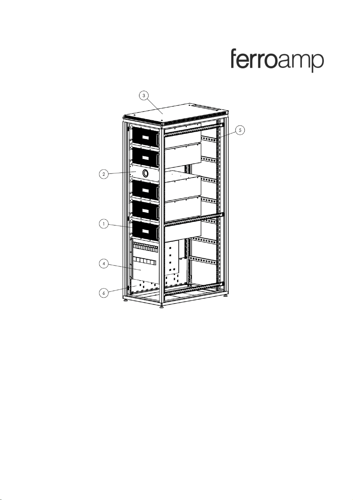
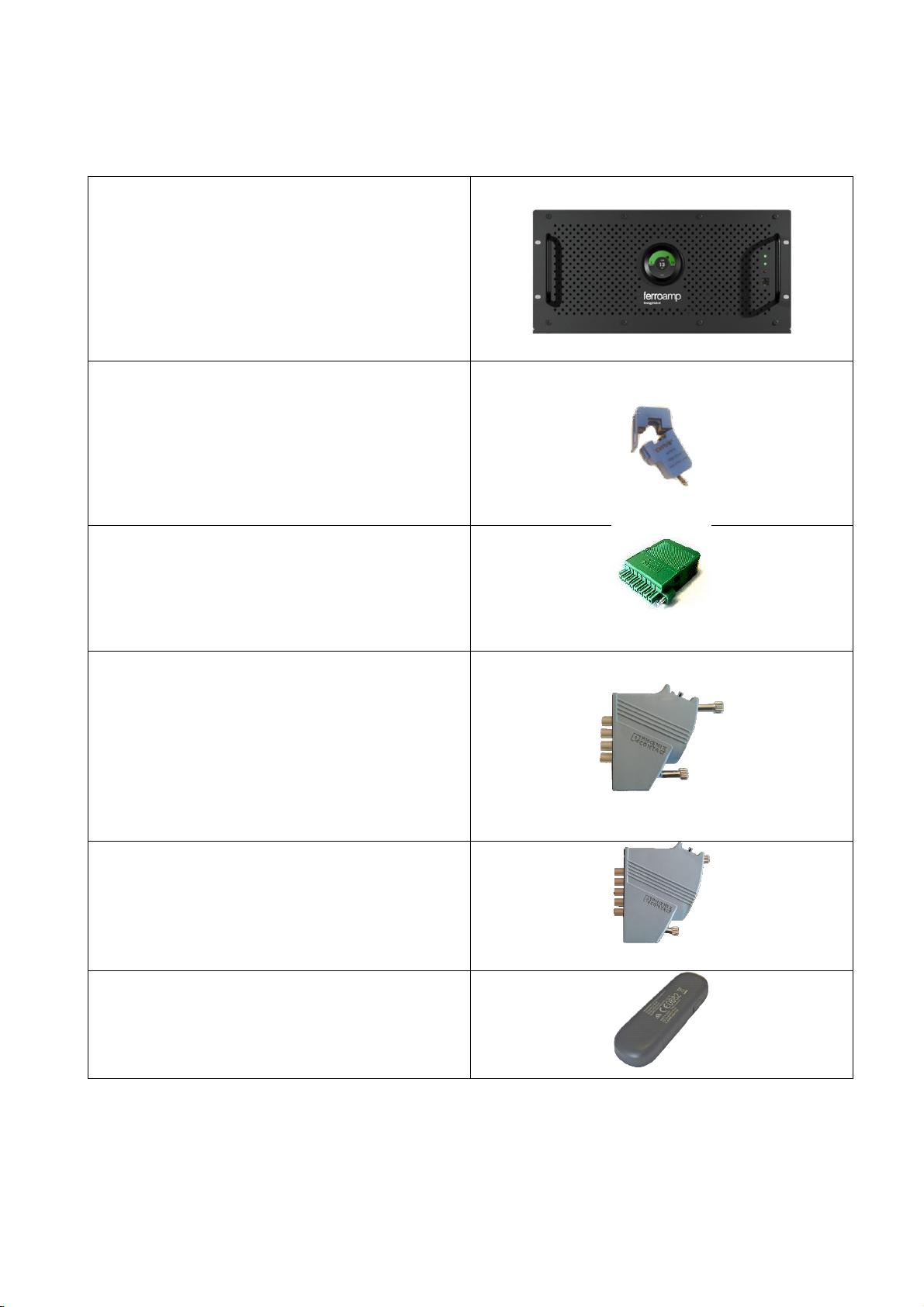
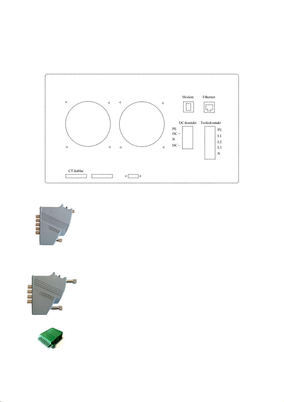
1.Articles
EnergyHub XL 28 kW
3 Current transformers with 10m connecting
cable. Specify size before order.
Contact for current transformers.
Connector for connection to DC grid.
Three phase contact for AC grid connection
3G modem for internet connection (optional)
2
1Placement of cabinet
•Measures of Cabinet 42 U: Width: 600mm, depth:
1000mm and height: 2100mm.
•Measures of Cabinet 24 U: Width: 600mm, depth:
1000mm and height: 1300mm.
•Leave 5 cm at the back of the cabinet to ensure free
airflow.
•EnergyHub XL is pushed from the front into the cabinet
and it is therefore recommended to have at least 1
meter of free space up front to facilitate installation.
•Make sure to have access to at least one of the sides
or the back of the cabinet during installation to facilitate
contacting
•The side walls of the cabinet are removable.
•Temperature: -25 –55
•Relative humidity: 0-95%
•The room where the inverter is placed should be well ventilated. The heat development
can be up to 2% of the maximum effect. A fully fitted cabinet with 5x28 kW can generate
2.8 kW of heat at 2% loss.
3
2Installation of current transformers
To be able to utilize power equalization and the analysis tools that are available, current
transformers need to be installed and connected to the Energyhub. These measurements
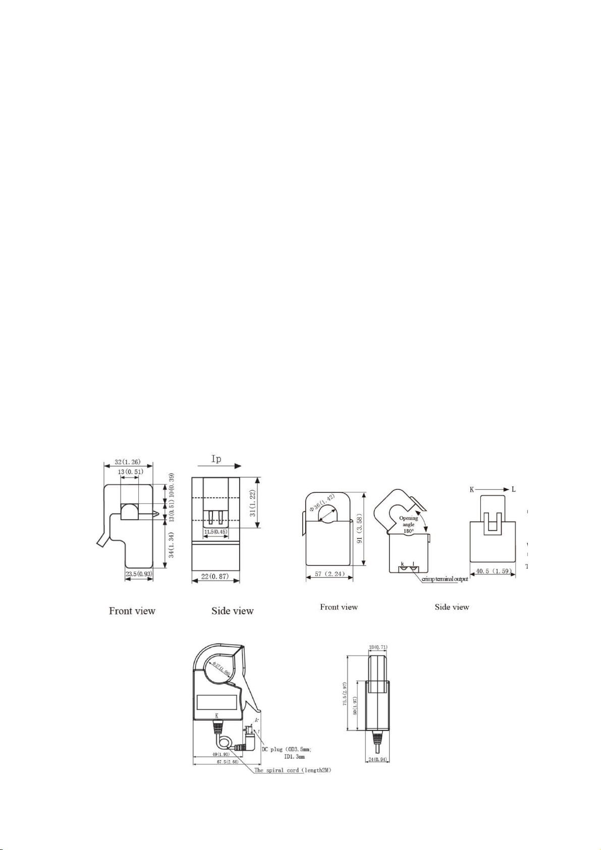
form the basis for several of the functions in the system. There are three different types
of current transformers available. The choice of transformer depends on the current in
the cables and its diameter.
< 100A, ratio 2000
The smallest current transformers can manage up to 100 A per phase conductor and a
maximum diameter of 13mm. The conversion rate is 2000.
< 160A, ratio 4000
The second largest current transformers can manage up to 160 A per phase conductor
and a maximum diameter of 27mm. The conversion rate is 4000.
< 600A, ratio 6000
The largest current transformers can manage up to 600 A per phase conductor and a
maximum diameter of 36mm. The conversion rate is 6000.

4
Installation of current transformers
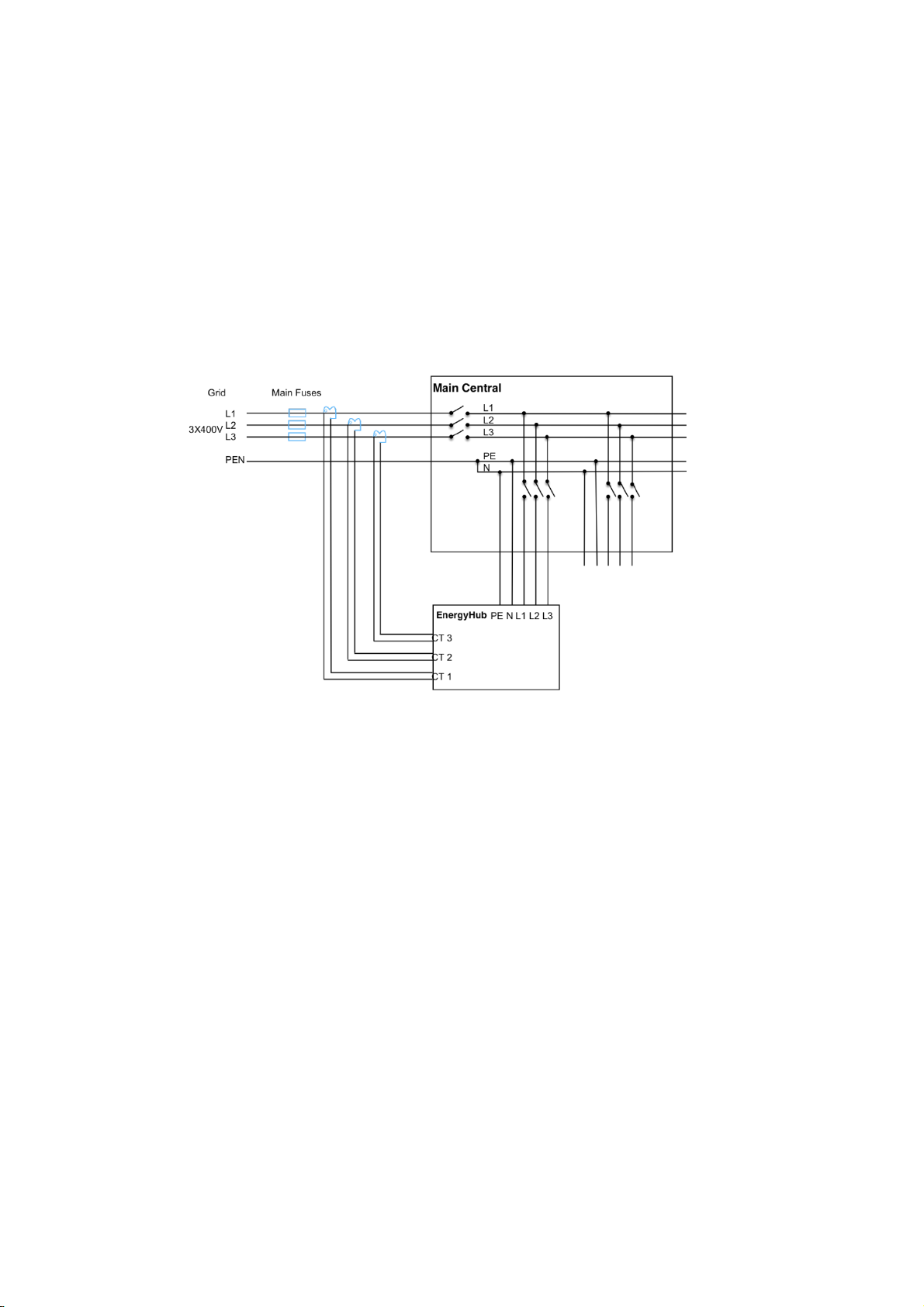
•Install the current transformers on all three phase conductors. Current transformers should
be installed between incoming power and EnergyHub. See diagram under section 5.
•Make sure that all current transformers have been closed properly. If they are open,
calibration will fail.
•EnergyHub contains an automatic calibration function which ensures the function of each
transformer regarding phase order and current direction. The calibration ensures correct
functionality for current equalization and measurements.
•Adjust the cable length and connect them to the connector as shown in the picture
below. Note the order of the phase conductor.
Control of current transformers:
•Notes: It is important that the current transformers are completely sealed around the
cable. If they are not closed properly, the measurements may be incorrect.
•To ensure correct connection, check the resistance between the pairs: white-red, blue-
black and green-yellow. All pairs should have approximately the same resistance. If any
of the pairs deviate or do not have contact, there may be a failure with the connection.
Make sure that the connector and all current transformers are closed.
5
Connection of EnergyHub XL.
Every inverter is installed from the front of the cabinet and is attached to the sides with
M6 screws.
Connect the cables in the cabinet to the EnergyHub XL as follows:
•Five-pole AC-contact.
•Four-pole DC-contact.
•Green CT-contact.
6
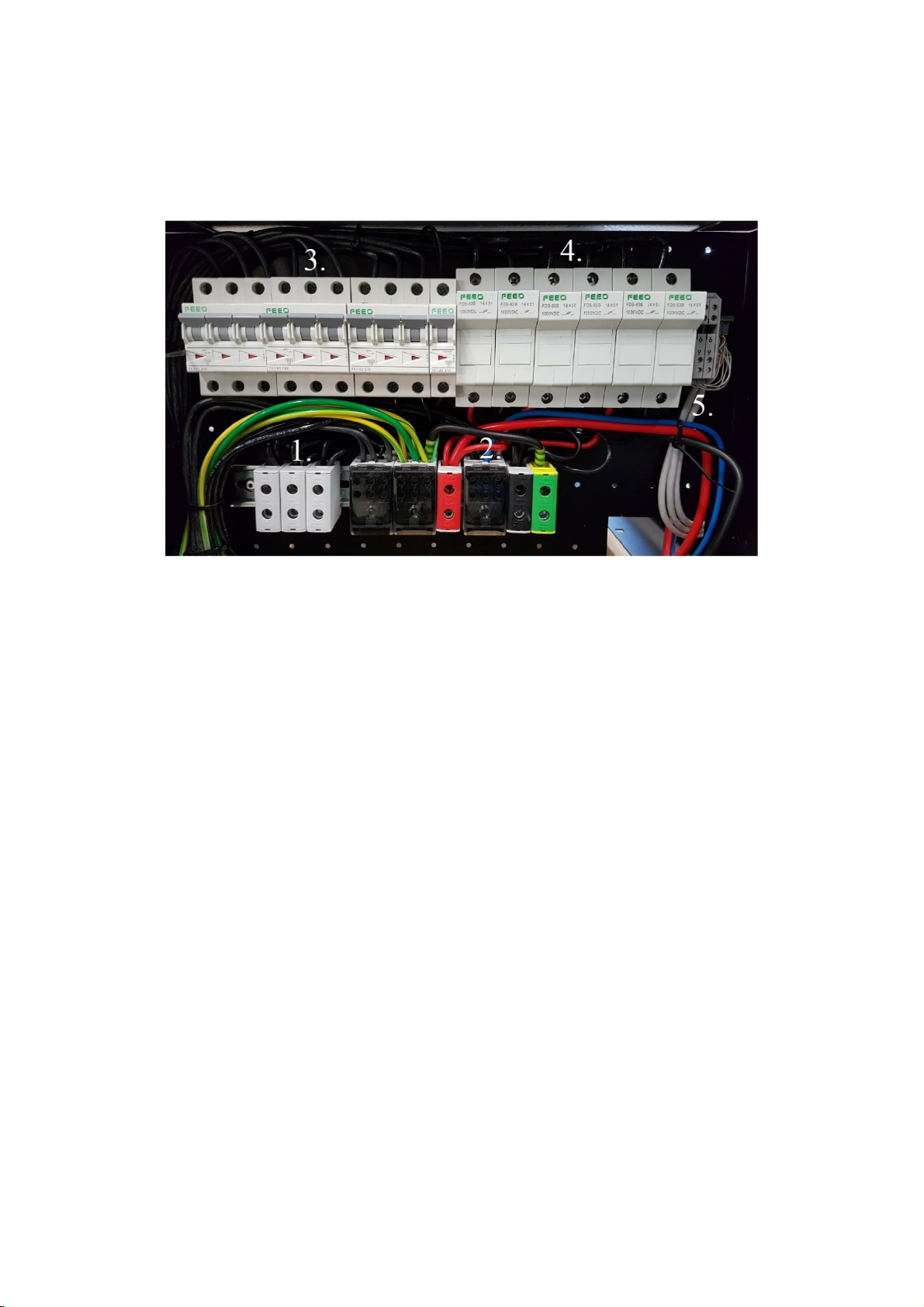
3Connection cabinet
•Connect the three-phase cable to the marked terminals in the cabinet.
•There are built-in circuit breakers in the cabinet to every EnergyHub XL.
•The current in the neutral conductor to the EnergyHub can get up to 1.7 times larger
than the rated current at full current equalization.
•It is recommended to install a circuit breaker for the whole cabinet.
7
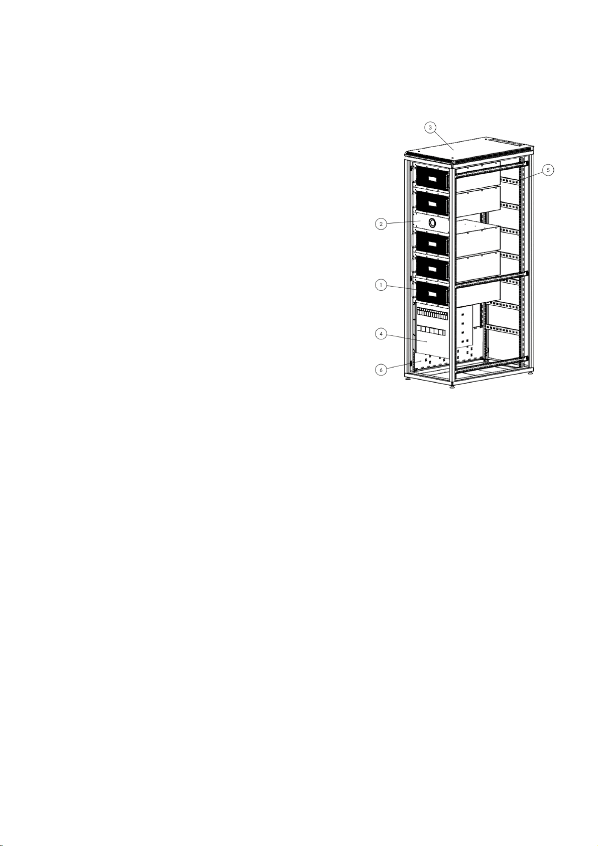
The picture below shows the different connectors in the distribution designed for three
EnergyHub XL. The number may vary depending on how many inverters are connected
to the cabinet.
1Terminals for AC connection
2Terminals for DC connection
3Breaker and fuses for AC
4Fuses for DC to each EnergyHub Xl
5Terminals for current transformers

8
4Internet Connection
The System needs access to internet in order to present measurements and data to the
portal as wells as software updates.
9
5Commissioning
•Start the EnergyHub by closing the breaker
•Wait for one minute for the display starts.
•Press and hold on the display until it says Service menu activated
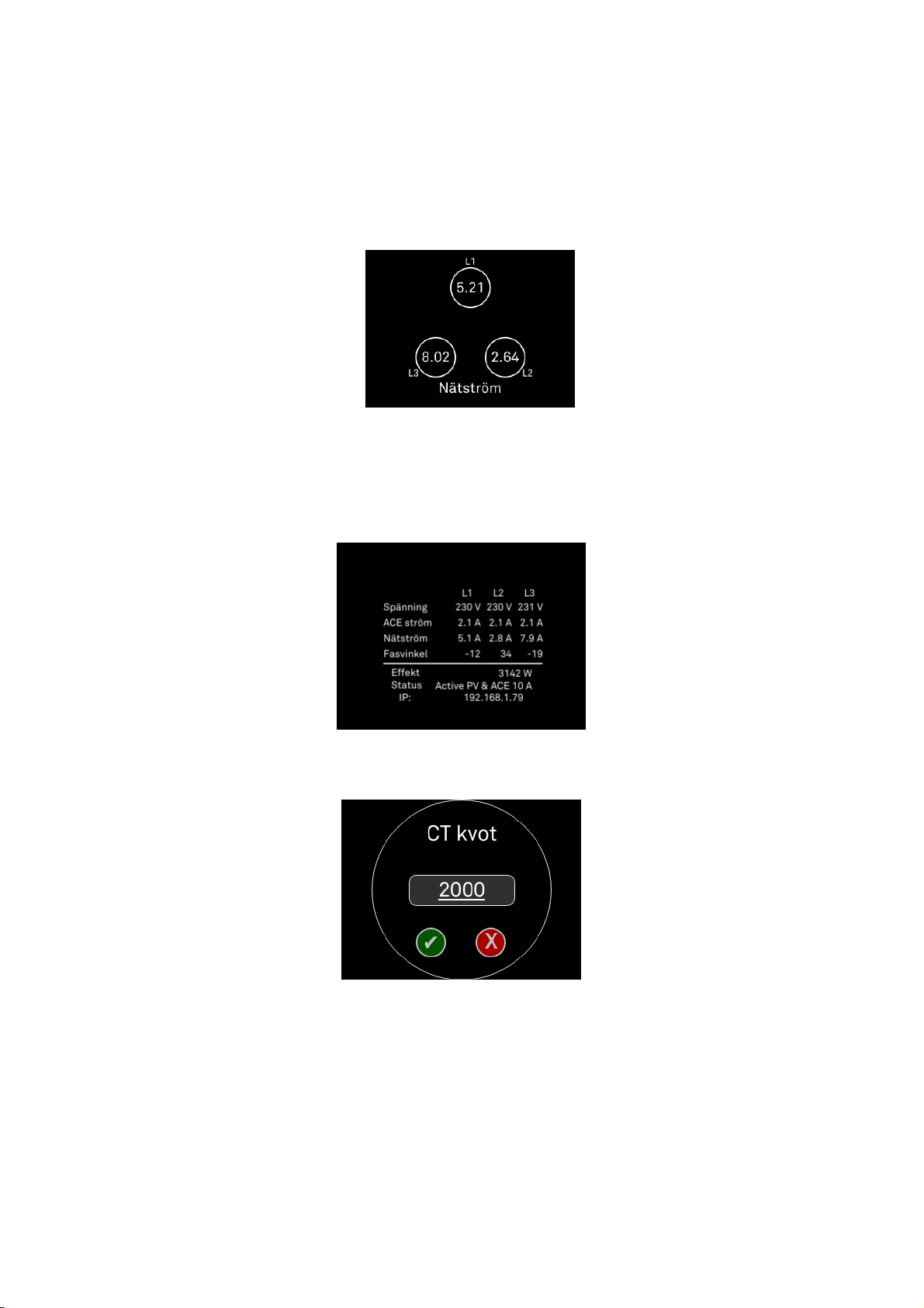
•Sweep right and left to switch between different views.
•Sweep until you find the Table view, seen below, and verify that the system is inactive.
If not sweep to the Start and Stop menu and press Stop.
•Go the CT-ration view and insert the correct CT-ratio
•To change the CT ratio push on the number.
10
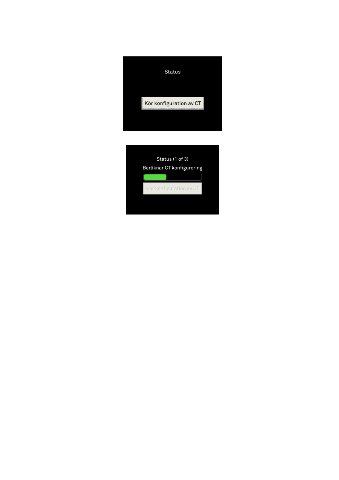
•To start the calibration, sweep to the view “Run CT calibration” and push
•The configuration might take up to 5 minutes, during this time a progress bar is displayed
•If the configuration fails, check that the current transformers are correctly installed.
•Om displayen visar ”Konfigureringen misslyckades” är strömtängerna in rätt inkopplade.
•Note; in order to have a fully functional system the CT configuration must pass.
11
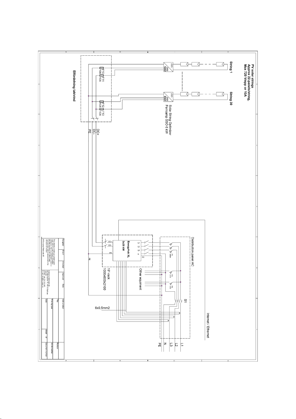
6Single line diagram
12
User manual
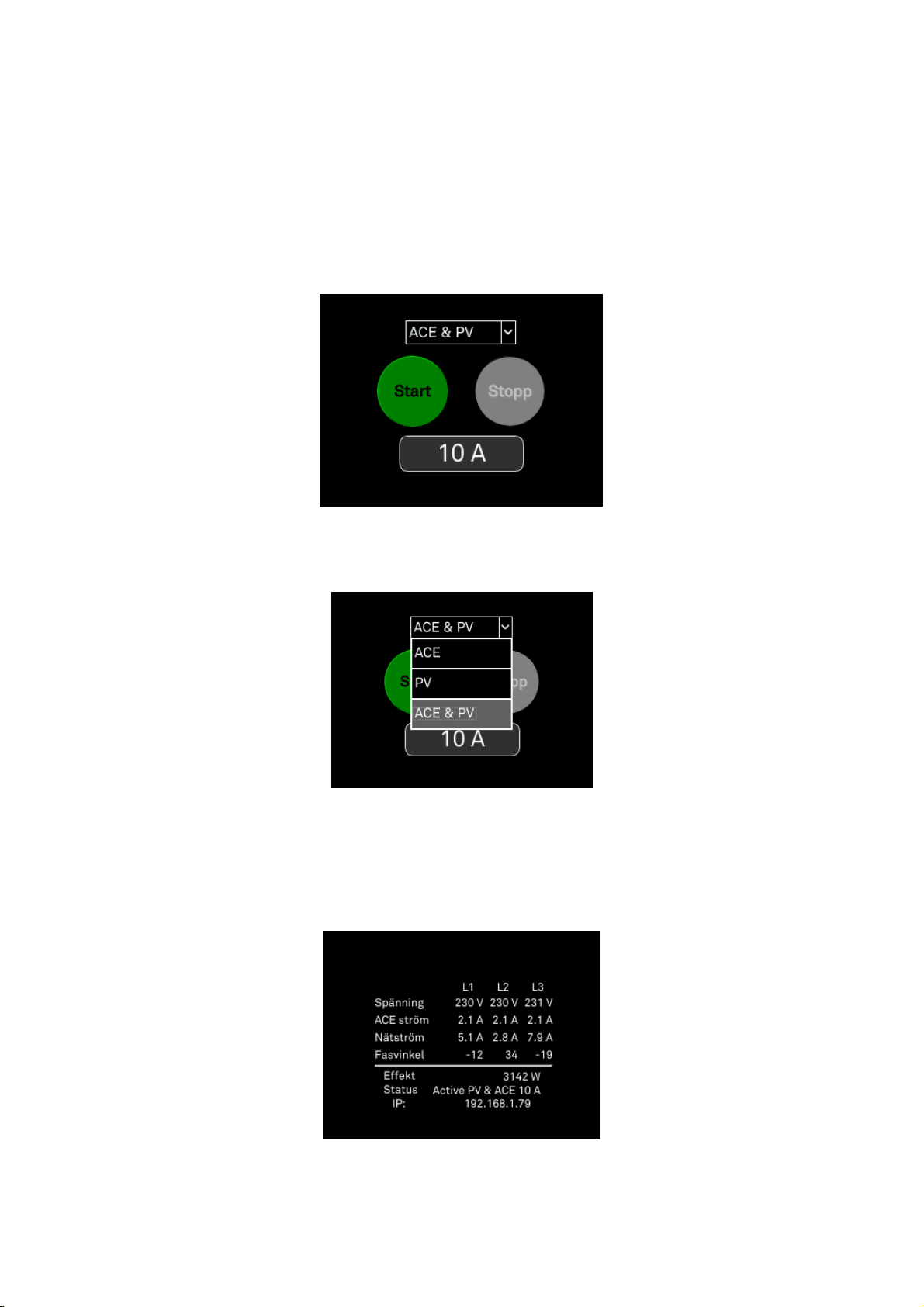
1.Activate ACE and solar production
•Press and hold the display until “Service menu enabled”is shown.
•Choose ACE & PV from the drop-down menu.
•Press the number at the bottom in order to change the threshold for the current
equalization.
•Press start
•Verify that the system is running the correct settings in the table view
13
2.Change ACE limit
•Press and hold the display until “Service menu activated” is shown.
•Press Stop.
•Press the number at the bottom in order to change the threshold for the current
equalization.
•Press Start.
•Verify the status in the table view
•Press and hold the display to go back to operational mode.
14
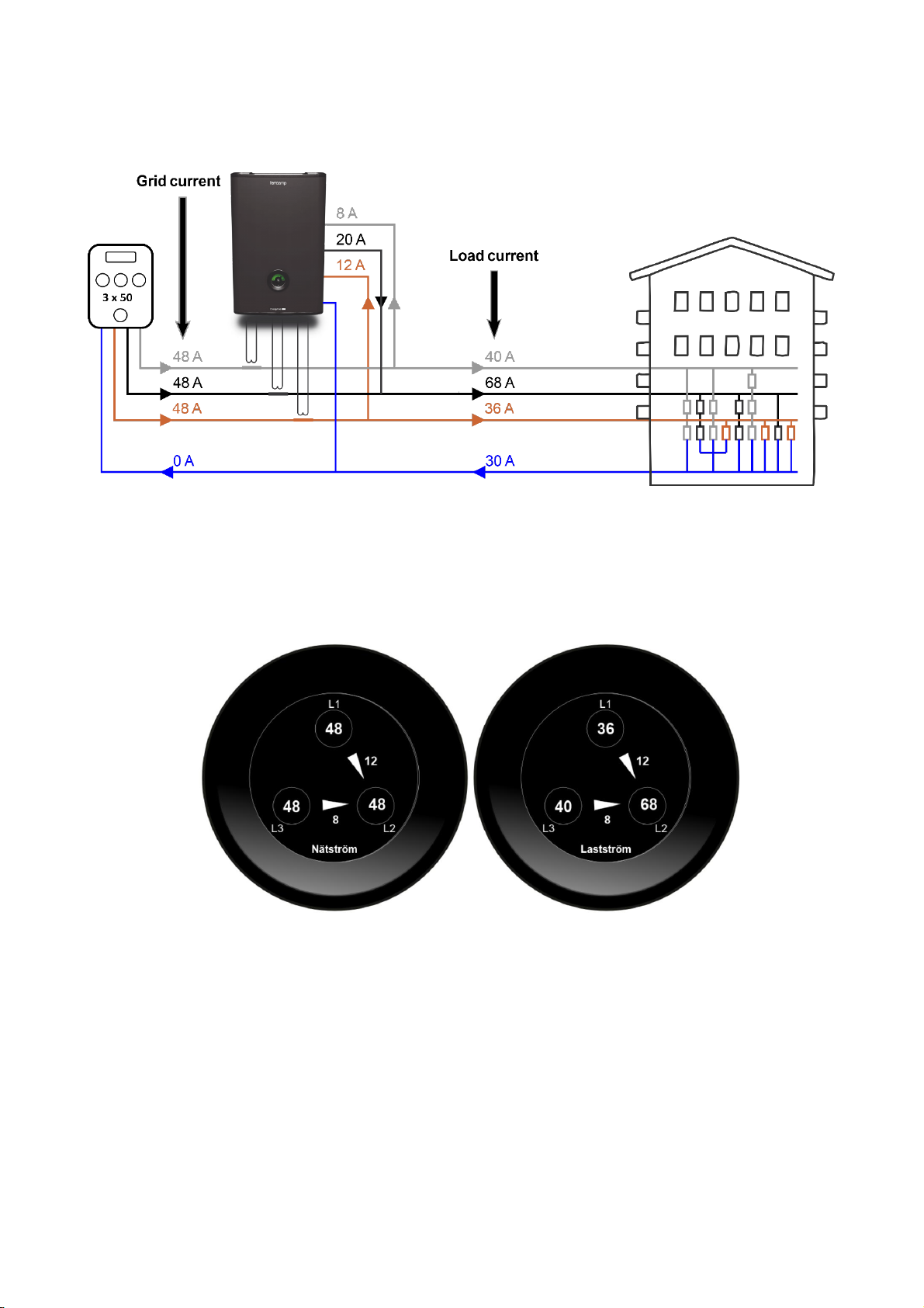
3.Grid current and Load current
•Grid current shows the current over the main fuse
•Load current shows the current inside the facility
•When ACE is activated, the transferred currents is shown by the arrows between
the phases.

15
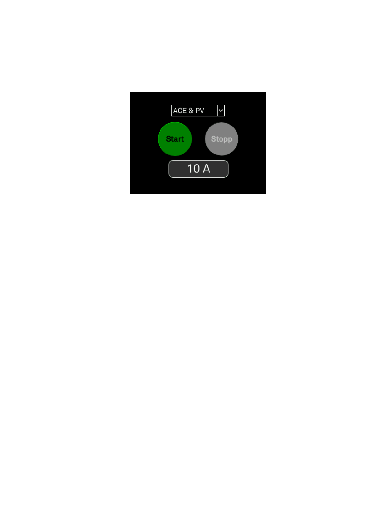
4.Activate ACE only
•Press and hold until “Service menu enabled”is shown.
•Swipe to the ”Start and Stop” display.
•Choose “ACE only” in the drop-down menu
•Choose the current limit that triggers the ACE function
•Press Start
•Verify the status at the table view
•Press and hold the display to go back to operational mode.

16
5.Activate Solar production
•Press and hold until “Service menu enabled” is shown.
•Swipe to the ”start and stop” display.
•Choose “PV only” in the drop-down menu
•Press Start
•Verify the status at the table view
•Press and hold the display to go back to operational mode.
Other manuals for EnergyHub XL
1
Table of contents
Popular Network Accessories manuals by other brands

Panduit
Panduit Z11C Series installation instructions

Auerswald
Auerswald COMtrexx Business instructions

Paradyne
Paradyne Hotwire 8620 reference guide

Dell
Dell EMC Edge 510 LTE installation guide

Paradyne
Paradyne COMSPHERE 6800 Series Command reference manual

Inline
Inline COURT DIRECTOR CD100 Operation manual


