ferrotec CARRERA User manual
Operation manual
High-voltage power supply unit
Type: CARRERA
Serial no:
FERROTEC GmbH
Postfach 33
Seerosenstraße 1
72669 Unterensingen
Telefon: +49 7022 - 9270-0
Telefax: +49 7022 - 9270-10
Internet: www.ferrotec-europe.com
E-Mail: ebgun@de.ferrotec.com Version 1.3_15
Translation of the original Operation manual

Electron Beam Evaporator
Types: EV M –6; EV M –8; EV M –10
Rev 1.3_15
1
NOTICE
This instruction handbook is an integral part of the high voltage
power supply and must be kept readily at hand for the operating
personnel at all times.
The safety instructions contained in it must be obeyed.
If the machine is resold, the instruction handbook must always be
delivered with it as well.
Liability
The manufacturer's liability for the CARRERA power supply is
based on the principles of German law.
The manufacturer accepts no liability for damage and losses due
to:
improper use;
operation by unauthorised personnel;
failure to follow safety regulations;
failure to heed the information in the instruction handbook.
Translation
If the machine is sold to a country in the EEA, this instruction
handbook must be translated into the language of the country in
which the machine is to be used.
Should the translated text be unclear, the original instruction
handbook (German) must be consulted or the manufacturer
contacted for clarification.
Copyright
No part of this publication may be reproduced, transmitted, sold or
disclosed without prior permission. Damages will be claimed for
violations.
All rights reserved.

Version 1.3_15 EN
2
High Voltage Power Supply
Type: CARRERA
1 Table of Content
1.1 Table of content
1Table of Content 2
1.1 Table of content 2
1.2 Table of pictures 4
1.3 Manufacturer's Declaration 5
2Overview and Intended Use 6
2.1 Overview CARRERA-System 6
2.2 Intended Use 7
2.3 Explanation of terms 8
2.4 Technical specifications 9
2.4.1 Dimensions and weight 9
2.4.2 Specification 9
2.4.3 General specifications 9
3Safety 10
3.1 Notes / Explanations 10
3.1.1 Explanation of used safety symbols 11
3.1.2 Machine Identification 12
3.2 Integrated Safety Systems 13
3.3 Overview of electrical connections 16
3.4 Safety Precautions (by the Operator) 17
3.5 Responsibilities of the Operator 19
3.6 Safety Inspections and Tests 22
4General Warnings 23
4.1 Dangers 23
4.2 Operating Areas and Danger Zones at the
Machines 24
4.3 Operating and Maintenance Personnel 25
4.4 Spare and Wearing parts 26
4.5 Shutdown Procedure 27
5Installation 28
5.1 Delivery package 28
5.2 Transport and Packaging 29
5.2.1 Delivery (also for Spare and replacement
Parts) 29
5.3 Intermediate Storage 30

Version 1.3_15 EN
3
High Voltage Power Supply
Type: CARRERA
5.4 Transportation to the point of Installation
( by Operator) 30
5.5 Assembly, Installation (only for trained
personnel) 31
5.5.1 Assembly 31
5.5.2 Electric Connection 31
5.5.3 Overview of the electrical connectors and
fuses 34
5.5.4 Connection of the high-voltage power supply
unit 35
6Functional description 39
6.1 Putting in operation for the first time (for
specialized personnel only) 41
7Operation 43
7.1 Operation and displaying elements 43
7.2 Operation modes 44
7.2.1 Operation 44
7.2.2 Switching on 44
7.2.3 Switching off 45
8Cleaning/Maintenance 46
8.1 Complete Daily Cleaning 48
8.2 Cleaning 48
8.3 Maintenance 48
8.3.1 Function test plan 49
8.3.2 Inspections 49
8.4 Inspection of the machine 51
9Troubleshooting 52
10 Emergency 53
11 Dismantling/Disposal 54
12 Appendix; Options 55
12.1 Appendix 1; Control unit GENIUS 55
12.2 Appendix 2; Filament Power Supply FPS 56

Version 1.3_15 EN
4
High Voltage Power Supply
Type: CARRERA
1.2 Table of pictures
Fig. 1 Overview CARRERA system 6
Fig. 2 Electrical connections of the high voltage
power supply ( front side) 16
Fig. 3 Electrical connections of the high voltage
power supply ( back side) 16
Fig. 4 Delivery package 28
Fig. 5 Wiring diagram of the CARRERA 3/5/6 high
voltage power supply 33
Fig. 6 Wiring diagram of the CARRERA 10/12 high
voltage power supply 33
Fig. 7 Overview of electrical connectors and fuses 34
Fig. 8 Interlock connector 37
Fig. 9 Harting plug, connector assignment of the
power supply cable 38
Fig. 10 Overview high voltage power supply 39
Fig. 11 Overview of operation and display elements 43
Version 1.3_15 EN
5
High Voltage Power Supply
Type: CARRERA
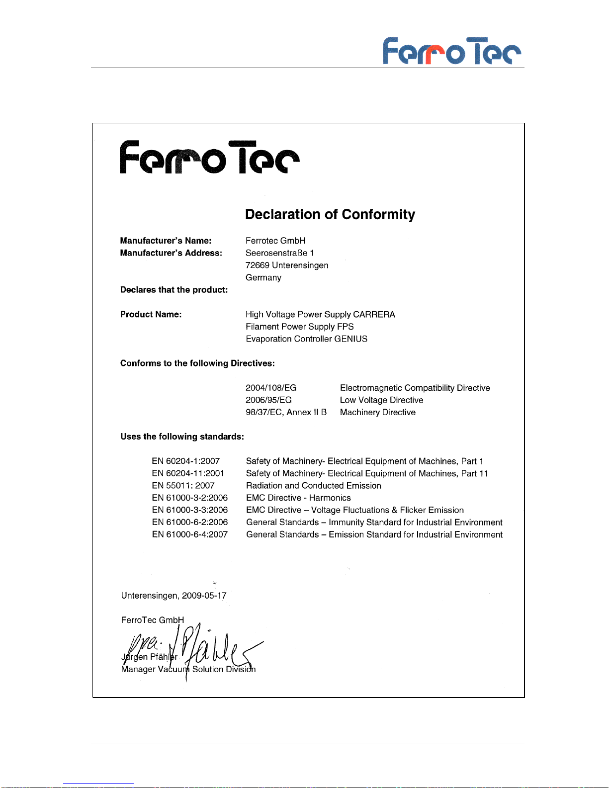
1.3 Manufacturer's Declaration
Version 1.3_15 EN
6
High Voltage Power Supply
Type: CARRERA
2 Overview and Intended Use
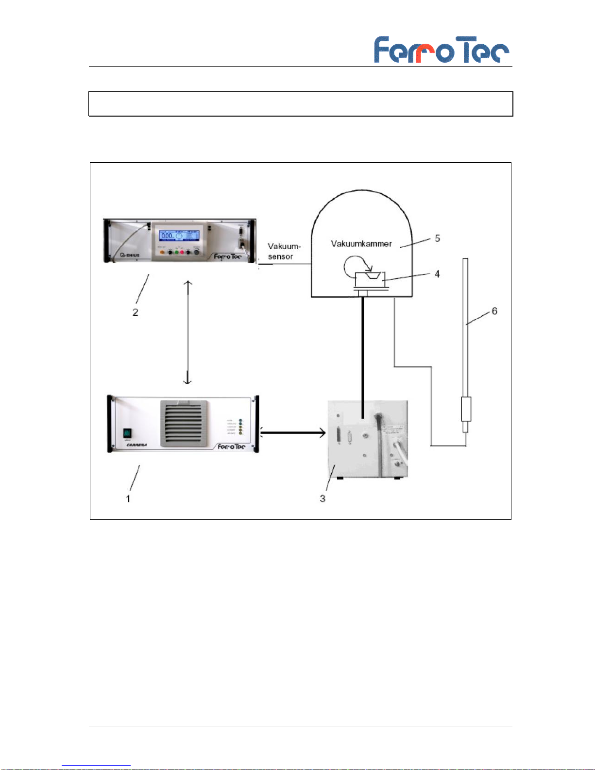
2.1 Overview CARRERA-System
Fig. 1 Overview CARRERA system
The complete evaporator package consist of the following:
1 High voltage power supply HVP
2 Electron beam evaporator controler GENIUS with hand
remote control
3 Filament power supply (FPS)
4 Electron beam evaporator
5 Vacuum chamber
6 Grounding rod
Version 1.3_15 EN
7
High Voltage Power Supply
Type: CARRERA
2.2 Intended Use
The high voltage power supply HVP is part of a group of devices
for the operation of an electron beam evaporator installed in a
vacuum chamber..
The group of devices consists of:
- High voltage power supply (HVP)
- Electron beam evaporator controller GENIUS with integrated
remote control
- Filament power supply (FPS)
- Grounding rod
Use of the high voltage power supply for any other purpose
requires the approval of the manufacturer.
The high voltage power supply HVP generates the high voltage
needed to operate an electron beam evaporator. Other fields of
application are only permitted with the written authorization of the
manufacturer.
This operating manual deals solely with the design and operation
of the high voltage power supply. Please see the relevant
operating manuals for operation of the other devices in the group
(see table of contents and figures, appendices 1 + 2).
These devices were developed, designed and built solely for
commercial/industrial use.
DANGER
The high voltage power supply HVP is intended solely for the
purpose described above. Any other use or modification of the
high voltage power supply HVP without the written consent of
the manufacturer is deemed improper. The manufacturer
accepts no liability for resultant damage. The risk is borne
solely by the operator.
The high voltage power supply HVP may only be put into
operation when it has been ensured that all safety equipment is
operative and the total installation of the vacuum system
comply with EU directives.

Version 1.3_15 EN
8
High Voltage Power Supply
Type: CARRERA
Proper use of the machine in accordance with its intended use
includes compliance with the manufacturer's operating,
maintenance and repair instructions. The use is restricted to
rooms in a building or halls.
HINWEIS
Notice on application of the EMC Directive 2004/108/EC in the
manufacturer's declaration:
The high voltage power supply HVP is only allowed to be
operated in Industrial environment.
2.3 Explanation of terms
HVP - High voltage power supply unit
GENIUS - Electron beam evaporation controller
FPS - Filament Power Supply

Version 1.3_15 EN
9
High Voltage Power Supply
Type: CARRERA
2.4 Technical specifications
2.4.1 Dimensions and weight
Width: 483 mm
Height ( 3, 5 und 6 kW units): 175 mm
Height (10 und 12 kW units): 350 mm
Depth: 550 mm
Weight: approx. 28,5 kg kg
2.4.2 Specification
Power:
3 kW
5 kW
6 kW
10 kW
12 kW
Mains power supply:
EU Version:
3 x 400V
+/-10 %
US Version:
3 x 208V
+/-10 %
EU Version:
3 x 400V
+/-10 %
US Version:
3 x 208V
+/-10 %
EU Version:
3 x 400V
+/-10 %
US Version:
3 x 208V
+/-10 %
EU Version:
2X 3 x 400V
+/-10 %
US Version:
2X 3 x 208V
+/-10 %
EU Version:
2X3 x 400V
+/-10 %
US Version:
2X3 x 208V
+/-10 %
Frequency:
50/60 Hz
50/60 Hz
50/60 Hz
50/60 Hz
50/60 Hz
Control Volage:
4 - 10 kV
4 - 10 kV
4 - 10 kV
4 - 10 kV
4 - 10 kV
High voltage set point:
4 bis 10 V,
DC (entspr.
4 - 10 kV)
4 bis 10 V,
DC (entspr.
4 - 10 kV)
4 bis 10 V,
DC (entspr.
4 - 10 kV)
4 bis 10 V,
DC (entspr.
4 - 10 kV)
4 bis 10 V,
DC (entspr.
4 - 10 kV)
Emission current:
0 -300 mA
0 - 500 mA
0 - 600 mA
1.000 mA
1.200 mA
Emission current actual
valuet:
0 -10 V, DC
(0 -300 mA)
(0 - 500 mA)
(0 - 600 mA)
(0–1000 mA)
(0–1.200 mA)
Electrical connection:
(see chap.5.5.2)
EU Version :
3 x 16 A
slow blow
US Version:
3 x 25 A
slow blow
EU Version :
3 x 16 A
slow blow
US Version:
3 x 25 A
slow blow
EU Version :
3 x 16 A
slow blow
US Version:
3 x 25 A
slow blow
EU Version :
2X3 x 16 A
slow blow
US Version:
2X3 x 25 A
slow blow
EU Version :
2X3 x 16 A
slow blow
US Version:
2X3 x 25 A
slow blow
2.4.3 General specifications
Ambient temperature :
Lower limit: -10 bis 35 °C
Upper limit : + 40° C
Air humidity max: 65 %
Noise level: LPA = < 70 dB (A)
Version 1.3_15 EN
10
High Voltage Power Supply
Type: CARRERA
3 Safety
3.1 Notes / Explanations
DANGER
“DANGER” warns of dangerous situations. Avoid these
dangerous situations! Otherwise they could result in severe
injury or death.
WARNING
“WARNING” warns of dangerous situations. Avoid these
dangerous situations! Otherwise they could result in severe
injury or death.
CAUTION
“CAUTION” in connection with this warning symbol warns of
dangerous situations. Avoid these dangerous situations!
Otherwise they could result in severe injury or death.
NOTICE
“NOTICE” gives you recommendations for action, and there is
no risk of injury if you fail to comply with them. However, follow
these recommendations for action to avoid damage and
annoyance.
NOTICE
Instruction manual mandatory;
framed and marked with a book symbol.
NOTICE
„NOTICE“are marked with the word "NOTICE" . This informs
you about further literature.
Version 1.3_15 EN
11
High Voltage Power Supply
Type: CARRERA
3.1.1 Explanation of used safety symbols
DANGER
Danger from electric current
framed and marked with the symbol shown opposite.
DANGER
Danger of burns
framed and marked with the symbol shown opposite.
DANGER
Danger of your hands being crushed or injured
framed and marked with the symbol shown opposite.
DANGER
Danger from magnetism
framed and marked with the symbol shown opposite.
DANGER
Danger for people with cardiac pacemakers (and with insulin
pumps and people with active or passive prostheses and
ferromagnetic or conductive foreign bodies) are marked with
the symbol shown opposite.
NOTICE
Protective conductor connection
marked at the connection points by the symbol shown opposite.
NOTICE
Environment sign
marks actions to protect the environment.

Version 1.3_15 EN
12
High Voltage Power Supply
Type: CARRERA
3.1.2 Machine Identification
Seriel-Nummber
The information in this instruction handbook only applies to the
High voltrage power supply whose type designations are given
on the title page
The identification plate including the serial number is attached on
the back of the high voltage power supply.
It is important that the type designation and the serial number is
stated correctly when consulting us.
We can only process your query properly and quickly if this
information is correct.
Version 1.3_15 EN
13
High Voltage Power Supply
Type: CARRERA
3.2 Integrated Safety Systems
The integrated safety systems must be checked at regular
intervals (d= daily, w = weekly, m = monthly, ½ y = half-yearly,
y= yearly).
The test methods that are to be applied are:
V= visual inspection, F= function test, M= measurement.
The operator must implement the following in the overall
plant:
Mains Isolator (Main Switch)
The high voltage power supply is
connected to the main power supply
system. The electron beam evaporator
is connected to and disconnected from
the power supply with the main switch
for this power supply system.
DANGER
When the main switch is switched off for cleaning, maintenance
and repair work, it must be locked with a padlock to prevent
unauthorised switching on.
Emergency Stop System
The high voltage power supply has to
be integrated in a master emergency
stop system that immediately puts the
high voltage power supply into a safe
operating state when actuated.
Safety System
Discharge rod,
Safety switch at the vacuum
chamber for the evaporator,
Safety latch for interlocks
Flow controller
Vacuum monitor,
Test
Interval
Method
m
F
Test
Interval
Method
m
F
Test
Interval
Method
y
F
Version 1.3_15 EN
14
High Voltage Power Supply
Type: CARRERA
Stop valve for the cooling water
supply.
Internal Interlock circuit
Using the plug X304 the CARRERA
high voltage power supply hast o be
integrated into the emergency shut off
circuit of the complete vacuum system
Machine Control System
The machine control system has to be
equipped internally with a three-phase,
five-wire supply system with current-
carrying mid-point conductor and
separate ground conductor (with
YELLOW/GREEN insulation).
DANGER
The owner is required to ensure that the unauthorized persons
( i.e., who are not operating or maintenance personnel) are
prevented from entering the operating area.
The operating and maintenance personnel are trained in the use
of the machine at its point of installation by personnel from
FERROTEC GmbH. Should you have any questions or be
uncertain about anything, please contact FERROTEC GmbH.
.
NOTICE
It is strictly forbidden to render any of the safety systems
inoperative or to modify their action.
NOTICE
This instruction handbook is an integral part of the electron
beam evaporator and must be kept readily at hand for the
operating personnel at all times. The safety instructions
contained in it must be obeyed.. If the electron beam
evaporator is resold, the instruction handbook must always be
delivered with it as well.
Test
Interval
Method
m
F
Test
Interval
Method
y
V, F, M

Version 1.3_15 EN
15
High Voltage Power Supply
Type: CARRERA
NOTICE
The type, scope and action of the safety systems were
arranged with the operator.
Version 1.3_15 EN
16
High Voltage Power Supply
Type: CARRERA
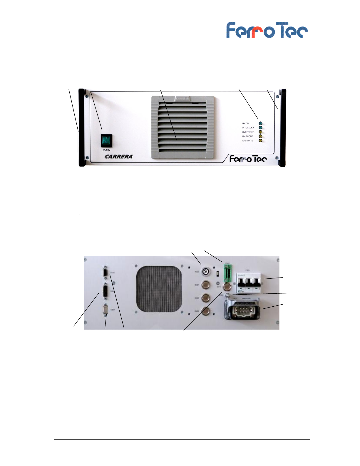
3.3 Overview of electrical connections
Fig. 2 Electrical connections of the high voltage power supply ( front side)
Front side of the high voltage power supply:
1 Transportation handle
2 ON/OFF switch
3 Air filter inlet
4 LED-Display
13
Fig. 3 Electrical connections of the high voltage power supply ( back side)
Back side of the high voltage power supply:
5 High voltage output
6 Interlock connection
7 Digital interface (connection to Control unit)
8 Analoginterface (connection to Control unit)
9 Fuses
10 Grounding
1 2 3 4 1
5 6
7 12 8
9
10
11

Version 1.3_15 EN
17
High Voltage Power Supply
Type: CARRERA
11 Mains supply
12 Connection Master/Slave: Control signal
13 Connection Master/Slave: Interlock signal
3.4 Safety Precautions
(by the Operator)
The operator must:
- instruct his operating and maintenance personnel in the use
of the safeguards of the electron beam evaporator and
- ensure the safety precautions are being observed including
the use of personal protective equipment.
- The owner must ensure that entry to the hazard area of the
machine (into which the high voltage power supply has been
built) by unauthorized persons (no operating and
maintenance personnel) is prevented. The minimum
clearances stated in DIN EN ISO 13857 are to be complied
with when installing the high voltage power supply.
- The high voltage power supply may only be operated when
the safety devices of the machine into which the high voltage
power supply has been built have been activated. The person
setting up the entire machine must ensure that through
suitable technical measures.
- The cutting off of the energy sources is to be done in such a
way technically that the switching-off procedure described
under section 4.5 can be complied with.
This instruction handbook must be kept in a safe place for future
reference. The frequency of inspections and checks must be
observed.
The work described in this instruction handbook is explained in
such a way that
-the chapters on operation and modes of operation can be
understood by an instructed person and
-those on transport, installation and assembly, maintenance
and troubleshooting by a skilled person.
The chapters on transport, installation and assembly,
maintenance and troubleshooting are intended for skilled
persons only. Work described in these chapters may only be
carried out by such skilled persons.

Version 1.3_15 EN
18
High Voltage Power Supply
Type: CARRERA
Instructed Person
A person familiarised with and, if applicable, trained in his or her
particular duties by a skilled person and advised of the risks of
improper conduct and about the necessary safeguards and
safety precautions.
Skilled Person
A person with relevant technical training, know-how, experience
and knowledge of applicable standards to enable him or her to
assess the work assigned to him or her and to perceive potential
risks.
Definitions based on EN 60204-1:2006
Version 1.3_15 EN
19
High Voltage Power Supply
Type: CARRERA
3.5 Responsibilities of the Operator
NOTICE
In the EEA (European Economic Area) national implementation
of the framework directive 89/391/EEC and corresponding
individual directives, in particular the directive 2009/104/EEC
concerning the minimum safety and health requirements for the
use of work equipment by workers at work, as amended, are to
be observed and adhered to. In Germany the Plant Safety
Ordinance of October 2002 must be observed (translation of
the above-mentioned directive into national law).
The operator must (where necessary) obtain any local operating
permits required and observe the provisions contained therein
In addition to this he must observe local laws and regulations on
- personnel safety (accident prevention regulations)
- safety of work materials and tools (safety equipment and
maintenance)
- disposal of products (laws on wastes)
- disposal of materials (laws on wastes)
- cleaning (cleaning agents and disposal)
- environmental protection.
In addition, the owner must note:
A constant hazard evaluation of the workplaces (danger of
hands being crushed, danger of stumbling) is to be carried
out. The measures are to be defined in work instructions and
the working personnel are to be instructed accordingly
The supervisors must check compliance with the measures
stated in the work instructions.
Ensure that the operating personnel are suitably trained.
Work on electrical equipment is only to be carried out by
suitably trained persons. The connecting cables and
terminals must be properly insulated and covered.
It is only possible to ensure optimal functioning of the
elements if the machine controller is working perfectly. The
switching states of the limit switches must be properly
incorporated into the machine controller and the signal cables
must be in perfect condition.
Table of contents
Other ferrotec Power Supply manuals


