ferrotec Temescal CV-6SLX User manual

0101-8242-0
CV-6SLX USER MANUAL
Revision C, April 2016
Temescal, a division of Ferrotec (USA) Corporation
4569-C Las Positas Road, Livermore, CA 94551
Tel: 1-800-522-1215; Fax: 925-449-4096

Revision History
0101-8242-0
Rev. Change Description Reason/Application Date Appvd.
A First published version of CV-6SLX User
Manual, based on the CV-6SLX Technical
Manual, Rev. L.
Applies to all CV-6SLX units, with HV
power supplies with PNs 0620-1135-
0 (for 208-volt units) and 0620-1135-
1 (for 400-volt units)
March
2014 IA
B Corrections throughout to cross-references.
Minor changes to technical data in Section 5.
Deleted former section 5.6 (Suggested Spare
Parts lists).
Pursuant to Field Service review of
Rev. A Sept.
2015 IA
C Replaced all occurrences of 0620-9654-0 with
0620-9654-1 and all occurrences of 6024-
6112-1 with 0620-8684-1.
Pursuant to PN change ordered in
ECN 12185. April
2016 IA
© 2016 Ferrotec (USA) Corporation
TemEBeam is a trademark of Ferrotec Corporation.

0101-8242-0, Rev. C i CV-6SLX User Manual
Table of Contents
Page
Section Number and Title Number
1 Introduction to the CV-6SLX ........................................................................................1-1
1.1 Product Description.......................................................................................................1-1
1.2 CV-6SLX HVPS Description and Specifications .................................................................1-1
1.3 Filament Power Supply Description and Specifications .....................................................1-2
1.4 Miscellaneous Hardware and Interconnection Cables.......................................................1-3
1.5 TemEBeam EBC Integrated Controller ............................................................................1-3
2 Installation ...................................................................................................................2-1
2.1 Section Overview ..........................................................................................................2-1
2.2 List of Components and Cables Supplied with the Unit.....................................................2-2
2.3 Rack Mounting the Power Module (HVPS).......................................................................2-2
2.4 Mounting the Filament Power Supply Module(s)..............................................................2-3
2.5 Grounding Requirements...............................................................................................2-3
2.6 Cable Installation ..........................................................................................................2-7
3 Power Supply Operation ..............................................................................................3-1
3.1 Section Overview ..........................................................................................................3-1
3.2 HVPS Front Panel Controls and Indicators.......................................................................3-1
3.3 Switches and LEDs on the FPS Front Panel .....................................................................3-2
3.4 Power-Up Procedure......................................................................................................3-3
3.5 Control of Power Supply from TemEBeam EBC Integrated Controller................................3-3
3.6 Control of Power Supply by a PLC-Based System Controller .............................................3-8
3.7 Responding to Fault Conditions.................................................................................... 3-11
4 Theory of Operation .....................................................................................................4-1
4.1 Section Overview ..........................................................................................................4-1
4.2 Power Module Theory of Operation ................................................................................4-1
4.3 FPS Theory of Operation................................................................................................4-4
5 Troubleshooting ...........................................................................................................5-1
5.1 Section Overview ..........................................................................................................5-1
5.2 HVPS Front Panel LEDs..................................................................................................5-1
5.3 Ishikawa Diagrams........................................................................................................5-6
5.4 Troubleshooting Procedures......................................................................................... 5-15
5.5 FPS Fuse Replacement Procedure ................................................................................ 5-29
5.6 Suggested Spare Parts ................................................................................................ 5-31
Appendix A: Pinout Table for Power Module Diagnostic Port (HVPS J3) ..................................... A-1

CV-6SLX User Manual ii 0101-8242-0, Rev. C

0101-8242-0, Rev. C iii CV-6SLX User Manual
List of Illustrations
Figure Number and Title Page
Figure 1-1 CV-6SLX HVPS Front Panel......................................................................................................................... 1-1
Figure 1-2 Filament Power Supply Front Panel ............................................................................................................ 1-2
Figure 1-3 EBC Main Control Unit and Hand-Held Controller......................................................................................... 1-3
Figure 2-1 Mounting Hole Pattern for FPS Module(s).................................................................................................... 2-3
Figure 2-2 Facility Low Impedance Grounding Requirements........................................................................................ 2-4
Figure 2-3 System Low Impedance Grounding Requirements....................................................................................... 2-5
Figure 2-4 Rear Panel of CV-6SLX HVPS...................................................................................................................... 2-6
Figure 2-5 Grounding Studs on FPS Front Panel .......................................................................................................... 2-7
Figure 2-6 Input Power Connections to 208-Volt HVPS Units........................................................................................ 2-8
Figure 2-7 Input Power Connections to 400-Volt HVPS Units........................................................................................ 2-8
Figure 2-8 Input Power and HV Connections on FPS Front Panel.................................................................................. 2-9
Figure 2-9 Removing the FPS Conduit Panel.............................................................................................................. 2-10
Figure 2-10 Conduit Properly Secured to FPS Conduit Panel......................................................................................... 2-10
Figure 2-11 HV Output Cables Secured to Studs inside FPS.......................................................................................... 2-10
Figure 2-12 HV Conduit Bracket Properly Installed on HV Feedthrough......................................................................... 2-11
Figure 2-13 HV Conduit Properly Secured to Bracket.................................................................................................... 2-11
Figure 2-14 Control/Data Cable Connections on FPS Front Panel .................................................................................. 2-12
Figure 2-15 System I/Os Exchanged via HVPS Rear Panel Connector J4 and the HVPS I/O Cable (PN 0620-6682-0)....... 2-14
Figure 2-16 System I/Os Exchanged via FPS Front Panel Connector J101 and the FPS I/O Cable (PN 0620-6672-2) ....... 2-16
Figure 3-1 CV-6SLX HVPS Front Panel......................................................................................................................... 3-1
Figure 3-2 Filament Power Supply Front Panel ............................................................................................................ 3-2
Figure 3-3 EBC’s Operations>E-Beam Screen when Beam Is Off .................................................................................. 3-4
Figure 3-4 Operations>E-Beam Screen, Beam On at 0.0 mA........................................................................................ 3-4
Figure 3-5 Operations>E-Beam Screen when Gun is On and HV is Off.......................................................................... 3-5
Figure 3-6 Operations E-Beam Screen with Numeric Keypad Displayed......................................................................... 3-5
Figure 3-7 Operations>E-Beam Screen, Beam on at 5% Power.................................................................................... 3-6
Figure 3-8 The EBC’s Diagnostics Screen .................................................................................................................... 3-6
Figure 3-9 Remote Controller’s LOCAL Screen, Menu 1 Selected, Beam and Sweep Off.................................................. 3-8
Figure 3-10 HVPS Front Panel LEDs: HVPS Powered Up in Nominal State, with HV and FPS Off........................................ 3-9
Figure 3-11 HVPS Front Panel LEDs when Subthreshold Arcing is Occurring.................................................................. 3-12
Figure 3-12 HVPS Front Panel LEDs when a Latched OUTPUT ARCING Fault Has Occurred............................................ 3-12
Figure 4-1 CV-6SLX HVPS Rear Panel.......................................................................................................................... 4-1
Figure 4-2 CV-6SLX HVPS Internal Components Referenced in Section 4.2.................................................................... 4-2
Figure 4-3 Filament Power Supply (FPS) Module.......................................................................................................... 4-5
Figure 4-4 Component Location in Standard FPS Units (PN 0620-6604-0) ..................................................................... 4-6
Figure 4-5 Top Level Block Diagram for Standard FPS Units (PN 0620-6604-0).............................................................. 4-6
Figure 4-6 Component Location in FPS Units with PN 0620-6604-2............................................................................... 4-7
Figure 4-7 Top Level Block Diagram for FPS Units with PN 0620-6604-2....................................................................... 4-7
Figure 4-8 Filament Supply PCB Overview Block Diagram............................................................................................. 4-8
Figure 4-9 Block Diagram of Filament Supply PCB Control and Power Circuits ............................................................. 4-10
Figure 4-10 Emission Current Ramp Circuit................................................................................................................. 4-11
Figure 4-11 Autobias Circuit Block Diagram................................................................................................................. 4-11
Figure 5-1 HVPS Front Panel LEDs.............................................................................................................................. 5-2
Figure 5-2 Status Indicator LEDs................................................................................................................................ 5-2
Figure 5-3 Sub-Threshold Arcing: Arc/Out Of Regulation and Output Arcing LEDs ......................................................... 5-3
Figure 5-4 Filament Load Fault and Filament Power LEDs ............................................................................................ 5-3
Figure 5-5 HVPS Front Panel LEDs with Latching Fault LEDs Outlined........................................................................... 5-4
Figure 5-6 Interlocks OK and Rail Undervoltage LEDs.................................................................................................. 5-4
Figure 5-7 HV Overcurrent and HV Overvoltage LEDs.................................................................................................. 5-5
Figure 5-8 Setpoint Overvoltage and Output Arcing LEDs............................................................................................. 5-5
Figure 5-9 Inverter Overload and Overtemperature LEDs............................................................................................. 5-5
Figure 5-10 Aux Supply Low and External Control Fault LEDs......................................................................................... 5-6

CV-6SLX User Manual iv 0101-8242-0, Rev. C
List of Illustrations (Continuted)
Figure Number and Title Page
Ishikawa Diagram #1: No Input Power......................................................................................................................... 5-7
Ishikawa Diagram #2: Interlock Fault........................................................................................................................... 5-7
Ishikawa Diagram #3: No Beam After HV and Gun Are Switched ON.............................................................................. 5-8
Ishikawa Diagram #4: HV Output Unstable.................................................................................................................... 5-8
Ishikawa Diagram #5:
HV Out of Regulation
LED Lights Frequently................................................................................. 5-9
Ishikawa Diagram #6:
Arc/Out of Regulation
LED Lights Excessively for the Material/Application ...................................... 5-9
Ishikawa Diagram #7: Rail Undervoltage Fault............................................................................................................. 5-10
Ishikawa Diagram #8: HV Overcurrent Fault................................................................................................................ 5-10
Ishikawa Diagram #9: HV Overvoltage Fault................................................................................................................ 5-11
Ishikawa Diagram #10: Setpoint Overvoltage Fault...................................................................................................... 5-11
Ishikawa Diagram #11: Output Arcing Fault................................................................................................................. 5-12
Ishikawa Diagram #12: Overtemperature Fault............................................................................................................ 5-12
Ishikawa Diagram #13: Aux Power Supply Low Fault.................................................................................................... 5-13
Ishikawa Diagram #14: External Control Fault ............................................................................................................. 5-13
Ishikawa Diagram #15: Filament Load Fault ................................................................................................................ 5-14
Ishikawa Diagram #16: Simultaneous Filament Load Fault + Filament Power Fault........................................................ 5-14
Ishikawa Diagram #17: Emission Current Unstable....................................................................................................... 5-15
Figure 5-11 Prying Open the Fuse Block Cover on FPS Front Panel............................................................................... 5-29
Figure 5-12 Extracting the Fuse Block from the FPS..................................................................................................... 5-30
Figure 5-13 Fuse Block Removed from FPS ................................................................................................................. 5-30
List of Tables
Table Number and Title Page Number
Table 2-1 Descriptions of I/Os Exchanged via HVPS Rear Panel Connector J4 and HVPS I/O Cable (PN 0620-6682-0)... 2-15
Table 2-2 Descriptions of I/Os Exchanged via FPS Rear Panel Connector J101 and FPS I/O Cable (PN 0620-6672-2) ... 2-17
Table 5-1 No Input Power Indicated........................................................................................................................ 5-16
Table 5-2 One or More Interlocks Not Made.............................................................................................................. 5-17
Table 5-3 General Condition: HVPS Powered Up But Fails to Achieve HV Ready State.................................................. 5-17
Table 5-4 HVPS and FPS Are Powered Up but GUN READY State Not Achieved/Confirmed........................................... 5-18
Table 5-5 HVPS Powered Up but HV Does Not Switch On When Commanded To Do So............................................... 5-18
Table 5-6 FPS Powered Up but Gun Does Not Switch On When Commanded To Do So ............................................... 5-19
Table 5-7 No Filament Current After GUN ON State Is Achieved................................................................................. 5-19
Table 5-8 No Beam Emitted After HV and Gun Are Switched On................................................................................. 5-20
Table 5-9 HV Output Unstable ................................................................................................................................. 5-20
Table 5-10 Filament Current Out Of Regulation........................................................................................................... 5-21
Table 5-11 HVPS ARC/OUT OF REGULATION LED Flashes Excessively .......................................................................... 5-21
Table 5-12 HVPS RAIL UNDERVOLTAGE LED Lights Red .............................................................................................. 5-22
Table 5-13 HVPS HV OVERCURRENT LED Lights Red................................................................................................... 5-23
Table 5-14 HVPS HV OVERVOLTAGE LED Lights Red ................................................................................................... 5-24
Table 5-15 HVPS SETPOINT OVERVOLTAGE LED lights red.......................................................................................... 5-25
Table 5-16 HVPS OUTPUT ARCING LED lights red ....................................................................................................... 5-25
Table 5-17 HVPS INVERTER OVERLOAD LED lights red................................................................................................ 5-26
Table 5-18 HVPS OVERTEMPERATURE LED lights red.................................................................................................. 5-27
Table 5-19 Fan fails to rotate when HVPS is powered up ............................................................................................. 5-27
Table 5-20 HVPS AUXILIARY SUPPLY LOW LED lights red............................................................................................ 5-27
Table 5-21 HVPS EXTERNAL CONTROL FAULT LED lights red....................................................................................... 5-28
Table 5-22 HVPS FILAMENT LOAD FAULT LED lights red ............................................................................................. 5-28
Table 5-23 HV Is Switched On but FPS Front Panel HIGH VOLTAGE ON LED Fails To Light ............................................ 5-28
Table 5-24 FPS Is Switched On but Its POWER ON LED Fails To Light .......................................................................... 5-29
Table 5-25 Suggested Spare Parts for 208-Volt Units .................................................................................................. 5-31
Table 5-26 Suggested Spare Parts for 400-Volt Units .................................................................................................. 5-31

0101-8242-0, Rev. C v CV-6SLX User Manual
Terms and Conditions
1.Delivery. Unless otherwise stated, shipments of Ferrotec Temescal Electron Beam Gun and Systems
products quoted and/or produced at the Livermore, CA factory site will be made Ex-Works, Livermore, CA
Incoterms. Shipping date as are approximate and are based on conditions at the time of acceptance and
prompt receipt of all necessary information from the Buyer. Pro- Rata payments shall become due as
shipments are made. Items held of Buyer shall be at the risk and expense of the Buyer.
2. Title.
A. This subsection applies in jurisdictions where the laws provides a purchase-money security interest, or
similar rights, in favor of the seller, including but not limited to the U.S., Canada, and Mexico: Title and
risk of loss or damage passes to Buyer when the goods are put into possession of the freight carrier for
delivery to Buyer. Seller retains a security interest in the goods to ensure payment in full. Buyer agrees
not to take any action with respect to the goods that would interfere with Seller’s security interest until the
goods are fully paid for.
B. This sub-section applies in all other jurisdictions: Risk of loss or damage passes to Buyer when the
goods are put into possession of the freight carrier for delivery to Buyer. Seller retains sufficient title in
the goods to ensure the goods are fully paid for. Buyer agrees not to take any action with respect to the
goods that would interfere with Seller’s title until the goods are fully paid for.
3. Delays in Deliveries. Seller shall not be liable for failure to fill any order when due to: fires; riots; strikes;
freight embargoes or transportation delays; shortage of labor; inability to secure fuel, material, supplies or power
at current price or on account of shortages thereof; acts of God or of the public enemy; any existing or future
laws or acts of the federal or of any state or local government (including specifically but not exclusively any
orders, rules or regulations issued by an official or agency of any such government) affecting the conduct of
Seller’s business with which Seller in its judgment and discretion deems it advisable to comply as a legal or
patriotic duty; or to any cause beyond Seller’s reasonable control. Seller is not liable for damages attributed to
delays in delivery.
4. Taxes. Prices quoted herein shall be subject to an additional charge to cover any existing or future
Manufacturers, Sales, Use, Value Added or similar tax which may be applicable and any administrative costs for
required governmental permits, inspections and the life.
5. Special Order Equipment. Where buyer shall furnish special order equipment, Buyer shall bear the cost of
alterations made thereon, except such as Seller may make for its own convenience. Buyer shall furnish drawings
and specific information as to variations permissible between equipment and drawings. Shipping and crating
charges on said equipment to and from Seller’s facilities shall be borne by buyer. Seller shall have no
responsibility for loss or damage to said equipment, except when due to careless handling or negligence on the
part of Seller. Cost of insurance on special orders will be borne by buyer, and same are held at Buyer’s risk.
6. Seller’s Warranty. Seller’s standard published warranty in effect at the time of shipment for the particular
product shall apply. THIS WARRANTY IS EXCLUSIVE AND IS IN LIEU OF ALL OTHER WARRANTIES,
EXPRESS, IMPLIED OR STATUTORY, INCLUDING THE WARRANTIES OF MERCHANTABILITY OR
FITNESS FOR A PARTICULAR PURPOSE. Seller’s liability shall not in any case exceed the cost of repair or
replacement of any defective product as stated in the warranty and upon expiration of the warranty period all
such liability shall terminate. Seller shall in no event be liable for consequential damages of any kind.
7. Changes and Acceptance. Any changes in drawings specifications or in their Terms and Conditions will
require Seller’s written approval before they become binding.

CV-6SLX User Manual vi 0101-8242-0, Rev. C
8. Cancellations. The following schedule of cancellation charges shall apply:
A. Cancellations:
i. For custom/modified products:
When cancellation notice received: Charge is:
1-30 days prior to shipment 100% of product sales price
31-60 days prior to shipment 75% of product sales price
61-90 days prior to shipment 50% of product sales price
91 days or more prior to shipment 10% of product sales price
ii. For standard products: To be negotiated
B. Reschedules:
i. For completed custom/modified product 1.5% per month x sales price of product rescheduled
ii. Incomplete custom/modified product, parts 1.5% per month x sales price of rescheduled
. products which are stocked or ordered.
iii. Restocking: Only standard products may be restocked. 25% of dollar value returned to Seller’s stock,
plus all freight charges. All restocking is subject to Seller’s approval and inspection.
9. Payment. The terms of payment of items quoted herein shall be: cash in advance or net 30 upon credit
approval unless otherwise agreed in writing. If at any time, in the judgment of the Seller, Buyer’s credit shall be
impaired, Seller shall have the right to demand immediate cash payment and to refuse to make delivery except
against payment therefore in cash.
10. No implied License. The sale of any product or material quoted herein does not give or imply any right or
license to buyer to analyze or manufacture such product or material or to claim Buyer is an authorized re-seller of
such material.
11. Export Licenses. Items quoted herein may constitute a controlled commodity requiring export licenses from
the U.S. Department of Commerce prior to transshipment. Buyer shall be responsible for obtaining any such
licenses required.
12. Exclusive Statement. The terms and conditions contained in Seller’s Order Acknowledgement will be the
complete and exclusive statement of the terms of agreement between the parties. If the terms of said
Acknowledgement differ in any way from the terms of Buyer’s order, the provisions of said Acknowledgement
shall prevail and be controlling.
13. State Laws. This contract shall be governed in all respects by the laws of the State of New Hampshire and
the State of California.
14. This contract is governed by Incoterms 2010.
FERROTEC (USA) CORPORATION’S ACCEPTANCE OF THE REFERENCED PURCHASE ORDER IS
EXPRESSLY MADE CONDITIONAL ON THE PARTY’S ASSENT (WHO SUBMITTED THE REFERENCED
PURCHASE ORDER) TO FERROTEC’S ADDITIONAL OR DIFFERENT TERMS IN THIS ORDER
ACKNOWLEDGEMENT. IF NO ANSWER IS RECEIVED FROM THE PARTY SUBMITTING THE
REFERENCED PURCHASE ORDER WITHIN A REASONABLE TIME AFTER RECEIPT OF THIS ORDER
ACKNOWLEDGEMENT, IT WILL BE ASSUMED THAT THEIR INCLUSION HAS BEEN ASSENTED TO.

0101-8242-0, Rev. C vii CV-6SLX User Manual
Limited Warranty
1. Parties Covered. This limited warranty is given by Ferrotec (USA) Corporation hereinafter called the
“Warrantor” to the buyer of the above described item(s) and extends to Buyer only and is not
transferable to nor enforceable by any transferee, subsequent purchaser or successor of buyer.
2. Term of Limited Warranty. The term of this limited warranty shall be one year from the date of
shipment of the above items(s). Warrantor shall not have liability or responsibility under this limited
warranty or under any warranties implied by law or otherwise, for defects ensuring or claims asserted
after the expiration of the term of this Limited Warranty.
2. Limitations of warranties. The only express or implied warranties of Warrantor are those expressed
in this instrument.
A. WITHOUT LIMITATION, WARRANTOR HEREBY DISCLAIMS ANY WARRANTY OF
MERCHANTABILITY OR FITNESS FOR A PARTICULAR PURPOSE. THERE ARE NO
WARRANTIES WHICH EXTEND BEYOND THE EXPRESS WARRANTIES SET FORTH
HERIN. THE TERM OF ANY WARRANTY OR WARRANTOR IMPLIED BY LAW SHALL END
ON THE TERMINATION DATE OF THIS LIMITED WARRANTY SPECIFIED IN SECTION 2.
B. Warranty duration for out of warranty items repaired by Ferrotec shall be ninety (90) days from
date of shipment post repair “Ex-works”.
4. Warranty Coverage. Subject to the exclusions set forth in Section 5, the item(s) described above
is/(are) warranted against defects in material or workmanship. Warrantor shall, at its option, repair or
replace at its cost any defective item during the warranty period. Warrantor may repair the item at
any of its worldwide service locations.
5. Exclusions from coverage. Warrantor expressly disclaims responsibility for any of the following,
each of which is expressly EXCLUDED from this limited warranty.
A. Ordinary wear and tear, damage or defects due to abuse, misuse, failure to use according to
instruction, or exposure to temperatures and conditions in excess of those referred to in the
Notes and instructions delivered herewith. If different operating temperatures or conditions are
specified in documentation specific to your product, these supersede those on the enclosed
Notes and instructions.
B. Damage or defects caused by Acts of God, the elements, natural disasters, or by the wrongful
or negligent act or omission of anyone other than the Warrantor.
C. Damage or defects to any product disassembled, modified, repaired or replaced by any party
other than the warrantor or its expressed authorized representative, whether or not damage was
caused by said disassembly or modification.
D. Incidental, consequential or special damages of any kind.
6. Claims Procedure. Buyer shall promptly notify warrantor in writing of a claim under this Limited
Warranty or any warranty implied by law. Buyer is responsible for freight charges for shipment of
product to Warrantor. Warrantor will pay for the freight charges for shipment of product back to Buyer
where the product is found to be defective.
7. Severability: No Waiver. In the event any of the provisions hereof shall be invalid, the remainder of
the provisions of this Limited Warranty shall remain in full force and effect. No waiver by Warrantor of
the provisions hereof at any time shall constitute a waiver of any such provisions at any subsequent
time or of any other provisions at any time.

CV-6SLX User Manual viii 0101-8242-0, Rev. C
Safety Instructions for Operating and Service Personnel
Operators and service personnel should always wear safety glasses. Operators shall not enter areas intended for
service access only. Only experienced service personnel should enter such areas, and only after taking the preliminary
precautions described in paragraphs 1 through 6 below.
DANGER
Potentially lethal voltages may exist within this unit, even with the line power switched off. Service should only
be attempted by qualified personnel. Failure to observe all safety precautions may result in personal injury.
This component is designed to operate as part of a system containing high-voltage equipment. Observe the
precautions described below when servicing this system, especially when servicing components where high voltages
may be present.
1. Before servicing or operating this equipment, read all the component manuals supplied with the system, paying
special attention to safety instructions.
2. Post HIGH VOLTAGE WARNING signs in conspicuous locations within the service area.
3. Remove rings, watches, bracelets, and any other metal jewelry before working around high voltage.
4. DO NOT WORK ALONE!
5. Be sure that all equipment is connected to a power receptacle having the correct polarity and grounding, as
prescribed by the local electrical codes. Refer to the power supply portion of the documentation to determine the
proper electrical ground for high-voltage components.
6. Before servicing any high-voltage component, switch off the electrical power at the component’s main power
switch. This switch should have a lockout feature. Lock the power off and keep the key with you while you are
working on the equipment.
7. Certain electrical parts (e.g., electrolytic capacitors) hold a lethal voltage even after the power is switched off.
Before entering any service area, use a grounding hook to discharge such parts. Be sure that these parts are
discharged before starting any repairs.
8. DO NOT touch high-voltage leads unless power is off and a grounding hook is connected to the parts to be
serviced.
9. The high-voltage components of the system should be equipped with electrical interlocks to protect personnel
from injury. DO NOT ATTEMPT TO DEFEAT, OVERRIDE, OR BYPASS THESE PROTECTIVE DEVICES!
10. Never leave loose ends on high-voltage connections.
11. Observe the following warning if the system employs Radio Frequency (RF) power.
DANGER
RF radiation—even at modest power levels—can cause serious injury. If any of the RF components (e.g.,
the RF power supply, the RF matching network, or the RF electrodes or shielding inside the product
chamber) are moved or changed in any way, the RF energy may be radiated outside the equipment.
Monitor the equipment to assure that external RF radiation is below the levels prescribed by any and all
applicable safety codes.

0101-8242-0, Rev. C ix CV-6SLX User Manual
Special Amendment for United Kingdom Users
All Electrical Power Sources: Safety Precautions
This component is designed to be used in an extra-high-voltage system. Only authorized personnel should be
permitted to carry out work on this system.
Prior to any servicing, grounding hooks should be used to short out all high-voltage parts and conductors in both the
vacuum system and the high-voltage power supply. Screens protecting extra-high-voltage conductors should be
removed only if appropriate action has been taken to ensure that extra-high-voltage conductors are dead and cannot be
reenergized inadvertently.
In addition, all personnel should be aware of:
1. The Electricity (Factories Act) Special Regulations (1908 and 1944), in particular, Regulations 18(d) and 28 of the
1980 Regulations, as amended; and
2. The employer’s responsibility to set up suitable systems to safeguard the health and safety of employees, according
to the Health & Safety at Work etc. Act (1974).
User Responsibility
This equipment will perform in accordance with the instructions and information contained in the user’s manual
and its referenced documents when such equipment is installed, operated, and maintained in compliance with
such instructions. The equipment must be checked periodically. Defective equipment shall not be used. Parts
that are broken, missing, plainly worn, distorted, or contaminated, shall be replaced immediately. Should such
repair or replacement become necessary, a telephone or written request for service should be made to Temescal,
Livermore, CA, a division of Ferrotec (USA) Corp.
The equipment, or any of its parts, shall not be altered without the prior written approval of Temescal. The user
and/or purchaser of this equipment shall have the sole responsibility for any malfunction which results from
improper use, faulty maintenance, damage, improper repair, or alteration by any party other than Temescal.

CV-6SLX User Manual x 0101-8242-0, Rev. C
Guidelines And Good Practices
1. Follow applicable clean room procedures (smocks, masks, gloves, etc.).
2. Do not expose the vent and purge valves to excessive pressures. The nitrogen line regulator is factory set at
15 psi and must not be adjusted above 20 psi.
3. Prevent oil, grease, water, sweat, etc. from getting into the vacuum chamber.
4. Replace the source tray shield correctly to ensure that the ceramic parts or the high voltage feedthroughs are
protected from being coated.
5. Clean all mechanical parts and seals with lint-free paper/cloth soaked with isopropyl alcohol (IPA). Dispose
all IPA-exposed cleaning paper/cloth in a fireproof container, while ensuring proper safety precautions are
being followed.
6. Polish scratched surfaces with Scotch-Brite, taking care not to produce any cross scratches.
7. Shaft seals are all ferromagnetic. No lubrication is required.
8. Check the chamber door’s seal and sealing surfaces each time before closing it.
9. Check and clean with IPA the source tray seals and sealing surfaces each time before raising the source tray
into place.
10. Train staff by competent personnel. DO NOT allow staff to operate or do maintenance and recovery work on
the machine until they are trained by competent personnel.
11. Document all alarms, deviations, breakdowns, and servicings done on either a hardcopy or an electronic
equipment-log system.
HEALTH HAZARD
The condensates deposited on the tank walls of a vacuum system are generally in the form of extremely fine
particles. The nature, as well as the form, of the materials poses the following potential health hazards:
a) Inhaling fine particles (powder) may cause damage to the lungs. To help prevent this, wear a protective
respirator mask with fine filter that has been approved by the National Institute for Occupational Safety and
Health (NIOSH) and the federal Mine Safety and Health Administration (MSHA).
b) Some substances are toxic and inhaling them should be avoided. Take steps to ascertain whether or not the
material being deposited is a known toxic substance. Refer to the Material Safety Data Sheet(s) covering the
evaporant(s) in question.
c) Certain powders (titanium, for instance) can cause flash fires when exposed to oxygen or other oxidizers.
Therefore, when opening the chamber door after a deposition cycle, exercise extreme caution and allow time
for the coating surface to oxidize. Breakage of some of the more reactive condensates may be hazardous,
even when the above precautions are observed. In this situation, fire-protective clothing should be worn.
d) Certain powders (platinum, for instance) are known to catalyze methyl alcohol vapors upon contact,
generating heat in the process and possibly causing a fire to erupt. Therefore, never use methyl alcohol to
wipe down or clean any internal tank surfaces of a vacuum system. Use isopropyl alcohol (IPA), instead.
Dispose of all IPA-exposed lint-free paper/cloth into a fireproof container, while ensuring all proper safety
procedures and precautions are being followed.
0101-8242-0, Rev. C 1-1 CV-6SLX User Manual
1 Introduction to the CV-6SLX
1.1 Product Description
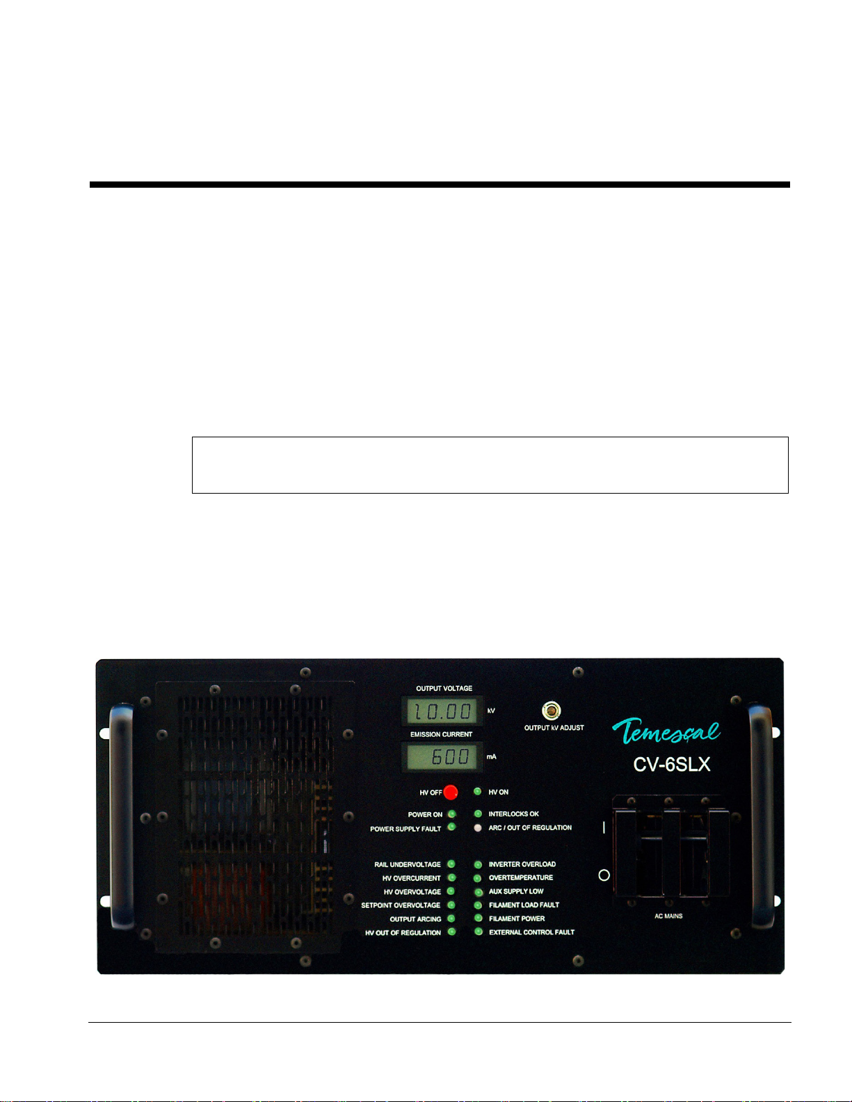
The Temescal Model CV-6SLX is a 6-kW, constant voltage, high-frequency, switching electron
beam power supply. The CV-6SLX is compatible with sources featuring either permanent-magnet
or electromagnetic deflection. The power supply delivers up to 10 kV at 600 mA, making it
possible to achieve substantial deposition rates in production environments. The CV-6SLX
provides stable output at all voltage levels, rapid arc recovery, ease of integration, and safety
and convenience for operating as well as service personnel.
The main components of CV-6SLX units are the HVPS (see Figure 1-1), the filament power
supply (see Figure 1-2), and the control and high-voltage cables required to connect these
components to each other and to the system’s control computer.
NOTE
In systems without a PLC-based system controller, a TemEBeamTM Controller (see Figure 1-3 is a
required accessory for the CV-6SLX. For additional information about the EBC, see section 1.5.
1.2 CV-6SLX HVPS Description and Specifications
Figure 1-1 shows the front panel of the CV-6SLX power module, or HVPS. For a description of its
control and display features, see sections 3.2 and 5.2. For installation instructions, see section
2.3.
Figure 1-1 CV-6SLX HVPS Front Panel
1.3 Filament Power Supply Description and Specifications Section 1: Introduction to the CV-6SLX
CV-6SLX User Manual 0101-8242-0, Rev. C
1-2
HVPS Specifications
Dimensions
8.75 in. H × 19 in. W × 23 in. D
Weight: 61 lbs.
Input Power
208-V Model CV-6SLX
208 V ac +10% /–5%, 50/60 Hz, 27 A, 60 Hz
3-phase delta (4-wire)
400-V Model CV-6SLX
400 V ac +10% /–5%, 50/60 Hz, 15 A, 50 Hz
3-phase wye (5-wire, with neutral)
NOTE
Current capacities listed above are for the facility breaker supplying power to the HVPS
and include the AC power required for the FPS, whose power cable should always be
connected to the HVPS rear panel, not to a separate power drop.
High Voltage Output
6 kW at 10 kV max.
Fully adjustable 0–10 kV
Regulated to within ±5%
Beam Current
Fully adjustable, 0–600 mA dc
Regulated to within ±5%
Environmental Requirements
Must be free of corrosive vapors
Ambient temperature: 104° F (40° C) maximum
Humidity: 10%–90%, noncondensing
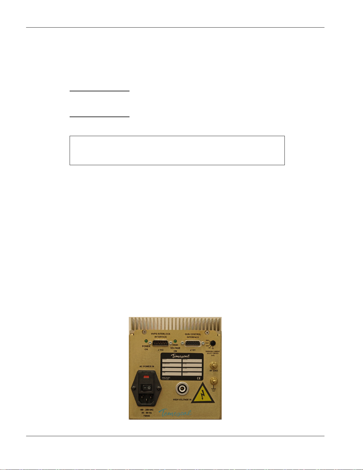
1.3 Filament Power Supply Description and Specifications
Figure 1-2 shows the filament power supply, a stand-alone assembly that must be installed near
the vacuum chamber.
Figure 1-2 Filament Power Supply Front Panel

Section 1: Introduction to the CV-6SLX 1.5 Miscellaneous Hardware and Interconnection Cables
0101-8242-0, Rev. C 1-3 CV-6SLX User Manual
For FPS installation instructions, see section 2.4. For a description of the switches and LEDs on
the FPS front panel, see section 3.3.
FPS Specifications
Dimensions: 6.5 in. H × 6.5 in. W × 11 in. D
Weight: 14 lbs.
Input Power: 208 V ac ±10%, 3.5 A, 50/60 Hz, single-phase
Power Output: 10 V ac, 50 A, 28.5 kHz (max.), single-phase
1.4 Miscellaneous Hardware and Interconnection Cables
For a complete list of the components and cables included with the CV-6SLX, see section 2.2.
1.5 TemEBeam Controller (EBC)
In systems without a PLC-based system controller, the TemEBeam Controller (see Figure 1-3)
provides the sole means of controlling the e-beam power supply. An EBC is therefore a required
accessory for the CV-6SLX in such systems. For detailed information about controlling the CV-
6SLX from the EBC, see section 3.5 of this manual. For complete information about installing
and operating the EBC see the EBC manual (PN 101-9028-0).
Figure 1-3 EBC Main Control Unit and Hand-Held Controller

1.5 TemEBeam Controller (EBC) Section 1: Introduction to the CV-6SLX
CV-6SLX User Manual 0101-8242-0, Rev. C
1-4

0101-8242-0, Rev. C 2-1 CV-6SLX User Manual
2 Installation
2.1 Section Overview
This section describes the procedures required for installation the CV-6SLX power supply. The
topics covered are:
Section 2.2 List of Components and Cables Supplied with the Unit
Section 2.3 Rack Mounting the Power Module (HVPS)
Section 2.4 Mounting the Filament Power Supply Module(s)
Section 2.5 Grounding Requirements
Section 2.6 Cable Installation
Section 2.6.1 Connecting the Input Power Cables
Section 2.6.2 Connecting the HV Coaxial Cable(s) (PN 0620-8684-1)
Section 2.6.3 Connecting the HV Output Conduit(s) (PN 0620-9654-1)
Section 2.6.4 Connecting the Control/Data Cables
Section 2.6.5 Making I/O Connections to the Vacuum System
CAUTION
Before beginning the installation procedure, make sure that the facility circuit breaker supplying
power to the CV-6SLX is switched OFF and locked out with an appropriate lockout/tagout device.
Also make sure that the FPS ON/OFF switch and the circuit breaker switch (labeled AC MAINS)
on the HVPS front panel are both in the OFF position. The facility breaker must remain locked and
tagged out during the entire installation procedure. Likewise, the power module’s main circuit
breaker switch and the FPS ON/OFF switch must both remain in the OFF position during the
entire installation procedure. The power-up procedure (see section 3.4) specifies the exact
sequence in which power should be applied to the unit.

2.2 List of Components and Cables Supplied with the Unit Section 2: Installation
CV-6SLX User Manual 0101-8242-0, Rev. C
2-2
2.2 List of Components and Cables Supplied with the Unit
Listed below are the components and cables supplied with CV-6SLX units.
•CV-6SLX HVPS, PN 0620-1135-0 (for 208-volt units) or 0620-1135-1 (for 400-volt units)
•Filament power supply, PN 0620-6604-0 or 0620-6604-2
•FPS input power cable, PN 6622-0100-20
•Terminal connector (PN 6149-1967-485) for user-supplied HVPS input power cable
•HVPS-FPS cable, PN 0620-6672-0
•HVPS I/O cable, PN 0620-6682-0
•FPS I/O cable, PN 0620-6672-2
•HV coaxial cable, PN 0620-8684-1
•HV cable/conduit assembly, PN 0620-9654-1
•Bracket (PN 0040-9982-0) for securing HV conduit to source tray
•16” grounding hook, PN 9900-4864-0
•20’ coil of 3”-wide copper strap, PN 5621-0032-3
•Coil of ½”-wide copper strap, PN 5621-0032-0
•One copy of CV-6SLX Technical manual
2.3 Rack Mounting the Power Module (HVPS)
2.3.1 General Installation Guidelines
The CV-6SLX HVPS can be rack mounted in a standard 19" rack cabinet. It must be supported
by two side shelf supports to hold the power supply weight. The rack vertical height required
is 8-3/4 inches. The chassis depth is 23 inches. An additional 3" is required for clearance of
terminals, plugs, and wiring. The panel should be secured to the rack cabinet by the four
mounting holes provided.
DANGER: HIGH VOLTAGE
Removal of the HVPS top cover can expose personnel to dangerous or lethal voltages.
Particular care should be taken regarding high voltage, which can arc over a considerable
distance. It is not necessary to be in physical contact with a live terminal in order for an arc to
send a lethal high-voltage discharge through a person’s body.
The HVPS is designed to be installed in an indoor laboratory or clean room in which the
immediate environment is controlled to maintain an ambient temperature of 40°C or lower
and a noncondensing humidity level of 10%-90%. Together, the screen covering the front
panel air vent plus the screen sandwiched between the exhaust fan and the rear panel
provides IP40 ingress protection. These screens prevent solid foreign objects larger than 1
mm in diameter from penetrating the outside chassis but do not provide a barrier against
liquids. Both screens must be removed and cleaned whenever the fan airflow drops more than
15% from its original value or every two years, whichever comes first. The power module
does not require any routine maintenance, aside from the cleaning of the screens.
2.3.2 Air Flow Requirements
The inverters have a temperature sensor that will shut down and latch out further operation if
an overtemperature condition should occur. The customer must ensure a free flow of air is

Section 2: Installation 2.4 Mounting the Filament Power Supply Module(s)
0101-8242-0, Rev. C 2-3 CV-6SLX User Manual
maintained through the cabinet and keep the ambient air temperature at the input to the
power supply below 104°F (40°C). All air passages must be unobstructed. If air filters are
used on the cabinet air input, they should be checked on a regular schedule for dirt and dust
accumulation.
CAUTION
Cabinet doors and panels must not block air vents located on the unit’s front and rear panels,
providing at least 2” of clearance from these vents. A fan located on the rear panel pulls air in
through the vents on the front panel, and exhausts warmer air through the rear vent.
2.4 Mounting the Filament Power Supply Module(s)
Install the FPS module(s) in the vacuum cubicle, within 6 feet of the high-voltage feedthoughs
that supply power to the e-beam gun. To do so, first drill four holes at the installation
location, in the pattern shown in Figure 2-1. Then place the holes in the bottom of the FPS
module over the drilled holes and secure the FPS in place with the hardware provided.
DANGER: HIGH VOLTAGE
Removal of any of the covers on the FPS module can expose personnel to dangerous or lethal
voltages. Particular care should be taken regarding high voltage, which can arc over a
considerable distance. It is not necessary to be in physical contact with a live terminal in order
for an arc to send a lethal high-voltage discharge through a person’s body.
Figure 2-1 Mounting Hole Pattern for FPS Module(s)
2.5 Grounding Requirements
2.5.1 Facility Low-Impedance Grounding Requirements
Safe, dependable operation of the power supply cannot be ensured unless a good earth
ground is provided for the system and the power supply. This ground must provide a low-
impedance path for radio frequency (RF) as well as direct current (dc) electricity, and it must
not be connected to that of any other system or equipment. Figure 2-2 shows two different
methods of providing the required low-impedance ground on the facility side of the
installation.

2.5 Grounding Requirements Section 2: Installation
CV-6SLX User Manual 0101-8242-0, Rev. C
2-4
Figure 2-2 Facility Low Impedance Grounding Requirements
The installation of twin rods of copper-clad steel is preferred. However, if the equipment is to
be installed on the upper floors of a building, the system can be grounded by connecting the
vacuum chamber to the steel structure of the building. Where copper straps are attached to
frame members, the copper must be bolted to clean, bare patches of metal. The length of
copper strap connected to the source tray must be securely bolted to a clean site on that part.
CAUTION
Do not use braided wire for any ground connections.
CAUTION
Do not rely on water pipes to establish the system ground connection. Multiple
plumbing joints, each with tape and/or sealing compounds, make such a ground
unreliable.
Table of contents
Other ferrotec Power Supply manuals


Popular Power Supply manuals by other brands

PairGain
PairGain HLU-611 Quick installation guide

Baldwin Boxall
Baldwin Boxall BVSMP installation manual

ABB
ABB NES48-23-AC1-PS4-DC1E-LVBD quick start guide

TDK
TDK ZACT-ME Series Specification sheet

Siemens
Siemens COMPS installation instructions

Broadcast Electronics
Broadcast Electronics Marti Electronics ME-40 manual


