Festo Pneumatic DRQ- *** - PPV-A Series User manual
254 655
Operating instructions
Pneumatic
rotary
drive
Bedienungsanleitung
Pneumatischer
Drehantrieb
Type DRQ- .
.
.
-
PPV-A
DRQ-...-PPVJ-A
Typ DRQ- .
.
.
-
PPV-A
DRQ-... -PPVJ-A
PPV
‘ .
.
PPVJ
Conditions regarding the use of
Fest0
This is important for reasons of safety
equipment
1.
It
is most important that only properly instructed and
qualified personnel use this equipment.
2. This equipment should only be used within the limits
detailed in the technical specification. Stritt observance of
’
the technical specification should be ensured at all times.
3. Correctly prepared compressed
air
should be
tised
at
all times. When installing the equipment and thereafter, the
Customer shall ensure that the environmental conditions at
the place of use are taken into consideration.
4. If the equipment is incorporated in a
System
or used
within safety devices or circuits. the Customer shall ensure
that national and
local
safety laws and regulations are
ob-
served.
5. Should you require
further
information please contact
your
local
Festo Office.
These instructions are impottant. Please keep them in
a safe place.
Was ist beim Einsatz von
Fest0
Elementen zu
Die Einhaltung der jeweils angegebenen Grenzwerte für
beachten?
Drücke, Spannungen, Temperaturen und die Beachtung
von Hinweisen ist Voraussetzung für die ordnungsgemäße
Funktion und daher vom Anwender unbedingt zu gewähr-
leisten.
Es ist auf den Betrieb mit ordnungsgemäß aufbereiteter
Druckluft ohne aggressive Medien zu achten. Außerdem
sind die jeweiligen Umweltbedingungen am Einsatzort zu
berücksichtigen.
Bei Anwendung von
Feste.
Elementen im Sicherheitsbe-
reich sind stets auch die
jeweiligenvorschriften
der Berufs-
genossenschaft und des Technischen
Uberwachungs-
Vereins bzw. die entsprechenden nationalen Bestimmun-
gen zu beachten.
.
,
I

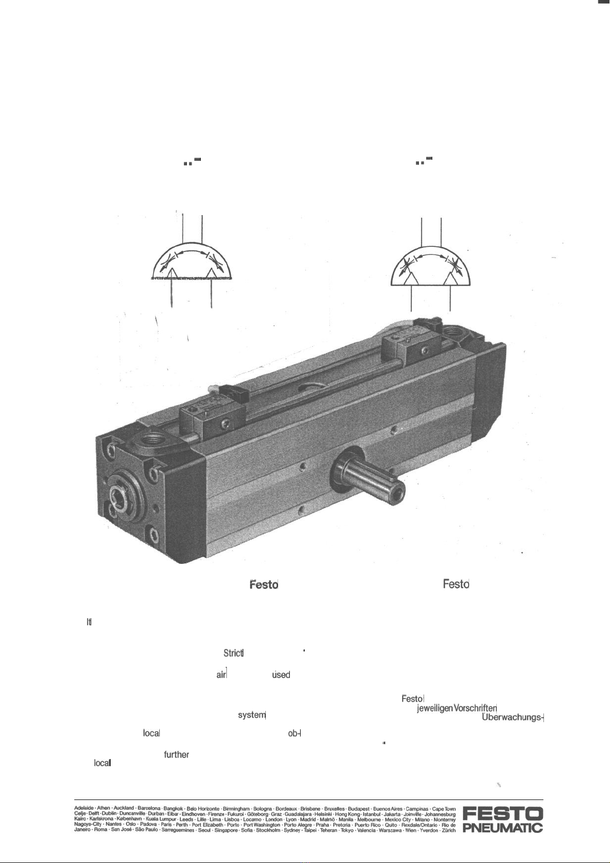
1.
Operating
park
and connections
1. Bedienteile und Anschlüsse
@
Thread for attachment
@Thread for attachment
(Concealed internal location)
@Thread for mounting
bracket
@
Adjusting screw for adjustment of the
rotation angle
Only with DRQ-.
.
.
-PPVJ-A)
@Setting screw for end
Position
cushioning (concealed internal location)
@
Inlet
pressure
port
@
Mounting rail for end
Position
sensing
@Drive shaft
@Thread for end
Position
adjustment
@
Centering countersink
2.Technical
data
2. Technische Daten
@Gewinde zur Befestigung
@Gewinde zur Befestigung
’
II
(verdeckt liegend)
c
@Gewinde für
Fu.ßbefestigung
@
Justierschraube für Drehwinkel-
.
einstellung (nur bei DRQ-.
.
.
-PPVJ-A)
@Einstellschraube für Endlagendämpfung
(verdeckt innenliegend)
@
Anschluß Druckluft
,-
@
Befestigungsleiste für Endlagenabfrage
,
@
Abtriebswelle
@Gewinde zum Gegenhalten der Masse
@
Zentriersenkung
Type
1
TYP
DRQ-40-PPVJ-A
DRQ-50:PPVJ-A
DRQ-63-PPVJ-A DRQ-80-PPVJ-A DRQ-1 OO-PPVJ-A
DRQ-40-PPV-A
DRQ-50-PPV-A
DRQ-63-PPV-A
DRQ-80-PPV-A
DRQ-l OO-PPV-A
Medium Compressed air, filtered, lubricated or unlubricated
/
gefilterte, geölte oder gefilterte, ungeölte Druckluft
Design
/
Bauart Double-acting
cylinder
with off-set rotary
pinion
in modular design
/
doppeltwirkender Zylinder mit exzentrischer Abtriebswelle in Baukastenkonstruktion
Assembly
Position
/
Einbaulage
Optional /beliebig
Axial load
/
zul. Belastung axial
l50N
300 N
500 N IOOON
1500N
of radial drive shaft
/
60N
200 N
3OON
800 N
1500N
der Antriebswelle radial
Torque at 6 bar
/
9Nm 19Nm
37 Nm
75Nm
.
150 Nm
Drehmoment bei 6 bar
Permissible mass
0,005
kgm2
0,016
kgm2
0,04
kgm*
0,12
kgm’0,2
kgm*
moment of
inertia*)
/
zul.
Massenträgheits-
moment*)
Operating pressure 2.5 to 10 bar
/
2,5
bis 10 bar
range
/
Betriebsdruckbereich
Temperature range
/
-1Oto+60deg.C/-lObis+60”C
Temperaturbereich
Materials
/
Werkstoffe Profile material: anodised aluminium; Cover: GU-AI,
anodised;
Gear
rack:
steel; Pinnion: hardened
/
Profilmaterial: Al-eloxiert; Deckel: GK-AI, eloxiert;
Zahnstange: Stahl; Ritzel: einsatzgehärtet
I
.*)Applies
odlyto
movement against cushioning air pockets
l
) nur gültig für das Fahren gegen
Dämpfungs-Luftpolster
FESTO
PNEUMNIC
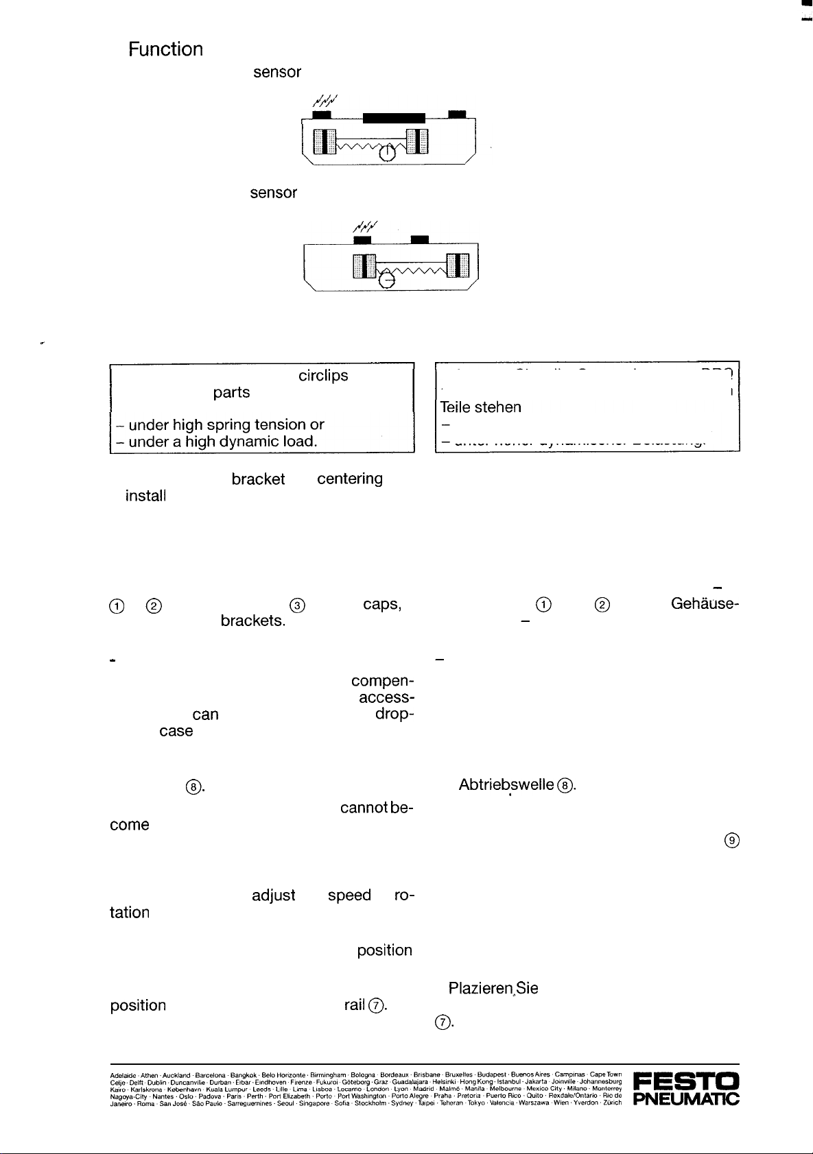
3.
Function 3. Funktion
a) External proximity
Sensor
a) Näherungsschalter außen
b) Internal proximity
Sensor
b) Näherungsschalter innen
-
4. Installation
4. Einbau
l
D
O
not disturb any of the
circlips
fitted on
the DRQ. The
Parts
retained by these are
l
Lassen Sie alle Sprengringe am DRQ
festgeklemmt. Die von ihnen gehaltenen
unter hoher Federspannung oder
unter hoher dynamischer Belastung.
l
Use a mounting bracket or a centering ring
to install the DRQ (see accessories)
l
Verwenden Sie zum Einbau des DRQ ggf.
Fußbefestigungen oder einen Zentrierring
(siehe Zubehör).
l
Ensure when positioning the DRQ, that the
l
Plazieren Sie den DRQ so, daß Sie stets die
setting facilities are accessible at all times.
Bedienteile erreichen können.
l
Attach using the threaded holes in the base
@
or @on drive side or in @the end
taps,
if
using mounting brackets.
l
Drehen Sie die Befestigungsschrauben
-
in
die Gewinde @oder
@
an den Gehäuse-
längsseiten,
-
oder in ③bei Verwendung von
Fußbefestigungen.
-
For off-set loads:
l
Check whether a compressed air
compen-
sating reservoir is required (see access-
ories). This
tan
prevent the load from
drop-
ping in case of a sudden fall in pressure.
-
Bei exzentrischen Massen:
l
Prüfen Sie die Notwendigkeit eines Druck-
luft-Ausgleichsspeichers (siehe Zubehör).
Bei schlagartigem Druckabfall können Sie so
vermeiden, daß die Masse nach unten
schlägt.
l
Secure the load to be moved to the output
drive shaft
@.
l
Make sure that the load secured
cannot
be-
come detatched from the output drive shaft.
Use the thread ➈in the output drive shaft to
do this.
l
Stecken Sie die zu bewegende Masse auf
die
Abtriebswelle
@.
l
Stellen Sie sicher, daß die aufgesteckte
Masse nicht von der Abtriebswelle gleiten
‘kann. Verwenden Sie hierzu das Gewinde
@
in der Abtriebswelle.
l
Use one-way flow control valves or quick
exhaust valves to adjust the
Speed
of ro-
tation (see accessories).
l
Use proximity Sensors for end Position
sensing (see accessories).
l
Attach the proximity Sensors for end
Position sensing on the mounting
rail
0.
l
Verwenden Sie Drosselrückschlagventile
oder Schnellentlüftungsventile zur Regulie-
rung der Drehgeschwindigkeit (siehe Zube-
hör).
l
Verwenden Sie Näherungsschalter zur Ab-
frage der Endlagen lt. Zubehör.
l
PlazierenSie
die Näherungsschalter für die
Endlagenabfrage auf der Befestigungsleiste
0.
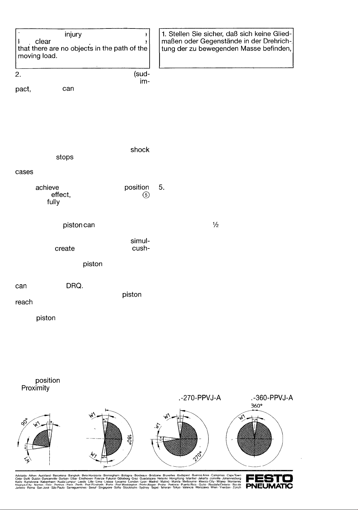
5. Commissioning
1.
To prevent injury or material darnage
keep clear of the rotary drive and ensure
2.
Please note that shock-type stress (sud-
den temperature Change, mechanical im-
patt,
Vibration)
tan
reduce the Service life of
the DRQ.
3. Check that the operating conditions are
within the permitted range. The permissible
mass moment of inertia must not exceed the
values specified (see technical data). This
should be calculated beforehand!
4. Check whether devices such as
shock
absorbers or Stops are required for external
cushioning of the moving load. Applies in
cases of large, fast movig loads.
5. To achieve the maximum end Position
cushioning effect,both adjusting screws
@
should be
fully
screwed-in on both sides.
6. Now turn back the setting screws ➎ half-
way so that the Piston
tan
move.
7. Pressurise both connections simul-
taneously to create an air cushion for cush-
ioning on both sides.
8. Makesure that the Piston always moves
against an air cushion, otherwise the load
resulting from the mass moment of inertia
tan
darnage the
DRQ.
9. Exhaust one connection for the
Piston
to
resch one end Position.
10. Alternate pressurising of the connections
for the
Piston
to move to and fro.
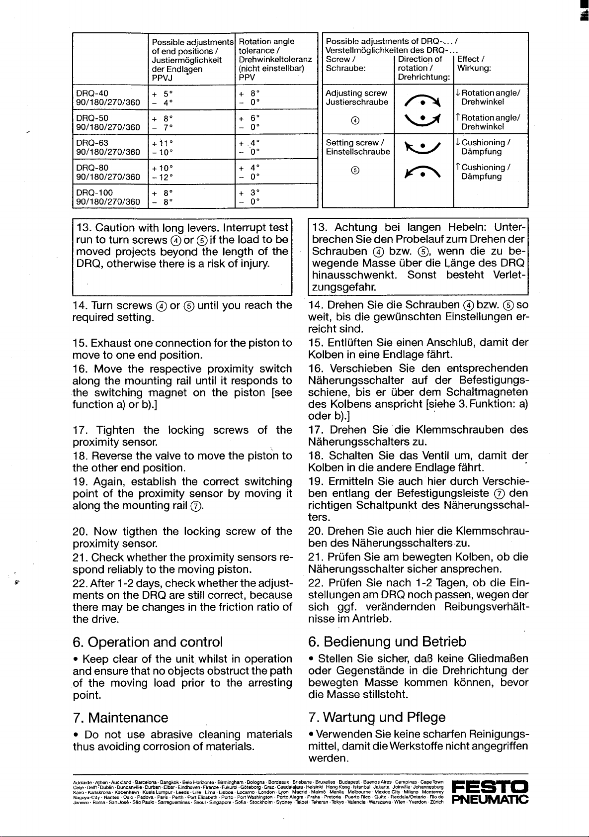
11. Check whether the angle of rotation and
cushioning are as required. If not, proceed as
follows:
12. Set the DRQ in the following order-:
5. Inbetriebnahme
um Schaden an Mensch und Material aus-
zuschließen (z.B. Schutzgitter).
2. Beachten Sie, daß schockartige Bean-
spruchung (Temperaturschock, mech.
Stöße, Vibration) die Lebensdauer des DRQ
herabsetzen kann.
3. Vergewissern Sie sich, daß die Betriebs-
bedingungen im zulässigen Bereich liegen.
Das Massenträgheitsmoment darf die vor-
gegebenen Werte nicht überschreiten (siehe
Technische Daten). Es sollte berechnet wor-
den sein!
4. Prüfen Sie, ob Vorrichtungen notwendig
sind (Stoßdämpfer, Anschläge), um die be-
wegte Masse extern abzufangen. Das ist der
Fall, wenn große Massen schnell bewegt
werden.
5.
Drehen Sie die Einstellschrauben @für die
Endlagendämpfung auf beiden Seiten ganz
ein, damit die maximale Dämpfungswirkung
erreicht wird.
6. Drehen Sie die Einstellschrauben ➎ dann
beidseitig wieder
‘15
Umdrehung zurück, da-
mit der Kolben bewegbar bleibt.
7. Belüften Sie beide Anschlüsse gleichzei-
tig. Dadurch wird beidseitig ein Luftpolster
für die Dämpfung aufgebaut.
8. Stellen Sie sicher, daß der Kolben stets
gegen ein Luftpolster fährt, sonst kann die
Belastung durch das Massenträgheitsmo-
ment zur Zerstörung des DRQ führen.
9. Entlüften Sie einen Anschluß, damit der
Kolben eine Endlage erreicht.
10. Belüften Sie wechselweise die An-
schlüsse, so daß sich der Kolben hin und her
bewegt.
11. Prüfen Sie, ob der Drehwinkel und die
Dämpfung passen. Wenn nicht, gehen Sie
wie folgt vor:
12. Stellen Sie den DRQ in der angegebenen
Reihenfolge ein:
l
Drehwinkel
l
Endlagendämpfung
l
Näherungsschalter.
DRQ-. .
.-270-PPVJ-A
DRQ-. .
.-360-PPVJ-A
360°
l
Angle of rotation
l
End Position cushioning
l
Proximity
Sensors
DRQ-...-90-PPVJ-A DRQ-...-180-PPVJ-A
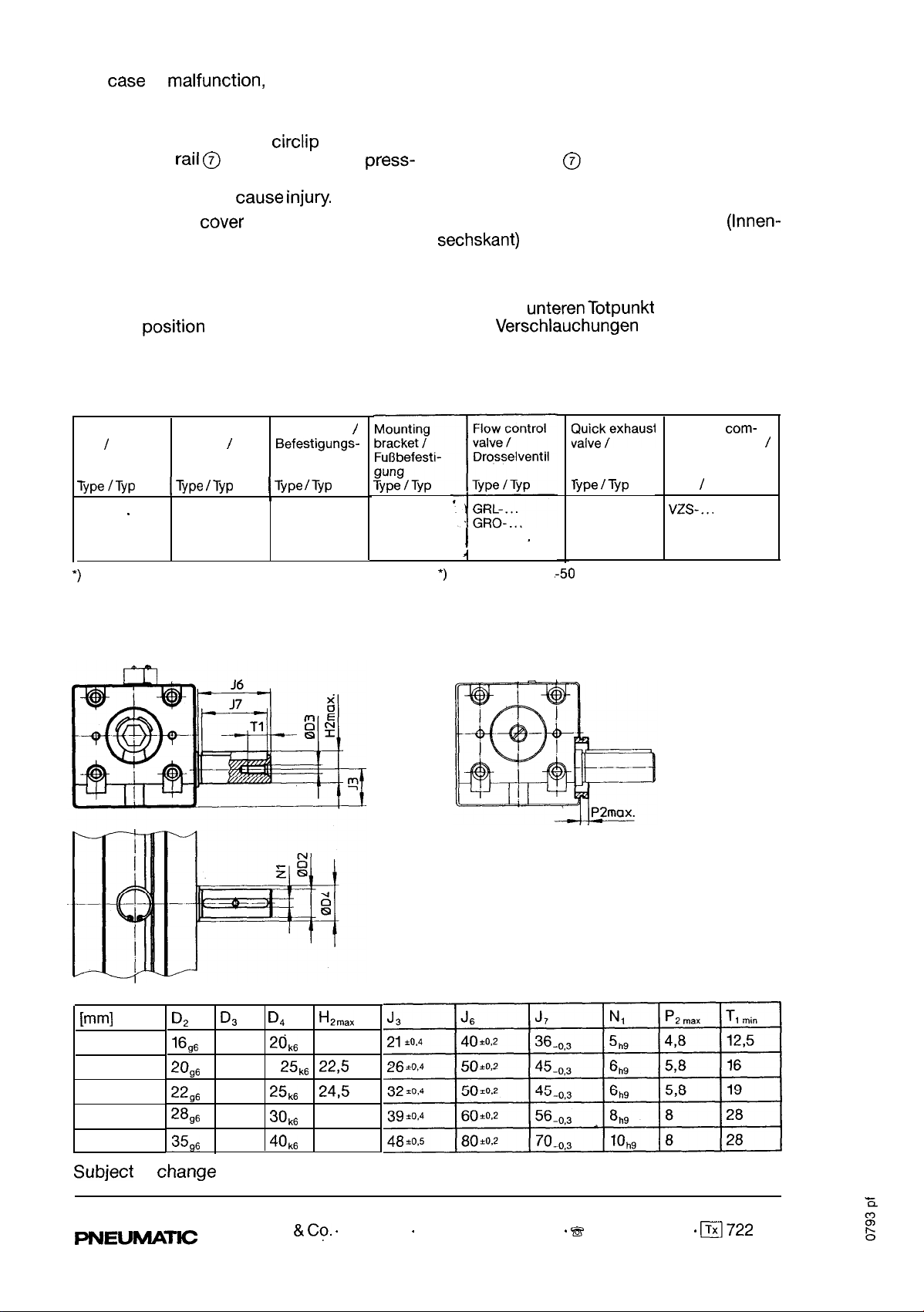
8. Repairs
l
In
case
of
malfunction,
return your DRQ to
Festo. D
O
not attempt to carry out your own
repairs.
l
D
O
not tarnper wih the
circlip
adjacent to
the mounting
rail
@as this retains the press-
ure pad. Sudden release of the high initial
spring tension could
Cause
injury.
l
Leave the end cover screws (Allen screws)
tigthened; these are secured with Loctite.
l
Exhaust both connections.
l
Please ensure that off-set loads are in the
lowered Position before disconnecting the
tubing.
8. Ausbau
l
Senden Sie den DRQ zu Festo ein, falls er
nicht mehr ordnungsgemäß funktioniert.
Reparieren Sie nicht selbst.
l
Lassen Sie den Sprengring neben der
Be-
festigungsleiste @zu,
zur Vermeidung von
Unfällen. Der von ihm gehaltene Deckel steht
unter hoher Federvorspannung.
l
Lassen Sie die Deckelschrauben
(Innen-
sechskant)
zu. Sie sind mit Loctite gesichert.
l
Entlüften Sie beide Anschlüsse.
l
Stellen Sie sicher, daß sich exzentrische
Massen im
UnterenTotpunkt
befinden, bevor
Sie die
Verschlauchurigen
lösen.
9. Accessories 9. Zubehör
Centering
ring
/
Zentrierring
Proximity
Sensors
l
Näherungs-
Schalter
Mounting kit
/
Befestigungs-
bausatz
Type
/VP
1
Type
/TYP
1
Type
/TYP
I
ZBRQ-.
.
SMEO-1 SMB-1
SMPO-1
-H-B*)
SMTO-1
‘)nur für DRQ-40, -50
HQ-...
10. Dimensional drawing of drive
shaft
I
GRPO-.
.
1
GRPL-...
*)
only for DRQ-40,
.-50
[mml
D,
D,
D,
f-L,mx
DRQ-40
16,6
M5
20,,
18
DRQ-50
20g6
M6
2&
22,5
DRQ-63
22,6
M8
25k6
24,5
DRQ-80
28,6
M12
30ks
31
DRQ-100
35,6
M12
40k6
38
Subject
to
Change
LIa2fek,exhaust
Schnellentlüf-
tungsventil
Type
/TYP
SEU-...
SE-...
Pressure com-
pensating valve
/
Druckausgleichs-
ventil
Type
1
T
YP
vzs-...
10. Maßzeichnung Antriebswelle
Änderungen vorbehalten
FEST0
FVUEUMATKZ
Festo AG
&
Co.
.
Postfach
.
D-73726 Esslingen
-
B
(07 11) 347-0
.
(Txl722 727
This manual suits for next models
12
Table of contents
Other Festo Pneumatic DC Drive manuals

Popular DC Drive manuals by other brands


Danfoss
Danfoss 176F6636 installation instructions

Eaton
Eaton DX-NET-PROFINET-2 manual

Ametek
Ametek Dunkermotoren BGE 6060 A EC Operation manual

ABB
ABB ACS355 series Quick installation and start-up guide

YASKAWA
YASKAWA P1000 Safety precautions

Piezoconcept
Piezoconcept HS1 Installation and operation manual