Festo Pneumatic FRC-E-**-S-B Series User manual

Operating Instructions
for Service Unit
Combination
Type FRC-E- .
.
.
-S-B
321 240
(182
535)
Bedienungsanleitung
ftir
Wartungsgerate-
Kombination
Typ FRC-E-.
.
.-S-B
ConditionsregardingtheuseofFesto
This is important for reasons of safety
equipment.
I
It
1s
most Important that only properly
wtructed
and
quaIlfled
personnel use
this
equ,pment.
2
This
equjpment
should only be used
wIthIn
the
llrnlts
detaIled
in
the technical
speciflcatlon.
Strict
observance of
the technical
speclf!catlon
should be ensured at all
times.
3.
Correctly prepared compressed
w
should be used at
all
t,mes.
When #nsM!ng the
equ,pment
and thereafter. the
Customershallensurethat
theenwronmental
conditionsat
the place of use
are
taken
,“to
corwderahon.
4 if the
eqwpment
1s
mcorporated
an
a
system or used
wIthIn
safety devices or
c(rcuIts,
the
Customer shall ensure
that national and local safety laws and regulations
are
ob-
served.
5. Should you require further
mformatton
please contact
your local Festo
office.
These instructions are important. Please keep them in
a
safe place.
DIG
Einhaltung
der
~ewe~ls
angegebenen
Grenzwerte
fur
Was ist beim
Einsatz
vonFestoElementen
zu
Drixke,
Temperaturen
und
die
Beachtung
“on
H~nweisen
1st
Voraussetzung
fur
die
ordnungsgemal3e
Funktion
und
beachten?
daher
“on-
Anwender
unbedmgt
ZL.
gew~hrkasten
Es
1st
auf den
Betrleb
rntt
ordnungsgemal3
aufbwateter
Druckluft
ohne
aggresswe
MedIe”
zu
achbzn.
Auflerdem
and
die
jewe~l!gen
Umweltbedmgungen
am
Elnsatzort
zu
bertickxhtlgen.
Be1
Anwendung
van
Festo
Elementen
rr
Slcherheltsbe-
wch
smd
stets
such
d~eiewelllgenVorschr~ften
der
Berufs-
genossenschaft
und
des
Techmschen
Uberwachungs-
Veretns
bzw.
die
entsprechenden
nattonalen
Besttmmun-
gen zu
beachten

1. Operating parts and connections
1.
@
I
a
Pressure
adjustrng
knob
@Oil droplet adjusting screw
@
011
droplet
vrewrng
glass
(3
Pressure relieving
~$8
Elecmcal
connection for
solenord
valve
@Safety start-up valve
@Gradual build-up of pressure at supply port
@Manual override
@
Exhaust
@
Fiegulattng
screw for
setting
the pressure
Increase
@
Cover plate
@
Lubricator
a
Condensate drain screw
@Central supply port
2. Technical data
2. Technische Daten
Bedienteile und
Anschkisse
Please note:
If the filter bowl is damaged
whilst pressurized, personnel
could be injured.
For safety reasons we recom-
mend the fitting of a metal
bowl guard.
Bitte beachten:
Bei
mechanischer
Beschadi-
gung der
tmter
Druck
stehen-
den
Filterschale
besteht
Ver-
letzungsgefahr
fur das Per-
sonal.
Aus
Sicherheitsgmnden
ist
deshalb die Verwendung
van
Metaiischutzkorben
zu emp-
fehlen.
a
Druck-Einstellknopf
@
Dltropfen-Einstellschraube
@
Oltropfen-Schauglas
@
Druckentluftung
g’el.
Anschlu6 fur
Magnetventil
3
Stcherheits-Einschaltventil
@
Druckluftanschlu6
mit langsamem
Druckaufbau
@
Handhilfsbetatigung
@
Entltiftung
@
Ftegulrerschraube
fur die Einstellung des
Druckaufbaus
@
Abdeckschild
@
Oler
@
Kondensat-Ablaflschraube
@!
Zentraler
Druckluftanschlul3
Comolete
unit
/
Komolette
Einhert
Type ITyp
FFiC-E-‘/d-S-B
FIX-E-Y-S-B
FRC-E-%-S-B
Part No.
/Teile-Nr.
32 930
32 931
32 932
Medium Compressed
arr
/
Druckluft
Pressure range
/
Druckbereich
Supply pressure
p,
/
Erngangsdruck
p,
min.
2 bar
1
30 psi
max. 10 bar
/
150
psf
Output pressure
pT
/Ausgangsdruck
p2
max.
IO
bar
/
150 psi
Rated flow
/
Nenndurchflul3
l/mm
650 930 1770
Temperature range
/Temperaturbereiche
Medium temperature
1
Medtum-Temperatur
14to140°F/-lOto+60%-10bis+60°C
Ambienttemperature/Umgebungs-Temperatur
23 to 104
OF/-
5
to
+40
‘C
/
-
5 bis
+40
“C
Materrals
/
Werkstoffe
Housing: Polyamide; Seals:
NBR;
Connections:
Brass; Bowls: Polyamide
(TrogamrdeT);
Filter element: Sintered element
(PE-HD)
/
Gehause:
Polyamid;
Dichtungen:
NBR;
Anschlusse: Messing; Schalen: Polyamid
(Trogamid
T);
Filterpatrone:
Sinterpatrone
PE-HD

3. Assembly
3. Montage
When several units are combined connector mod-
ules should be used between every second unit to
ensure secure
mountrng.
-
remove cover plate
-
insert and tighten screws
-
replace cover plate
-
connect supply and output lines.
Wenn mehrere Module miteinander
verbunden
werden,
wird
zur
sicheren Befestigung an jeder
zwerten
Ernhert
verschraubt.
-
Abdeckschild abnehmen
-
Schrauben
einsetzen
und
anziehen
-
Abdeckschild einsetzen
-
Ein-
und
Ausgangslertungen
anschliegen.
Safety start-up valve
Check that the operating voltage is comparable
with the solenoid voltage.
-
Connect
solenord
@
-
Pull out manual override
@
and turn to secure (to
prevent inadvertent engagement).
Turn regulating screw
@
clockwise to its limit
-
(&&I;~,
start-up slowly open the regulating
Sicherheits-Einschaltventil
anschliegen
uberprufen,
ob Betnebsspannung mit der
Spulen-
spannung
iiberernstimmt.
-
Magnetspule
anschlrefien
@
-
Handhilfsbetatrgung
herausziehen
und
drehen
(Sicherung gegen
ungewolltes
Einrticken)
@
-
Regulierschraube
im
Uhrzetgersinn
ganz
zudre-
hen
@
(Bet
lnbetriebnahme
Regukerschraube
langsam
offnen)
Note:
Hinweis:
A module support can be used for
sacure
mounting
of large (more than 3)
combmatrons
of units.
GX:
Order no. 32937
Type
LFFVFRC-MT%S-B
G%:
Order no. 32938
Type LFFVFRC-MT%-S-B
G%:
Order no. 32939
Type
LFR/FRC-MT%S-B
Otherwise, bracket type HR-. -S-B can be used
for mounting,
Bei
umfangreichen
Kombinationen
(mehr
als
3
Ge-
rate) kann
zur
sicheren Montage
ein
Modultrager
verwendet
werden.
GX:
Bestellbezeichnung 32937
Typ
LFRIFRC-MT%S-B
G%:
Bestellbezeichnung 32933
Typ
LFRIFRC-MT%-S-B
GX:
Bestellbezeichnung 32939
Typ
LFR/FRC-MT’&S-B
Ansonsten sind fur die Montage
Befestigungswin-
kel
Typ
HR-.
S-B
au
verwenden.
4. Commissioning 4. lnbetriebnahme
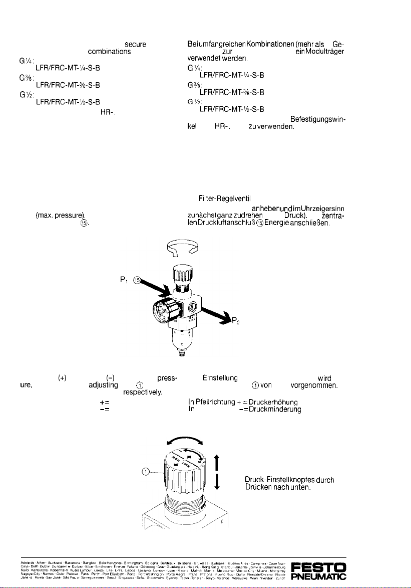
4.1 Filter regulator
4.1 Filter-Regelventil
Turn the pressure adjusting knob clockwise to its
limit
(max.pressure).
Attach a supply line to the Druck-Einstellknopf anheben
und
im
Uhrzeigersinn
central supply port
‘3.
zunachst
ganz zudrehen (max.
Druck).
Am
zentra-
len
Druckluftanschlul3
@
Energie
anschlier3en.
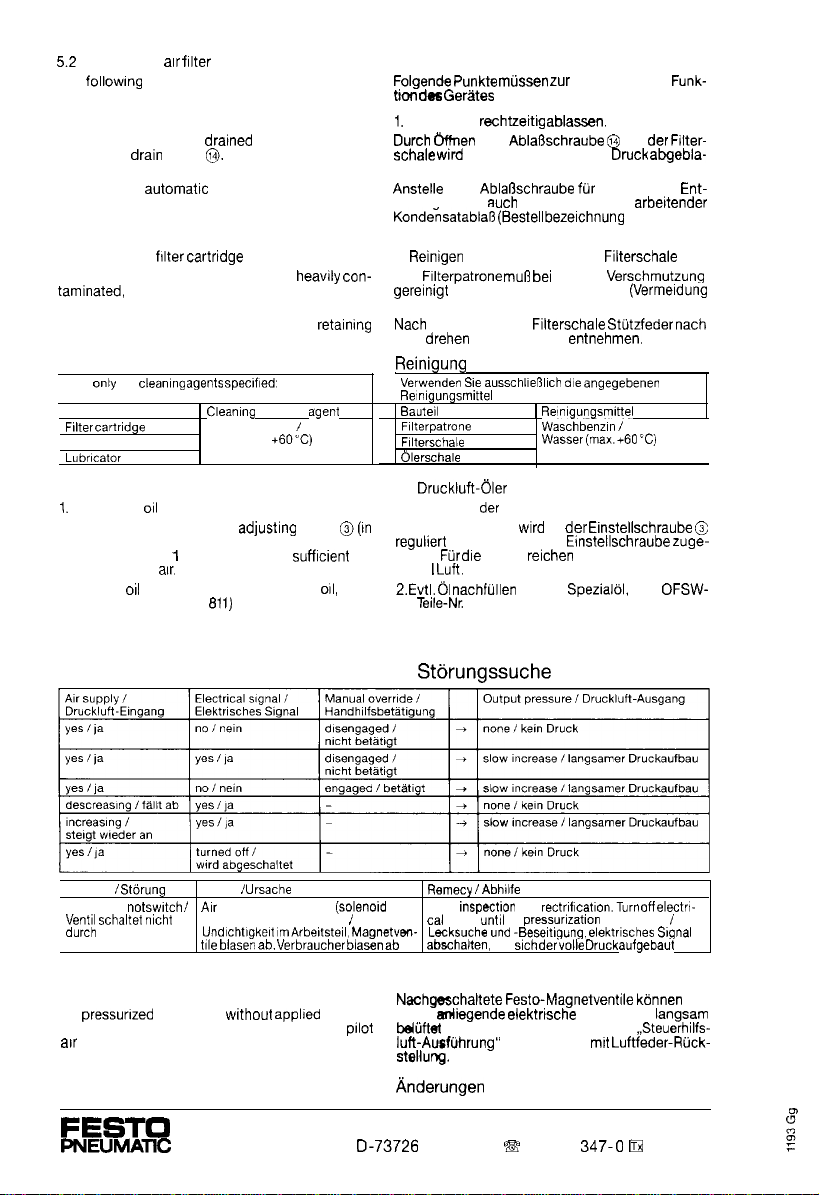
To increase
(+)
or decrease
(-)
the operating
press-
ure,
turn the pressure
adjustrng
knob
e
clockwise Die
Etnstellung
des Betriebsdruckes
wird
am
(see arrow), or counterclockwise
respectrvely.
Druck-Einstellknopf
avon
oben
vorgenommen.
When the arrow points to
+
=
pressure Increases
When the arrow points to
-
=
pressure decreases
In
Pfeilrrchtung
+
=
Druckerhohung
In
Pfeilnchtung
-
=
Druckminderung
Lock the pressure
adjusting knob by pressing
downwards.
t
1
Arretieren des
Druck-Einstellknopfes
durch
Dnicken
nach
unten.

4.2 Safety switch-on valve 4.2 Sicherheitseinschaltventil
Setting the regulating screw
@
Einstellung
der
Regulierschraube
@
a) Calculate flow
bef
b1
a) Durchflu5
ermitteln
tv
=
Full-flow
t,me
delay
V
=
Downstream
reservar
D
=
Flow rate through
flow
control valve
P,
=
Full-flow
!xessure
P:
=
Supply
p;eswre
P>
=
Outlet
preswre
Full-flow pressures
P”
MFHEA/LHE-..:%
0
2468
10 12
-PI
bor-
b
=
Durchschaltzeltverz~gerung
=
nachgeschaltetesVolumen
D
=
DurchfluB
der
Drosselung
P
d=
Durchschaltdruck
P,
=
Spewdruck
P*
=
Ausgangsdruck
Durchschaltdrucke
P
MFHE’VLHE-.
-%
MFHE/VLHE-.
.:‘/z
0 2 4
6 8
10 12
-P,
bor-
0 2 4
6 8
10 12
-PI
bor-
b)Take note of the number of
revolutrons
of
regulat-
b)
Umdrehungszahl
der
Regulrerschraube($(Dros-
ing @(flow control screw) selschraube)
ablesen
Flow rate through flow control valve
Durchfltisse
D
der
Drosselung
MFHE/VLHE-.
-‘A
MFHE/VLHE-.
-Ye
MFHE/VLHE-.
-j/z
Note:
Hinweis:
If the manual override
83
is set, it is automatically
re-
Die
gedruckte
Handhilfsbetatrgung
@
fahrt
berm
set when the valve is actuated by a control
srgnal.
Ansteuern
desventrls
durch
ein Steuersignal auto
matisch
heraus.
5.
Operation and maintenance
5. Bedienung und Wartung
5.1 Safety switch-on valve
5.1
Sicherheitseinschaltventil
The safety start-up valve
1s
maintenance free.
When a muffler is used, contamination build-up
Das
Sicherheits-Einschaltventil ist wartungsfrei.
Bei
eingesetzten
Schalld&mpfern
von Zeit
.zu
Zeit
should be monitored, and the muffler replaced Verschmutzungsgrad
kontrollteren.
Bei
.
Bedarf
when necessary.
Schalldampfer
auswechseln.
5.2 Druckluft-Filter
Folgende
Punkte
mussen
zur
einwandfreien
Funk-
tion
des
Gerates
beachtet werden:
1.
Kondensat rechtzethg
ablassen.
Durch
&men
der
AblaSschraube
@
an
der
Filter-
schale wird das Kondensat unter Druck
abgebia-
sen.
5.2
Compressed air
filter
The
followtng
procedures should be observed for
trouble free operation of the service unit:
1. Condensate blow-off.
Condensate should be dratned at regular intervals
by opening
drain
screw
@.
Condensate will be blown off under pressure.
If desired, an automatkc condensate drain may be
Installed (order no. 101 844 Type WA-l).
2. Cleaning the
falter
cartndge
and bowl
If the filter cartridge becomes
heawly
con-
tamlnated,
it must be cleaned or replaced to avoid
a drop in output pressure.
After removing the filter bowl, turn the
retainrng
spring to the left and remove the filter.
Cleaning
Use
only
the
cleamng
agwts
spec#f!ed:
Component
Filter
cartrIdge
Filter bowl
Lubwator
bowl
cleamng
agem
Petroleum ether
I
water (max.
+6O’C)
5.3 Cleaning the filter bowl
1.
Setting the
oil
droplet rate
Droplet rate is controlled by
adjusting
screw
@(In
closed positron when delivered). For normal oper-
ating conditions Ito 12 drops are
sufficient
for
every 1000 L of
air.
2. Top-up
orl
as necessary (Festo special
011,
Type
2
Evtl.
01
nachfullen
(Festo Spezialol, Typ
OFSW-
OFSW-32, Part. No. 152
811)
32,
Teile-Nr.
152811)
6. Safety start-up valve
trouble shooting
Anstelle der
Ablaflschraube
fur manuelle Ent-
leeruna kann such ein automatisch
arbettender
Konde:satablaR
(Bestellbeze~chnung
101844 Typ
WA-l) eingeschraubt werden.
2.
Reinigen
von Filterpatrone und
Fiiterschale
Die
Fllterpatrone
mug
bei
starker
Verschmutzung
gereinigt
oder ausgewechselt werden
(Vermeldung
von Leistungsabfall).
Nach
Entfernen der
Fllterschale
Stutzfeder
nach
links
drehen
und Sinterfilter
entnehmen
Reinigung
Verwenden
Sic
ausschlMl~ch
die
angegebenw
Rengungsmittel
Baute1l
1
Re~n~gungsm~ttel
F~lterpatrwe
Fllterschale
&?rschale
Waschbenzln
I
Wasser
(max.+60
‘C)
5.3
Druckluft-oler
1. Einstellung
der
Tropfenmenge
Die Tropfenmenge wlrd an der
Einstellschraube
@
reguliert
(Lieferzustand:
Ejnstellschraube
zuge-
dreht).
Fur
die
Praxis
reIchen
1 bis 12 Tropfen auf
1000
I
Luft.
6. Sicherheits-Einschaltventil
SCrungssuche
Problem
I
Stdrung
Cause
1
Ursache Remecy
/Abh!lfe
Valve does
not
swtch
I
AIM
leakage downstream
(solerwd
Leak
inspectnn
and
rectr~f~cat~on.Turn
off
electrw
Vent11
schaltet
mcht
valves, other components) /cal signal
until
full
pressurization
is achieved
I
durch
tJnd!chtlgkelt
lmArbe#tstell,
Magnetven-
Lecksuche
und
-Beseltlgung.
elektrlsches
SIgnal
tfle
bIasen
ab,
Vwbraucher
blasen
ab
abschalten,
bis
such
der
voile
Druck
aufgebaut
hat
Note: Hinweis:
Festo solenoid valves connected downsteam can
Nachgeschaltete
Festo-Magnetventile
konnen
nur
be
pressurized
slowly only
wtthout
appljed voltage. ohne
diegende
elektnsche
Spannung
langsam
Exceptions to this are those with the auxiliary
prlot
b&ftet
werden.Ausnahme:Ventile in
Steuerhilfs-
arr
design, and valves with pneumatic spring reset.
luft-Ausfuhrung”
und Ventile
mtt
Luftfeder-Rick-
stellung.
Subject to change
Anderungen
vorbehalten
FESTO
PNEUMATKZ
Festo KG Postfach
II-73726
Esslingen
B
(0711)
347-0
Pi
722727
This manual suits for next models
3
Table of contents
Popular Water Filtration System manuals by other brands

Hayward
Hayward XStream Manuel du propriétaire

Applied Membranes
Applied Membranes L Series Operation, maintenance & instruction manual

WaterLogic
WaterLogic WL270 Service manual

Pentair
Pentair FLECK 5800 SXT Service manual

Yamato
Yamato WS 200 instruction manual

amiad
amiad Filtomat MG-110P Installation, operation and maintenance instructions


