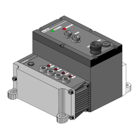
Festo Compact Performance CP-FB9-E Owner's manual

Compact Performance
CP fieldbus node 13
Programming and diagnosis
fieldbus protocol:
PROFIBUS-DP as per EN 50170 (DIN 19245)

Author: H.-J. Drung
Editors: H.-J. Drung, M. Holder
Translation: D. Smith
Layout: Festo, Dept. KI-TD
Type setting: DUCOM
Edition: 9904b
(Festo AG & Co., 73726 Esslingen,
Federal Republic of Germany, 1998)
The copying, distribution and utilization of this docu-
ment as well as the communication of its contents to
others without expressed authorization is prohibited. Of-
fenders will be held liable for the payment of damages.
All rights reserved, in particular the right to carry out
patent, utility model or ornamental design registration.
Printed on 100% recycled paper
Contents and general safety instructions
CP FB13-E 9904b I

Order no.: 165 213
Title: Manual
Designation:P.BE CP-FB13-E-GB
Contents and general safety instructions
II CP FB13-E 9904b

Contents
Designated use. . . . . . . . . . . . . . . . . . . . . . . . . . . . . . . . . . . . . . . . . . . . . . V
Target group. . . . . . . . . . . . . . . . . . . . . . . . . . . . . . . . . . . . . . . . . . . . . . . . V
Information on this manual . . . . . . . . . . . . . . . . . . . . . . . . . . . . . . . . . . . VI
Important user instructions . . . . . . . . . . . . . . . . . . . . . . . . . . . . . . . . . . . VII
1. Installation
1.1 General instructions . . . . . . . . . . . . . . . . . . . . . . . . . . . . . . . . . . . 1-3
1.2 Setting the DIL switches . . . . . . . . . . . . . . . . . . . . . . . . . . . . . . . 1-4
1.2.2 Setting the fieldbus address. . . . . . . . . . . . . . . . . . . . . . . . . . . . 1-7
1.3 Fieldbus baud rate and fieldbus length . . . . . . . . . . . . . . . . . . . 1-10
1.3.1 Branch line length. . . . . . . . . . . . . . . . . . . . . . . . . . . . . . . . . . . . 1-11
1.4 Connecting CP modules . . . . . . . . . . . . . . . . . . . . . . . . . . . . . . 1-12
1.5 Connecting the operating voltage . . . . . . . . . . . . . . . . . . . . . . . 1-13
1.6 Connecting the PROFIBUS DP interface . . . . . . . . . . . . . . . . . 1-14
1.6.1 Connecting the screening. . . . . . . . . . . . . . . . . . . . . . . . . . . . . 1-15
1.6.2 Bus termination with terminating resistors . . . . . . . . . . . . . . . 1-16
1.6.3 Optical fibre waveguide connection . . . . . . . . . . . . . . . . . . . . . 1-18
2. Commissioning
2.1 Preparing the CP system for operation
on the PROFIBUS-DP . . . . . . . . . . . . . . . . . . . . . . . . . . . . . . . . 2-3
2.1.1 Operating voltage . . . . . . . . . . . . . . . . . . . . . . . . . . . . . . . . . . . 2-3
2.1.2 Saving the string assignment. . . . . . . . . . . . . . . . . . . . . . . . . . . 2-3
2.1.3 Compiling the configuration list . . . . . . . . . . . . . . . . . . . . . . . . . 2-5
2.1.4 General. . . . . . . . . . . . . . . . . . . . . . . . . . . . . . . . . . . . . . . . . . . . 2-6
2.2 Configuration with a Siemens master . . . . . . . . . . . . . . . . . . . . 2-13
2.2.1 COM PROFIBUS . . . . . . . . . . . . . . . . . . . . . . . . . . . . . . . . . . . 2-13
2.2.2 STEP 7 V4.x - Hardware configurator . . . . . . . . . . . . . . . . . . . 2-20
2.2.3 Commissioning the CP system on the PROFIBUS-DP. . . . . . 2-30
Contents and general safety instructions
CP FB13-E 9904b III

2.3 Operation with general DP master . . . . . . . . . . . . . . . . . . . . . 2-32
2.3.1 Starting the bus . . . . . . . . . . . . . . . . . . . . . . . . . . . . . . . . . . . . 2-32
2.3.2 Sending parametrizing data . . . . . . . . . . . . . . . . . . . . . . . . . . 2-33
2.3.3 Sending configuration data. . . . . . . . . . . . . . . . . . . . . . . . . . . . 2-35
2.3.4 Requesting diagnostic information . . . . . . . . . . . . . . . . . . . . . 2-36
2.3.5 Cyclic exchange of data . . . . . . . . . . . . . . . . . . . . . . . . . . . . . 2-36
2.3.6 Summary of implemented functions and
service access points (SAP) . . . . . . . . . . . . . . . . . . . . . . . . . . 2-38
2.3.7 Bus parameters/reaction times. . . . . . . . . . . . . . . . . . . . . . . . . 2-39
2.3.8 Transmission times on the PROFIBUS-DP . . . . . . . . . . . . . . . 2-39
2.4 Type file and device master file (GSD) . . . . . . . . . . . . . . . . . . 2-40
3. Diagnosis
3.1 LED displays on the bus node . . . . . . . . . . . . . . . . . . . . . . . . . 3-3
3.1.1 Normal operating status . . . . . . . . . . . . . . . . . . . . . . . . . . . . . . 3-4
3.1.2 Diagnosis operating voltage POWER or POWER V . . . . . . . . . 3-5
3.1.3 Diagnosis LED BUS ERROR. . . . . . . . . . . . . . . . . . . . . . . . . . . 3-6
3.2 Testing the valves . . . . . . . . . . . . . . . . . . . . . . . . . . . . . . . . . . . 3-7
3.3 Diagnosis via PROFIBUS-DP. . . . . . . . . . . . . . . . . . . . . . . . . . . 3-9
3.3.1 Diagnostic words . . . . . . . . . . . . . . . . . . . . . . . . . . . . . . . . . . . . 3-9
3.3.2 Diagnostic information . . . . . . . . . . . . . . . . . . . . . . . . . . . . . . . 3-12
3.4 Error treatment . . . . . . . . . . . . . . . . . . . . . . . . . . . . . . . . . . . . 3-17
3.4.1 General DP master. . . . . . . . . . . . . . . . . . . . . . . . . . . . . . . . . . 3-18
3.4.2 Siemens SIMATIC S5/S7 . . . . . . . . . . . . . . . . . . . . . . . . . . . . . 3-18
3.5 STEP 7 V4.x - Online diagnosis via diagnostic buffer. . . . . . . 3-21
3.6 Short circuit/overload . . . . . . . . . . . . . . . . . . . . . . . . . . . . . . . . 3-24
3.6.1 Output module . . . . . . . . . . . . . . . . . . . . . . . . . . . . . . . . . . . . . 3-24
3.6.2 Sensor supply at an input module . . . . . . . . . . . . . . . . . . . . . . 3-25
A. Technical specifications
A.1 Technical specifications of fieldbus node CP FB13-E. . . . . . . . A-3
A.2 Index. . . . . . . . . . . . . . . . . . . . . . . . . . . . . . . . . . . . . . . . . . . . . . A-5
Contents and general safety instructions
IV CP FB13-E 9904b

Designated use
The CP fieldbus node CP-FB9-E documented in this
manual is designated exclusively for use as a slave on
the PROFIBUS-DP. Festo CP modules can be con-
nected to the fieldbus node CP-FB9-E. The CP node
may only be used as follows:
– as designated
– in original condition
– without unauthorized modifications
– in faultless technical condition.
The specified limit values for pressures, temperatures,
electrical data, moments, etc. must be observed when
additional commercially-available components such as
sensors and actuators are connected. Please comply
also with national and local safety laws and regulations.
Target group
This manual is directed exclusively at technicians who
are trained in control and automation technology and
who have experience in installing, commissioning, pro-
gramming and diagnosing PROFIBUS-DP slaves.
Contents and general safety instructions
CP FB13-E 9904b V

Information on this manual
This manual contains specific information on the instal-
lation, commissioning, programming and diagnosis of
the CP fieldbus node 13 for PROFIBUS-DP as per EN
50170 (DIN 19245).
Enclosed with this manual is a CD ROM with device
master files. Information on the contents can be found
in the file "readme".
Information on further CP modules can be found in the
relevant manual. This is summarized in a table further
in this chapter.
Contents and general safety instructions
VI CP FB13-E 9904b

Important user instructions
This manual contains instructions on the dangers which
may occur if the CP system is not used correctly. These
instructions are always printed in italics, are framed and
also signalled by pictograms.
Danger
categories
A distinction is made between the following:
WARNING
This means that personal injury or damage to
property may occur if these instructions are not
observed.
CAUTION
This means that damage to property may occur if
these instructions are not observed.
PLEASE NOTE
This means that this instruction must also be
observed.
Contents and general safety instructions
CP FB13-E 9904b VII

Pictograms and symbols complement the danger warn-
ings and draw attention to the nature and conse-
quences of dangers.
Pictograms
The following pictograms are used:
Uncontrolled movements of loose tubing.
Unintentional movements of the connected actuators.
High electric voltage or undefined voltage states of the
electronic components which can affect connected cir-
cutis.
Electrostatically vulnerable components.
These will be damaged if you touch the contact
surfaces.
•• This mark indicates activities which can be carried
out in any order.
Text
markings
1. Figures indicate activities which must be carried out
in the numerical order of the figures.
– Hyphens indicate general items.
Contents and general safety instructions
VIII CP FB13-E 9904b

Manuals for the CP system Peripherals
Manual "CP system, Installation and commissioning"
Contents General, basic information on operating, fitting, installing
and commissioning CP systems.
Manual "CP field bus node,
programming and
diagnosis"
"CPA valve terminal,
pneumatics" or
"CPV valve terminal,
pneumatics"
"CP modules,
electronics"
Contents Special information
on commissioning,
programming and
diagnosing related to
the node used.
Information on fitting,
installing and com-
missioning CPA or
CPV valve terminals
Information on
fitting,
installing and
commissioning
CP I/O modules
Fig. 0/1: Manuals on the CP system
AA
AA
AA
AA
AA
AA
AAAA
AAAA
AAAA
AAAA
A
A
A
A
AA
AA
AA
AA
AA
AA
AA
AA
AA
AA
AA
A
A
A
AA
AA
AA
AA
AAAA
AAAA
AAAA
A
A
A
Contents and general safety instructions
CP FB13-E 9904b IX

The following product-specific terms and abbreviations
are used in this manual:
Term/
abbreviation Meaning
Busy bit Release bit to analyze the data transfer with the CP system
CP cable Special cable for connecting the various CP modules
CP connection Socket or plug on the CP modules, with which the modules are
connected to the node by means of the CP cables
CP modules Common term for the various modules which can be incorporated
in a CP system
CP system Complete system consisting of CP fieldbus node and CP modules
I Digital input
I/O module Common term for the CP modules which provide digital inputs and
outputs (CP input and CP output modules)
I/Os Digital inputs and outputs
Node CP fieldbus node with/without fieldbus connection, to which the
I/O modules are connected
Octet Number of address words reserved by the CP system
O Digital output
PLC/IPC Programmable logic controller/industrial PC
Save
(SAVE buttons) Save the current string assignment (connected I/Os);
when the CP system is started the saved string assignment is compared
with the current string assignment.
If these differ the LEDs will blink.
String Total number of I/O modules that are connected to one common
CP connection on the fieldbus node
String
assignment Total of all I/O modules that are connected to a CP fieldbus node
via strings (0..3)
Contents and general safety instructions
XCP FB13-E 9904b

Chapter 1
Installation
1. Installation
CP-FB13-E 9904b 1-1

Contents
1. Installation
1.1 General instructions . . . . . . . . . . . . . . . . . . . . . . . . . . . . . . . . . . 1-3
1.2 Setting the DIL switches. . . . . . . . . . . . . . . . . . . . . . . . . . . . . . . 1-4
1.2.2 Setting the fieldbus address. . . . . . . . . . . . . . . . . . . . . . . . . . . . 1-6
1.3 Fieldbus baud rate and fieldbus length . . . . . . . . . . . . . . . . . . . 1-9
1.3.1 Branch line lenght. . . . . . . . . . . . . . . . . . . . . . . . . . . . . . . . . . . 1-10
1.4 Connecting CP modules. . . . . . . . . . . . . . . . . . . . . . . . . . . . . . 1-11
1.5 Connecting the operating voltage. . . . . . . . . . . . . . . . . . . . . . . 1-12
1.6 Connecting the PROFIBUS DP interface . . . . . . . . . . . . . . . 1-13
1.6.1 Connecting the screening. . . . . . . . . . . . . . . . . . . . . . . . . . . . . 1-14
1.6.2 Bus termination with terminating resistors . . . . . . . . . . . . . . . 1-15
1.6.3 Optical fibre waveguide connection . . . . . . . . . . . . . . . . . . . . . 1-17
1. Installation
1-2 CP FB13-E 9904b

1.1 General instructions
WARNING
Before starting installation or maintenance work,
switch off the following:
•
the compressed air supply
•
the operating voltage on the fieldbus node
(pins 1 and 2)
•
the load voltage for the valves
You thereby avoid:
– uncontrolled movements of loose tubing.
– unintentional movements of the connected actuators.
– undefined switching states of the electronic
components.
CAUTION
The node of the CP system contains electrostatically
vulnerable components.
•
Do not, therefore, touch any components.
•
Please observe the regulations for dealing
with electrostatically vulnerable components.
In this way you will avoid irreparable damage to the
electronic components on the node.
General information on the installation of the CP
modules can be found in the manual "CP system".
1. Installation
CP-FB13-E 9904b 1-3

1.2 Setting the DIL switches
The DIL (dual in-line) switch is situated under the cover
of the fieldbus node.
You should open and close the cover as follows:
•To open the cover, unscrew the two screws in the
cover. Remove the cover by lifting it up.
•To close the cover, replace it and tighten the screws
again by hand.
PLEASE NOTE
Tighten the screws of the switch cover only by hand.
WARNING
•
Before commissioning:
Make sure that switch elements 3..6 are set
at PROFIBUS-DP.
•
During operation:
Do not modify the setting of the DIL switches.
In this way you can avoid unintentional reactions of the
connected actuators.
1. Installation
1-4 CP FB13-E 9904b

1
2
DIL switch
Cover screws
Fig. 1/1: Position of the DIL switch
2
1
1. Installation
CP-FB13-E 9904b 1-5

Set the following functions on the DIL switch:Dual in-line
switch – the hundreds figure of the fieldbus address
– the fieldbus protocol PROFIBUS-DP.
Switch elements 3..6 must be set at the position
specified below, in order that the fieldbus protocol
PROFIBUS-DP is set.
DIL switch
(factory
setting)
Switch
element Function description
1fieldbus address
ON: fieldbus address > 100
OFF: fieldbus address < 100
2Diagnostic information VValves/VOutputs
ON: active
OFF: not active
3Fieldbus protocol PROFIBUS-DP
ON: must be set at ON
OFF: reserved
4Fieldbus protocol
ON: must be set at ON
OFF: reserved
5Fieldbus protocol
ON: must be set at ON
OFF: reserved
6Fieldbus protocol
ON: reserved
OFF: must be set at OFF
1. Installation
1-6 CP FB13-E 9904b

1.2.2 Setting the fieldbus address
PLEASE NOTE
The fieldbus addresses of the CP system cannot be
modified by the DP master. The CP system can only
be addressed by the fieldbus addresses set on the
address selector switches.
1
2
3
Address selector switch UNITS figure
Address selector switch TENS figure
Address selector switch HUNDREDS figure
Fig. 1/2: Setting the fieldbus address on the
address selector switches
6
5
2
7890
1
3
4
6
5
2
7890
1
3
4
1
2
3
1. Installation
CP-FB13-E 9904b 1-7

Set the fieldbus address of the CP system with the two
round address selector switches and DIL switch el-
ement no. 1. The switches are numbered from 0..9. The
arrow indicates the units or tens figure of the fieldbus
address which is set.
Summary of possible fieldbus addresses
PLEASE NOTE
Fieldbus addresses may only be assigned once per
PROFIBUS-DP interface.
Observe also any restrictions concerning the
assignment of fieldbus addresses by your DP master.
Recommendation
Assign the fieldbus addresses in ascending order.
Adapt the station numbers to suit the machine structure
of your system.
Permitted fieldbus addresses 0; ... ; 125
1. Installation
1-8 CP FB13-E 9904b

Proceed as follows:
1. Switch off the operating voltage.
2. Assign an unused fieldbus address to the CP system.
3. Use a screwdriver to set the arrow of the relevant
address switch or DIL switch 1 to the units, tens or
hundreds figure of the desired fieldbus address.
Examples
Set fieldbus address Set fieldbus address
005 121
Fig. 1/3: Example of set fieldbus addresses
6
5
2
7890
1
3
4
6
5
2
7890
1
3
4
1. Installation
CP-FB13-E 9904b 1-9
Table of contents
Other Festo Network Hardware manuals
Popular Network Hardware manuals by other brands

Aperto
Aperto PacketWave 1000 Series Installation, configuration, and operation manual

Unex
Unex OBU-352 Series quick start guide

Zte
Zte ZXA10 C320 Hardware description

Net Optics
Net Optics BPO-SX installation guide

ADTRAN
ADTRAN NIU3 Installation and maintenance practice

Huawei
Huawei EchoLife HG8247H Quick start quide

Huawei
Huawei Airbridge BTS3606C Product description

ALIBI
ALIBI ALI-NVR71128R Setup guide

Huawei
Huawei MAP05A1 quick guide

Extreme Networks
Extreme Networks ExtremeWireless AP510e installation guide

Belkin
Belkin Dual-Band Wireless A+G USB Network Adapter... Specifications

Revox
Revox DVD Module 04 user manual