FHP CA CONSOLE series User manual

970-293 Revised 05-12
CA CONSOLE SERIES
Table of Contents
Model Nomenclature......................................................................................................1
Introduction .......................................................................................................................2
Safety Considerations.....................................................................................................2
Inspection, Moving & Storage.....................................................................................2
Installation..........................................................................................................................2
Piping ...................................................................................................................................3
Electrical ..............................................................................................................................3
Cooling Tower/Boiler Applications ...........................................................................3
Earth Coupled Applications ........................................................................................4
Maintenance ......................................................................................................................4
System Checkout .............................................................................................................4
Unit Start-Up......................................................................................................................4
Typical Wiring Diagram..................................................................................................5
Operating Temperatures & Pressures .......................................................................6
Unit Check-Out Sheet.....................................................................................................9
CUC Solid State Controller .........................................................................................10
MODEL NOMENCLATURE
SERIES:
CA - R-410A Refrigerant Slope Top
NOMINAL CAPACITY:
VOLTA E DESI NATION:
0 - 115/1/60
1 - 208/1/60 & 230/1/60
2 - 265/1/60
8 - 8-220-240/1/50
CONTROLS:
U - Manual/Auto Change Over (Unit Mounted)
R - Remote Thermostat
S - Master/Slave with Remote Thermostat
NOT USED
HEAT EXCHAN ER
C - Copper
N - Cupro-Nickel
WATER CONNECTION:
L - Left (Standard)
R - Right (Optional)
CA 012 -1UL C- XXX

970-293 Revised 05-12
INTRODUCTION:
The FHP console water source heat pumps are designed
for use as decentralized room terminals that are field
connected to a closed-circuit piping loop within a
structure. Typically these units are installed in perimeter
zones and are ideal for installations where ducted systems
are impractical.
All FHP Console Series units are designed for boiler/tower
systems geothermal closed loop applications and can
operate with fluid temperatures as low as 25°F in heating
and as high as 110°F in cooling. Units are available in 3/4,
1, 1-1/4 and 1-1/2 tons nominal capacity in cooling. Refer
to the unit specification sheet for precise performance
figures at various entering air and water conditions.
NOTE: Console units are designed for indoor installation
in the conditioned space only. Do not install outdoors, in
attics or in any other location that would subject the unit to
extreme temperature or humidity or to corrosive
environments. Doing so will inhibit performance, reliability
and service life of the unit.
SAFETY CONSIDERATIONS:
Installation and servicing of this system can be hazardous
due to system pressure, electrical components and
moving parts. Only trained and qualified service
personnel should install and service this equipment.
Untrained personnel can perform basic maintenance such
as cleaning coils/cabinet or replacing filters.
WARNING: Before performing service or maintenance
operations on system, turn off main power to unit. On
units with unit mounted controls, the On/Off switch DOES
NOT disconnect the unit from main power. High voltage
components or moving parts can cause injury or death.
When working on this equipment, always observe
precautions described in the literature, tags and labels
attached to the unit. Follow all safety codes. Wear safety
glasses and work gloves. Use a quenching cloth for
brazing operations and place a fire extinguisher close to
the work area.
This unit is designed to be operated with the cabinet,
subbase and filter in place. Never operate unit without the
cabinet and filter in place or with open access panels.
Doing so can expose the operator to hazardous voltage
and moving parts and can damage the equipment.
INITIAL INS ECTION, MOVING
AND STORAGE:
Inspect the carton or packaging of each console unit as it
is received at the job site and before signing the freight
bill. Note any damage or shortage on all copies of the
freight bill. Concealed damage must be reported to the
carrier within 24 hours of receipt.
Unit wiring diagrams and Installation/Operation manuals
are provided with each unit. Read these manuals prior to
start up to become familiar with the unit and its
operation.
Note that an Installation/start-up checklist is provided at
the end of this manual to encourage thorough unit check-
out at start-up.
Take care when moving the unit as most of the unit's
weight is located on the left (compressor) end. Always
store and move unit in an upright position. Take care to
protect the unit cabinet and subbase when moving or
storing. Never move or lift unit by its water connections.
If the equipment is not needed for immediate installation,
it should be stored in its original packaging in a clean, dry
area. Units must be moved and stored in an upright
position, never lay the unit on it's side. When storing, do
not stack units.
INSTALLATION:
Before installing the unit, examine each pipe, fitting and
valve; remove any dirt or debris found on or in these
components. Use care when installing the system
components to avoid damage to the cabinet finish or
chassis.
1. After removing the console unit from its packaging
remove the cabinet by removing the cabinet screws
on either side of the unit and lifting the cabinet off
the chassis. Set the cabinet aside and cover it (the
console unit’s packaging can be used for this
purpose).
2. Position the sub base directly on the finished floor.
Make sure the sub base is level (use shims if
necessary). The sub base has a frame that supports
the cabinet and may be secured to wall.
3. Position the chassis onto the sub base. Check and align
electrical, water and condensate connections and
secure to the sub base with 4 screws.
4. Before connecting the unit to water, make sure that
the loop has been properly flushed. After flushing the
system, connect piping or hoses to the proper supply,
return and condensate connections. Refer to the
piping section of this manual for more information
5. Make all necessary electrical connections to the unit.
Refer to the unit wiring diagram and the Electrical
section of this manual.
CAUTION: When making electrical connections to
the unit make sure that the power is disconnected.
Failure to do disconnect power before connecting
power wiring to the unit can result in serious injury or
death and damage to the unit.
6. Make sure the unit’s washable filter is clean and
installed in the subbase. Also make sure that the filter
clip is in place.
7. Reinstall the unit cabinet via locating pins at the top
of the chassis and two screws in the unit subbase.
2CA CONSOLE SERIES

970-293 Revised 05-12
I ING:
SU LY AND RETURN I ING:
The following items should be adhered to in addition to
applicable piping codes.
• A drain valve at the base of each riser to enable
proper flushing of the system at startup and during
servicing.
• Shut-off/Isolation ball valves at the supply and return
connections and unions at each unit to permit proper
flow balancing and unit servicing.
• Strainers at the inlet of each circulating pump.
• Use of teflon tape on threaded pipe fittings to
eliminate water leaks and insure against air entering
the system.
• Flexible hose connections between the unit and the
rigid system to eliminate the possibility of vibration
transmission through the piping.
• Insulation is not normally required on supply and
return piping for boiler tower installations except in
unheated sections or outdoor runs.
• Insulation is required for closed-loop geo-thermal
installations as loop temperatures may fall below the
dew point and can even fall below the freezing point
of water during heating season.
CONDENSATE I ING:
Console units are designed with a blow-through
configuration in the air handling section. This means that
there is positive pressure at the unit drain pan and thus
trapping is not required. Condensate is routed from the
drain pan via a 5/8" non-pressure rated vinyl hose that is
located below the supply and return water connections.
Though horizontal runs of condensate piping are usually
too short to pose problems, horizontal runs should be
pitched at least 1 inch for every 10 feet of piping. Avoid
low spots or unpitched piping, as these areas can collect
sediment and eventually block condensate flow.
Always inspect both internal and external condensate
piping for kinks that could block condensate flow.
HOSE KITS:
When using optional hose kits follow the manufacturer's
recommendations for installation. Never stretch or twist
hoses and never use hoses that show external wear or
damage or are suspected of having damage. Never exceed
the manufacturer's maximum working pressure
recommendations.
ELECTRICAL:
CAUTION: Use only copper conductors for field installed
electrical wiring. Always make sure that the power
disconnect is open before performing service on the
unit's electrical circuits.
Field wiring must comply with local and national fire,
safety and electrical codes. Power to the unit must be
within the operating voltage range indicated on the unit
chassis nameplate or the performance data sheet.
Properly sized fuses or HACR breakers must be installed
for branch circuit protection. See unit chassis name plate
for maximum size.
Each chassis is supplied with a 2 x 4 junction box for
power connection. Inside this box there are 2 pigtail leads
for power wiring. The field ground is to be connected to
the ground connection on the junction box.
On remote thermostat and master/slave units there are
also 5 position terminal blocks for low voltage thermostat
or slave unit connection. On remote thermostat units,
connect the thermostat wires to the low voltage terminal
block. On master/slave units connect the thermostat to
the “Master” terminal block of the lead unit and the “Slave”
terminal block to the “Master” terminal block of the next
unit, daisy chaining the units together as required. Note
that there is no limit to the number of units that can be
connected together in this manner as each unit provides
it's own low voltage power supply.
NOTE: All 208/230 volt (-1 voltage code) units are factory
wired to 230 volts unless ordered otherwise. In 208
voltage applications the transformer wiring may need to
be switched from the 230 volt tap to the 208 volt tap. Cap
all unused leads.
COOLING TOWER/BOILER A LICATIONS:
The cooling tower and boiler water loop temperature is
usually maintained between 50°F and 100°F to assure
adequate cooling and heating performance.
In the cooling mode, heat is rejected from the console
unit into the water loop. A cooling tower provides
evaporative cooling to the loop water thus maintaining a
constant supply water temperature to the unit. When
utilizing open cooling towers chemical water treatment is
mandatory to ensure the water is free from corrosive
elements. A secondary heat exchanger may also be used
between the unit and the cooling tower water. In closed
loop systems such as this it is imperative that all air be
removed from the closed side of the system to insure
against fouling of the heat pump water-to-refrigerant
heat exchanger.
In the heating mode, heat is absorbed from the loop by
the console unit. A boiler may be used to maintain the
loop at the desired temperature.
No unit should be connected to the supply or return
piping until the water system has been completely
cleaned and flushed to remove any dirt, piping chips or
3
CA CONSOLE SERIES

970-293 Revised 05-12
other foreign material. Supply and return hoses should be
connected together during this process to ensure the
entire system is properly flushed. After the cleaning and
flushing has taken place the unit may be connected to the
water loop and should have all valves wide open.
EARTH COU LED SYSTEMS:
Closed loop and pond applications require specialized
design knowledge. No attempt at these installations
should be made unless the contractor has received
specialized training.
Anti freeze solutions are utilized when low evaporating
conditions are expected to occur (I.E.: low loop
temperatures in heating). Typical temperatures are 30°F
fluid temperature in heating and 100°F in cooling.
MAINTENANCE:
1) Filter changes or cleanings are required at regular
intervals. The time period between filter changes will
depend upon type of environment the equipment is
used in. In a single family home, that is not under
construction, changing or cleaning the filter every 60
days is sufficient. In other applications, such as
motels, where daily vacuuming procedures a large
amount of lint, filter changes may need to be as
frequent as biweekly.
2) An annual “checkup” is recommended by a licensed
refrigeration mechanic. Recording the performance
measurements of volts,amps, and water temperature
differences (both heating and cooling) is
recommended. This data should be compared to the
information on the unit's data plate and the data
taken at the original startup of the equipment.
3) Lubrication of the blower motor is not required.
4) The condensate drain should be checked annually by
cleaning or flushing to insure proper drainage.
5) Periodic lockouts almost always are caused by air or
water flow problems. The lockout (shut down) of the
unit is a normal protective measure in the design of
the equipment. If continual lockouts occur call a
mechanic immediately and have them check for:
water flow problems, water temperature problems, air
flow problems or air temperature problems. Use of
the pressure and temperature charts for the unit may
be required to properly determine the cause.
SYSTEM CHECKOUT:
• After completing the installation, and before
energizing the unit, the following system checks
should be made:
• Verify that the supply voltage to the heat pump is in
accordance with the nameplate ratings.
• Make sure that all electrical connections are tight and
secure.
• Check the electrical fusing and wiring for the correct
size.
• Verify that the low voltage wiring between the
thermostat and the unit is correct.
• Verify that the water piping is complete and correct.
• Check that the water flow is correct, and adjust if
necessary.
• Check the blower for free rotation, and that it is
secured to the shaft.
• Verify that vibration isolation has been provided.
• Unit is serviceable. Be certain that all access panels
are secured in place.
UNIT START-U :
1. Set the thermostat to the highest setting.
2. Set the thermostat system switch to "COOL", and the
fan switch to the "AUTO" position. The reversing valve
solenoid should energize. The compressor and fan
should not run.
3. Reduce the thermostat setting approximately 5
degrees below the room temperature.
4. Verify the heat pump is operating in the cooling
mode.
5. Turn the thermostat system switch to the "OFF"
position. The unit should stop running and the
reversing valve should deenergize.
6. Leave the unit off for approximately (5) minutes to
allow for system equalization.
7. Turn the thermostat to the lowest setting.
8. Set the thermostat switch to "HEAT".
9. Increase the thermostat setting approximately 5
degrees above the room temperature.
10. Verify the heat pump is operating in the heating
mode.
11. Set the thermostat to maintain the desired space
temperature.
12. Check for vibrations, leaks, etc...
FREEZE SENSOR
This is optional and can be set to ignore or monitor a freeze
sensor.There are 2 configurable freeze points, 35°F & 15°F.
The unit will enter a soft lock out until the temperature
climbs above the set point and the anti-short cycle time
delay has expired. The freeze sensor may not provide
protection in the case of loss of flow in the heating mode.
A flow switch or pressure differential switch is
recommended to prevent unit operation in case of loss of
flow.
4CA CONSOLE SERIES

970-293 Revised 05-12
UNIT ROTECTION MODULE (U M)
The Unit Protection Module (UPM) as shown in figure 1, is
a printed circuit board (PCB) that interfaces with the
thermostat or the digital direct controller.
The main purpose of this device is to protect the
compressors by monitoring the different states of switches
and sensors of each refrigerant circuit, this device provides
time delays and protects the unit against freezing of the
water and refrigerant heat exchangers as well as condensate
overflow when the appropriate sensors are installed.
Figure1
t
Figure 1
Alarm output is Normally Open (NO) dry contact. If 24 VAC
output is needed R must be wired to the ALR-COM
terminal; 24VAC will be available on the ALR-OUT terminal
when the unit is in alarm condition. If pulse is selected the
alarm output will be pulsed.
OWER RANDOM START U
This feature prevents multiple units sharing same
electrical circuit or network from starting at the same
time.
It assures that Heat Pumps sharing the same electrical
circuit do not demand high inrush currents
simultaneously when starting back up after a power
failure.
If the controller has been completely powered down for
more than 28 milliseconds, a random delay is initiated
typically the unit will start between the time range of 270
and 300 seconds, this only if the controller is set to
normal operation (test switch set to NO).
In order for the random sequence to initiate the unit
power must be removed completely.
IM ORTANT: If the board is set to “TEST” mode through
the “TEST” DIP switch SW1 delay will be 10 seconds.
ANTI SHORT CYCLE DELAY
This feature protects the compressor short cycling if the Y
call is set and removed.
The anti short cycle delay is 300sec delay on break during
normal operation.
NOTE: If the board is set to test mode through the “TEST”
DIP switch the delay will be 5 seconds.
Y CALL
The UPM will energize the compressor’s output (CC) in an event
of a “Y” call from a thermostat or controller (after the random
start up and/or the anti short cycle delays have elapsed). Y
input terminal must be energized with a 24 VAC signal.
HIGH AND LOW RESSURE ROTECTION
The UPM monitors the state of the High and Low pressure
Switch inputs of each refrigerant circuit, HPC and LPC on the
board respectively, these switches must be closed in order
for the controller to energize the compressor output (CC).
The CC output will only be energized when the switches are
closed and the anti short cycle (and /or random start up
when applicable) has expired.
HIGH RESSURE ROTECTION
If the HPC switch is open upon a Y call the UPM will not
energize the CC output and therefore the compressor will
remain off, the fault LED will flash one (1) time for the HPC
and the alarm contact will remain off.
If the compressor is running in normal mode on a Y call
and the high pressure switch opens, the UPM will shut
down the compressor output and will keep it off until the
switch closes and the anti short cycle has expired. The
controller will keep track of the number of times the
switch opens, if within one (1) hour period the switch
opens the number of times set via the DIP switch the
controller will shut the compressor down and perform a
hard lockout condition under this condition the alarm
contact will be energized.
The UPM allows the user to configure the counts that the
HPC will be allowed to open within one hour before the
UPM performs a hard lockout on the compressor. The user
can select either two or four times by changing switch
four (4) on the DIP switch SW1 (shown on table 3) on the
UPM board.
LOW RESSURE ROTECTION
If the LPC switch is open upon a Y call the UPM will not
energize the CC output and therefore the compressor will
remain off, the fault LED will flash two (2) times for the LPC
and the alarm contact will remain off.
If the compressor is running in normal mode on a Y call and
the low pressure switch opens, the UPM will keep the
compressor running for two (2) minutes if the condition
remains after this period of time the compressor will shut
down and the UPM will start a soft lockout. The UPM will flash
two (2) times for the LPC. And the alarm contact will remain off.
5
CA CONSOLE SERIES
970-293 Revised 05-12
If the switch closes, the UPM will start the compressor
after the anti short cycle has expired UPM will energize
the compressor output.
IM ORTANT: To exit the hard lockout the controller must
be reset from the Y or R terminal by removing the power
from the selected terminal. The user can choose which will
be the reset point via the DIP switch SW1.
GROUND
The UPM controller takes its ground reference from the
unit chassis which is connected to the controller via the C-
ND spade terminal.
DI SWITCH SETTINGS
The DIP switch is used to configure most of the available
features of the UPM as follows:
• Alarm mode, Constant or Pulse
• Reset mode, Y signal or R signal
• Lockout mode, two (2) or four (4) Strikes
• Test mode, Normal or Test operation
The settings shown below are factory default for most
heat pump applications, however the Unit wiring diagram
is the ultimate guide for factory DIP switch default
settings (Figiure 2).
Figure 2
The following table is available on the UPM board as well
and it depicts the switch position and its associated
functionality.
Figure 3
SELECTABLE ALARM MODE
The UPM controller can be configured to have either a
constant signal or a pulse.
If constant (CONT) is selected the UPM will provide a
closed contact until the alarm is cleared.
If pulsed (PULSE) is selected the UPM will sequence the
alarm contact with the fault LED flashes.
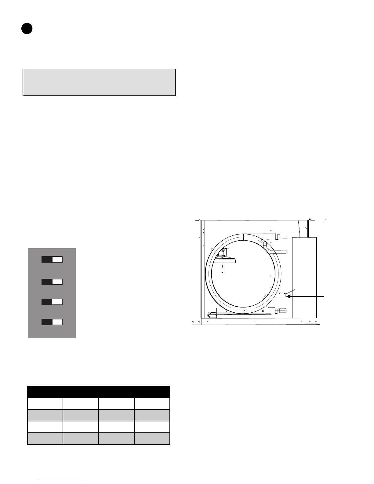
FREEZE ROTECTION
The default setting for the freeze limit trip is 30°F, however
this can be changed to 15°F by cutting the R42 resistor
located on top of the DIP switch SW1.
The UPM controller will constantly monitor the refrigerant
temperature with the sensor mounted close to the
condensing water coil between the thermal expansion
valve and water coil as shown in figure 4. If temperature
drops below or remains at the freeze limit trip for 30
seconds, the controller will shut the compressor down and
enter into a soft lockout condition. Both the status LED
and the Alarm contact will be active. The LED will flash
(three (3) times) the code associated with this alarm
condition.
Figure 4 Freeze rotection Sensor
BROWNOUT ROTECTION
The UPM controller will constantly monitor the power
supply, if the nominal voltage drops below 25% of its
value. (18 VAC approximately), the unit will enter
brownout protection mode. The compressor CC output
will be de-energized and the unit will enter the soft
lockout mode.
The controller will not monitor the power supply during
the first 500 milliseconds of compressor start up to avoid
noise and false alarms.
Once the UPM detects a brownout condition its fault LED
will flash five (5) times as error code indication.
Freeze
Protection
Sensor
1 2 3 4
ON
Lockout
Reset
Alarm
Test
6CA CONSOLE SERIES
UPM Dip Switch Configuration
4 LOCKOUT 4 2
3 RESET R Y
2 ALARM CONT PULSE
1 TEST YES NO

970-293 Revised 05-12
CONDENSATION OVERFLOW
The UPM controller continuously monitors the drain pan
for high condensate water level, and to do so it utilizes a
sensor and identifies an alarm condition when the
sensor’s impedance drops below 230KΩ +/- 15 % (ONLY
when condensate sensor option is present). Once the UPM
senses this resistance value it enters into a hard lockout
and reports the correspondent code via its status LED (4
flashes).
To exit the hard lockout water has to return to its normal
level the UPM has to be reset by removing the power from
the Y terminal (R if set on the DIP switch) the compressors
will be turned on after anti short cycle expires.
7
CA CONSOLE SERIES
970-293 Revised 05-12
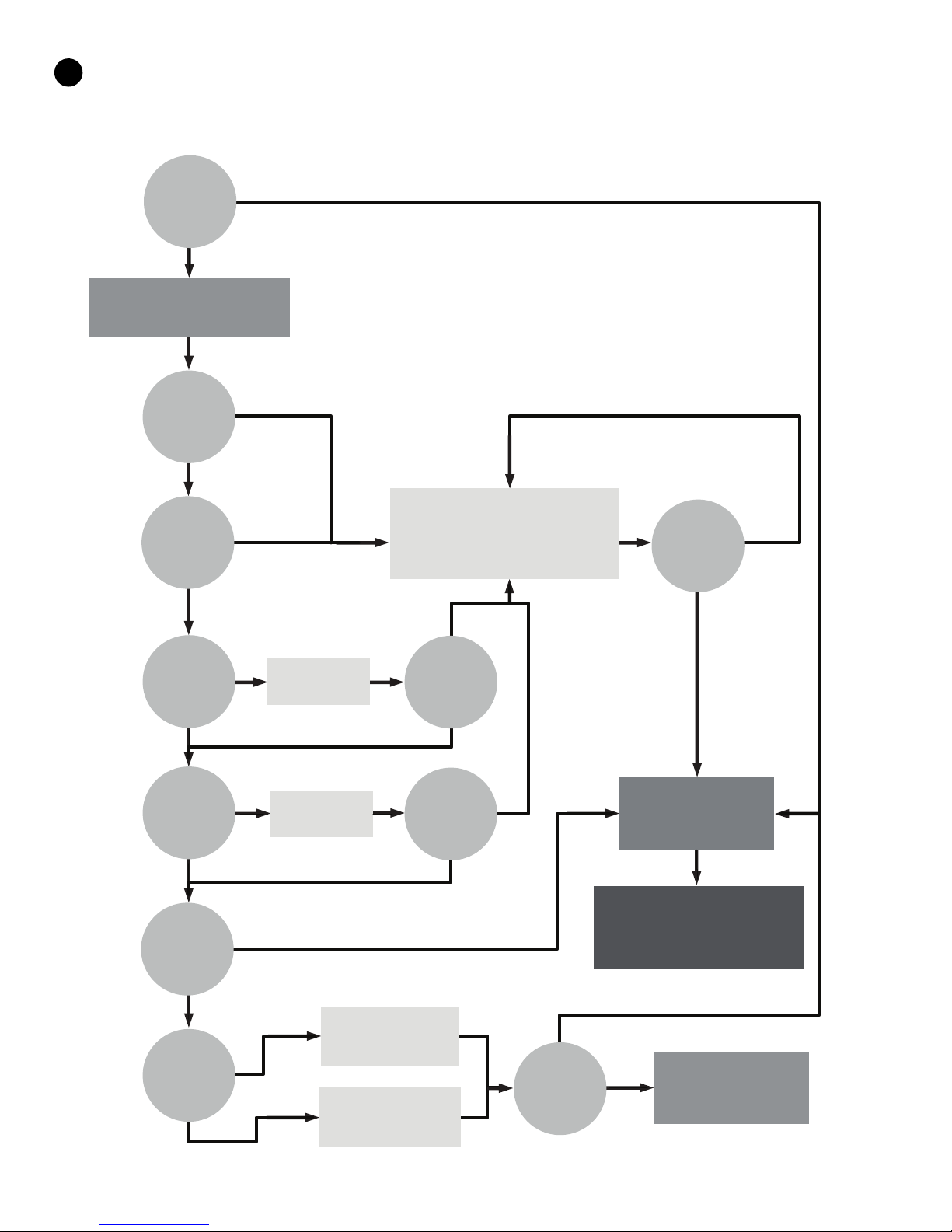
UPM Sequence of Operation (SOO) Flow Chart
YES
YES
YES
YES
YES
YES
YES
YES
YES
YES
YES
NO
NO
NO
NO
NO
NO
NO
NO
NO
NO
NO
Y1=1
V
>
1 8 V AC
HPC = 1
LPC = 1
FRZ
>
TEMP
LIM
CON
>
0
INITIAL
POWER UP T
>
ASC OR
RS SEC
TIME
>
30
SEC
TIME
>
120
SEC
COUNT = 2
Start Timer
Start Timer
CC Output = On
CC Output = Off
Blink Code On Status LED
Report Alarm Fault
Hard Lockout
ALR Output = On/Pulse
Blink Code On Status LED
Soft Lockout
Record Alarm
Start Counter (If Applicable)
Start
Anti Short Cycle
Start
Random Start Up
Lockout Can Be Set To
4 Via Dip Switch
Power/Switchs/Sensor
Status Check
8CA CONSOLE SERIES

970-293 Revised 05-12
9
CA CONSOLE SERIES

970-293 Revised 05-12
10 CA CONSOLE SERIES

970-293 Revised 05-12
11
CA CONSOLE SERIES
970-293 Revised 05-12
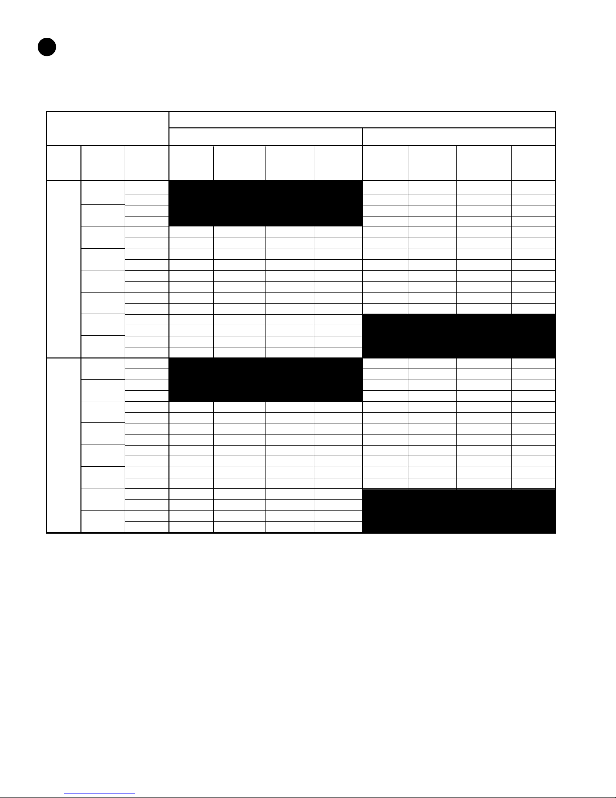
Operating Temperatures & Pressures Consoles
O ERATING DATA R-410A
COOLING HEATING
ENTERING FLUID SUCTION DISCHARGE FLUID AIR SUCTION DSICH FLUID AIR
MODEL FLUID FLOW PRESSURE PRESSURE TEMP TEMP PRESSURE PRESS., TEMP TEMP
TEMP, ˚F GPM PSIG PSIG RISE, ˚F DROP, ˚F PSIG PSIG DROP, ˚F RISE, ˚F
CA009
CA012
30˚
40˚
50˚
60˚
70˚
80˚
90˚
100˚
30˚
40˚
50˚
60˚
70˚
80˚
90˚
100˚
1.5 120-125 295-305 4.3-4.7 12.2-13.4
2 125-130 300-310 3.3-3.7 12.4-13.8
1.5 120-125 300-305 5.2-5.8 14.3-15.8
2 125-130 300-310 4.1-4.5 14.6-16.2
1.5 125-130 285-295 12.8-14.2 18.1-20.0 135-140 305-310 6.2-6.8 16.2-18.0
2 126-131 275-285 10.5-11.6 18.1-20.0 130-135 310-320 4.8-5.3 16.7-18.5
1.5 127-132 295-305 12.6-14.0 17.4-19.2 135-140 315-320 7.1-7.9 18.3-20.3
2 125-130 285-295 9.8-10.8 17.6-19.4 140-145 320-330 5.5-6.1 18.8-20.8
1.5 132-137 315-325 12.4-13.8 16.7-18.5 155-165 325-335 8.2-9.0 20.0-22.2
2 130-135 305-315 9.7-10.7 17.0-18.8 160-170 330-340 6.3-6.9 20.9-23.1
1.5 136-141 345-355 12.4-13.7 16.2-17.9 165-175 335-345 9.0-10.0 22.3-24.7
2 135-140 335-345 9.5-10.5 16.3-18.1 170-175 340-350 7.0-7.8 22.9-25.3
1.5 139-144 370-380 12.2-13.4 15.5-17.1
2 137-142 360-370 9.4-10.4 15.7-17.3
1.5 141-145 415-425 12.1-13.3 14.8-16.4
2 139-144 410-420 9.3-10.3 15.1-16.7
2 110-115 305-315 4.6-5.0 15.3-16.9
3 115-120 305-315 3.8-4.2 15.6-17.2
2 110-115 310-315 5.4-6.0 17.4-19.2
3 115-120 310-315 4.5-4.9 17.8-19.6
2 140-145 290-300 12.5-13.9 20.0-22.2 115-120 315-320 6.3-6.9 19.5-21.5
3 135-140 270-280 10.3-11.3 20.2-22.4 120-125 320-325 5.1-5.7 19.9-21.9
2 142-147 320-320 12.4-13.7 19.4-21.4 125-130 325-330 7.0-7.8 21.5-23.7
3 137-142 300-310 10.2-11.2 19.7-21.7 130-135 330-335 5.8-6.4 21.9-24.2
2 145-150 335-345 12.3-13.5 18.9-20.9 145-150 335-240 7.9-8.7 23.5-25.9
3 143-152 325-335 10.1-11.1 19.1-21.1 150-155 340-350 7.4-8.2 23.9-26.5
2 152-157 360-370 12.2-13.4 18.3-20.3 155-160 345-350 8.7-9.7 25.6-28.2
3 150-155 350-360 10.0-11.0 18.5-20.5 160-165 350-360 7.1-7.9 26.0-28.8
2 154-159 385-395 12.1-13.3 17.8-19.6
3 152-158 375-385 9.9-10.9 18.1-20.0
2 156-160 435-445 12.0-13.2 17.3-19.1
3 154-159 425-435 9.8-10.8 17.5-19.3
12 CA CONSOLE SERIES

970-293 Revised 05-12
Operating Temperatures & Pressures Consoles
This chart shows approximate temperatures and pressures for a unit in good repair.
The values shown are meant as a guide only and should not be used to estimate
system charge. This chart assumes rated air flow and 80º d.b./67º w.b. entering air
temperature in cooling, 70º d.b. entering air temperature in heating. Heating data at
entering fluid temperatures below 50º assumes the use of antifreeze.
FHP MANUFACTURING
601 N.W 65th Court • Ft. Lauderdale, FL 33309
Phone: (954) 776-5471 • Fax: (800) 776 5529
http://www.fhp-mfg.com
As a result of continuing research and development, specifications are subject to change without notice.
O ERATING DATA R-410A
COOLING HEATING
ENTERING FLUID SUCTION DISCHARGE FLUID AIR SUCTION DSICH FLUID AIR
MODEL FLUID FLOW PRESSURE PRESSURE TEMP TEMP PRESSURE PRESS., TEMP TEMP
TEMP, ˚F GPM PSIG PSIG RISE, ˚F DROP, ˚F PSIG PSIG DROP, ˚F RISE, ˚F
CA015
30˚
40˚
50˚
60˚
70˚
80˚
90˚
100˚
3 110-115 280-290 3.6-4.0 13.6-15.0
4 110-115 290-295 2.9-3.2 13.9-15.3
3 115-120 295-300 4.4-4.8 15.8-17.4
4 115-120 300-305 3.4-3.8 16.2-17.9
3 127-132 275-285 12.4-13.8 21.8-24.0 115-120 305-310 5.2-5.8 18.1-20.1
4 125-130 265-275 9.7-10.7 22.0-24.4 120-125 310-315 4.1-4.5 18.5-20.5
3 129-135 310-320 12.2-13.4 20.7-22.9 125-130 315-320 6.1-6.7 20.5-22.7
4 127-132 295-305 9.4-10.4 21.0-23.2 130-135 320-325 4.8-5.3 21.1-23.3
3 135-140 330-340 11.8-13.0 19.8-21.8 145-150 325-330 6.9-7.7 23.0-25.4
4 133-138 320-330 9.1-10.1 20.0-22.2 150-155 330-340 5.4-6.0 23.6-26.0
3 142-147 355-365 11.5-12.7 18.7-20.7 155-16- 335-340 7.8-8.6 25.3-27.9
4 140-145 345-365 8.9-9.9 19.0-21.0 160-165 345-350 6.0-6.6 25.9-28.7
3 144-149 380-390 11.1-12.3 17.7-19.5
4 143-148 370-380 8.6-9.6 18.0-19.8
3 147-152 430-440 10.8-12.0 16.7-18.5
4 145-150 420-430 8.4-9.2 16.9-18.7
13
CA CONSOLE SERIES

970-293 Revised 05-12
UNIT CHECK-OUT
SHEET
Customer Data
Customer Name ______________________________________________ Date _________________________________
Address _____________________________________________________
_____________________________________________________
Phone_______________________________________________________ Unit Number __________________________
Unit Nameplate Data
Unit Make _________________________________________
Model Number_____________________________________ Serial Number_________________________________
Refrigerant Charge (oz) ________
Compressor: RLA _____________ LRA ______________
Blower Motor: FLA (or NPA) ____________ HP_______________
Maximum Fuse Size (Amps) ___________
Minimum Circuit Ampacity (Amps) ______________
Operating Conditions
Cooling Mode Heating Mode
Entering / Leaving Air Temp _______________ /_______________ _______________ /_______________
Entering Air Measured at: _______________________________ _______________________________
Leaving Air Measured at: _______________________________ _______________________________
Entering / Leaving Fluid Temp _______________ /_______________ _______________ /_______________
Compressor Volts / Amps _______________ /_______________ _______________ /_______________
Blower Motor Volts / Amps _______________ /_______________ _______________ /_______________
Fluid Flow (gpm)* _______________________________ _______________________________
Fluid Side Pressure Drop* _______________________________ _______________________________
Suction / Discharge Pressure (psig)* _______________ /_______________ _______________ /_______________
Suction / Discharge Temp* _______________ /_______________ _______________ /_______________
Suction Superheat* _______________________________ _______________________________
Entering TXV / Cap Tube Temp* _______________________________ _______________________________
Liquid Subcooling* _______________________________ _______________________________
* Required for Troubleshooting ONLY
Auxiliary Heat
Unit Make _________________________________________
Model Number _____________________________________ Serial Number ________________________________
Max Fuse Size (Amps) _______________________________
Volts / Amps_____________________ /____________________
Entering Air Temperature ____________________________
Leaving Air Temperature _____________________________
CS-7.2-FO-15.Rev.0
14 CA CONSOLE SERIES
970-293 Revised 05-12
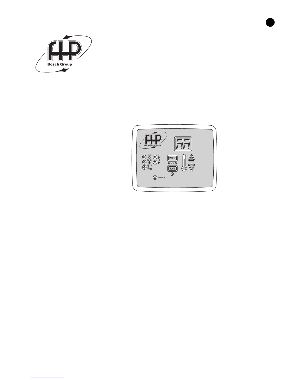
FHP introduces the latest in console solid state control technology. Designed to
enhance the unit operation with more flexibility, accurate control and
operating modes the CUC provides an increased level of comfort in the
conditioned space together with solid state reliability and ease of operation.
The same functions of the proven UPM module are incorporated into the CUC
for unit protection.
CUC controllers are standard on all FHP
series CA/CS console units except for
remote and master/slave options.
• Ta tile tou hpad for
temperature, fan and mode
adjustment.
• Digital display of temperature
in either degrees Fahrenheit or
Celsius.
• LED Display provides
indication for unit operating mode as well as fan speed and fault
indication for high or low pressure lockout.
• Adjustable Temperature Set point from 60° F through 80° F (15.5° C
through 26.7° C ).
• Adjustable Temperature Differential between 1° F and 6° F
(0.6° C and 3.3° C).
• Sele table options
•Manual/Automatic changeover
•Fan speed – High or Low
•Fan operation constant fan or cycling with compressor
• Additional features
•5 minute anti short cycling delay
•Random start
•90 second low pressure bypass timer prevents nuisance lockouts
during cold winter start up
•Intelligent reset allows the unit to automatically restart after 5
minutes if a fault is no longer active
CUC SOLID STATE
CONSOLE UNIT CONTROLLER
15
CA CONSOLE SERIES

970-293 Revised 05-12
601 N.W. 65th C urt, Ft. Lauderdale, FL 33309
Ph ne: 954-776-5471 | Fax: 954-776-5529
www.b schtaxcredit.c m | www.fhp-mfg.c m
Table of contents
Other FHP Heat Pump manuals


Popular Heat Pump manuals by other brands

Gree
Gree Vita GWC09ATCXB-D3DNA3A/I Operation manual

A.O. Smith
A.O. Smith AHPW-25 User's information manual

evoheat
evoheat CS Installation & operation manual

Bryant
Bryant 549J Series installation instructions

Waterstage
Waterstage WO G112LCT Series Installation and operating manual

Trane
Trane 2MCC05-C installation manual


Carrier
Carrier bryant 607E K Series installation instructions

CHAFFOTEAUX
CHAFFOTEAUX ARIANEXT COMPACT Installation and servicing instructions

Lennox
Lennox LHT/LDT024 installation instructions

Nibe
Nibe VVM 500 Installer manual

auer
auer HTi70 6 Installation and user manual

Daikin
Daikin Altherma 3 H HT F Series Operation manual