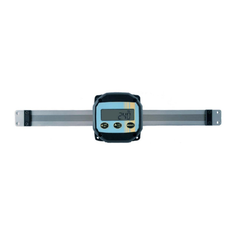
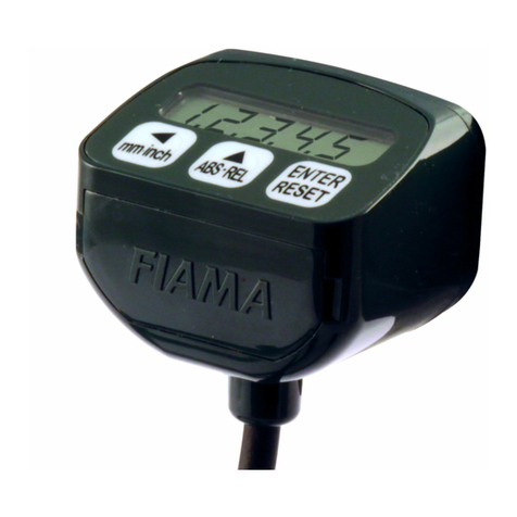
FIAMA F1X5 SSI Series User manual

Display unit with microprocessor F1X5_SSI
Date:13/01/16 F1X_SSI_ing.doc Pag. 1/1
USE AND MAINTENANCE MANUAL
MICROPROCESSOR-BASED DISPLAY UNIT WITH
SSI F1X5_SSI INPUT

Display unit with microprocessor F1X5_SSI
Date:13/01/16 F1X_SSI_ing.doc Pag. 2/2
Purpose of the manual
This manual has been created by the manufacturer to provide all the necessary information to those who,
relative to the instrument, are authorised to carry out safely installation , maintenance, dismantling and
disposal tasks. All necessary information for buyers and designers is reported in the “sales catalogue”. In
addition to complying with the correct technical construction rules, the information must be read attentively
and rigorously applied.
Non compliance with the stated rules can cause health risks, risks to personal safety and cause economic
damage. This information manual, originally created by the manufacturer in the Italian language, is also
available in other languages to satisfy legislative and/or commercial requirements. The documentation must
remain in the possession of the person responsible for the proposed task, in a suitable place to conserve it in
the best condition, where it is easily accessible for consultation. In the case that it is lost or deteriorates,
request a substitute directly to the manufacturer, quoting the code of the present manual. The manual reflects
the technological status at the time the product is introduced on the market. The manufacturer however,
reserves the right to make modifications, additions or improvements to the same manual without the need to
consider the current version as unsuitable.
Identification of equipment
The identification plate is applied to the instrument. To determine the meaning of the instrument identification
code, refer to the sales catalogue.
Environmental Conditions
Ambient temperature range: min. 0°C, max.+ 50°C. It is forbidden to use the instrument, if not explicitly
permitted for the purpose, in potentially explosive atmospheres or where the use of anti-explosive
components is required.
Storage
Below are some recommendations to which attention should be paid in the storage of the instrument. Avoid
excessively humid environments and exposure to the elements (do not store outside). Avoid the instrument
direct contact with the floor. Place the instrument in its original packaging.
Declaration of conformity and CE marking
The instrument complies with the following Community Directives:
2014/30/EU Electromagnetic compatibility, 2014/35/EU Low voltage, 2011/65/EU RoHS.
Maintenance
The equipment does not require particular maintenance interventions except cleaning, which must only be
carried out exclusively with a soft, damp cloth with ethylic alcohol or water. Do not use solvents derived from
hydrocarbons (trichloroethylene, gasoline, diluents etc.). The use of these products will irreversibly
compromise the functioning of the instrument. Repairs must be carried out exclusively at a FIAMA technical
assistance centre.
Calibrations and checks
It is advisable to check calibration of the instrument periodically, about every working year. To carry out
calibrations, refer to the calibration procedure described in this manual.
When assistance is required
For any technical assistance required, refer directly to the sales network of the manufacturer, stating the
figures indicated on the identification plate, the approximate number of hours of use and the type of fault
detected.
Responsibilities of the manufacturer
The manufacturer is not responsible in case of:
• use of the instrument which does not comply with national safety and accident-prevention laws;
• incorrect installation, lack or incorrect observation of the instructions stated in this manual;
• Electricity supply faults;
• Modifications or tampering;
• Operations being conducted by unauthorised or unqualified personnel.
The safety of the instrument also depends on the scrupulous compliance to the regulations stated in this
manual, and in particular it is necessary: always operate within the operating limits of the instrument and
always carry out a careful ordinary maintenance.
• Assign to the inspection and maintenance phases operators trained to carry out this task.
• The preset configurations in this manual are the only ones permitted.
• Do not try to use the instrument in any way other than that stated in the instructions provided.

Display unit with microprocessor F1X5_SSI
Date:13/01/16 F1X_SSI_ing.doc Pag. 3/3
• The stated instructions in this manual do not substitute, but complement the obligations of the legislation in
force regarding safety regulations.
Description
The F1X5_SS instrument is six-digit display unit (reading scale –99999 , +999999) with an input from
transducers that use the SSI interface (encoder, optical lines, position transducers, pressure transducers,
etc.). Through four keys placed on the front panel, it is possible to set up all parameters of the instrument, in
particular the SSI protocol (gray or binary), the bit number (selection from 4 to 24), the scale factor, the
method for the reset/preset of the dimension, etc. The display unit can be provided in versions with two relay
outputs with programmable thresholds and an output RS232/RS485 for communication with remote units
(PLC) in modbus protocol.
The instrument stores the data when the machine is off through non-volatile EEPROM memory.
The display unit is housed in a 48x96 panel case under the DIN 43700 regulations.
Front view
RESET
ENTER
PGM
set1 set2
Display
Tasti
Rear view
12345678
123456
M1
Morsettiera
alimentazione
M2
Morsettiera
ingressi
910
Installation
Before installing, connecting or using the instrument read the following instructions:
a) Connect the instrument scrupulously following the manual instructions.
b) Always make the connections using types of cable appropriate for the power and current limits indicated in
the technical data.
c) The instrument is NOT equipped with an On/Off switch, therefore it turns on immediately when connected
to the power supply; for safety reasons the equipment permanently connected to the electricity supply
requires: a two-phase selector switch marked with the appropriate symbol; this will be positioned in the
vicinity of the instrument to be easily accessible to the operator; a single switch can control numerous
instruments.
d) If the instrument is connected to NON-insulated electrical equipment (e.g. thermocouples), the earth
connection must be carried out with a specific lead to prevent this taking place directly through the very
structure of the machine.
e) If the instrument is used in applications with risks of damage to people, machines or materials, it is
absolutely necessary that it is combined with auxiliary alarm systems. It is advisable to ensure the possibility
of verifying the intervention of the alarms also during regular functioning.
f) It is the responsibility of the user to verify, before use, the correct selection of the instruments parameters,
to avoid damages to people or property.
g) The instrument will NOT work in environments with a dangerous atmosphere (inflammable or explosive); it
can be connected to elements which operate in such atmosphere only through appropriate and suitable types
of interface, conforming to the local regulations in force.

Display unit with microprocessor F1X5_SSI
Date:13/01/16 F1X_SSI_ing.doc Pag. 4/4
h) The instrument contains components sensitive to electrostatic charge, therefore the handling of the
electronic cards in it must be carried out with the appropriate devices, with the aim of avoiding permanent
damage to the very components.
Power supply
a) Before connecting the instrument verify that the power voltage is within the permitted limits indicated on the
plate.
b) Carry out electrical connections with the instrument disconnected.
c) For the instruments and sensors supply, beforehand create a supply line separated from the power line: if
necessary use an isolating transformer.
d) The supply line must provide a sectioning device with fuses upstream the instruments and must not be
used to control relays, contactors etc.
e) If the network voltage is seriously disturbed (switching of power groups, motors, inverters, welders etc.)
use the appropriate filters.
f) If an earth connection is required, make sure that the equipment is provided with a good earth installation:
voltage between neutral and earth <1V and resistance < 6 Ohm.
Connection of inputs and outputs
a) Physically separate the input cables from the supply cables, the output cables and from the power
connections; use shielded twisted pair cables, with display unit connected to ground in one point only .
b) Connect the setting and alarm outputs (contactors, solenoid valves, motors, electric fans, etc.) by
assembling RC groups (resistance and capacitor in series) parallel to inductive loads working in AC mode.
Assembly of the instrument
For a correct installation of the instrument, follow the procedure outlined below:
1. Insert the instrument in the specific cut-out.
2. Screw the screw onto the fixing block.
3. Hook the block to the instrument by means of the gains
4. Block the instrument by screwing the screws of the two blocks.
5. After that, make the electrical connections.
To assemble several instruments side-by-side, make sure axle bases are correct, as shown in the drawing.
Dimensions A and B can be read in the overall dimensions indicated in the manual.

Display unit with microprocessor F1X5_SSI
Date:13/01/16 F1X_SSI_ing.doc Pag. 5/5
PROGRAMMING
The keys used for programming are the following:
PGM To start programming
To increase the digit undergoing modification,
To select the constant to be modified
To move from one digit to the next one,
To exit the constant setting mode
RESET/ENTER To confirm the entered values
Push PGM To enter the programming phase, the wording “000” will be displayed with the first
digit to the right blinking: this is the password request; enter the number 273 as
outlined below:
push To increase the value of the blinking digit,
push To select the blinking digit,
After setting the value 273, confirm by means of RESET/ENTER and the wording %%.
%%.%%.
%%. will be displayed for
some seconds, followed by a 3-digit number.
N.B.: in case a wrong password is entered, the instrument exits the programming phase.
push RESET/ENTER And modify the value of the constant by means of keys , or
push To move to other constants, or
push twice in a row to exit the programming mode.
The constants to be set, which once in the programming phase can be scrolled by means of the key , are
the following:
%%.
%%.%%.
%%. address device for serial comunication (not used in this version),
# %
# %# %
# % Baude Rate for serial comunication (not used in this version),
+0/
+0/+0/
+0/ Gray/Binary data format
reset mode,
./
././
./ Preset dimension,
/
//
/ SSI input filter,
#)/
#)/#)/
#)/ number of bits of the SSI interface ,
)+
)+)+
)+ data format with or without sign,
/
//
/ Dimension offset ,
+%
+%+%
+% Position of the decimal point,
0/
0/0/
0/ Dimension multiplication factor,
%
% %
% Dimension division factor
Meaning of constants
%%.
%%.%%.
%%. Address device for serial comunication
Not used in this version.
#0%
#0%#0%
#0% Baud rate for serial comunication
Not used in this version.
+0/
+0/+0/
+0/ Gray/Binary data format

Display unit with microprocessor F1X5_SSI
Date:13/01/16 F1X_SSI_ing.doc Pag. 6/6
It defines the format of data of the SSI interface: if 0, the format is binary; if 1 the format is Gray. This
parameter shall be set in line with what is requested by the transducer connected to the display unit.
Reset mode
Setting of the reset mode allows for the selection of the instrument behaviour when the RESET/ENTER key is
pushed or after activation of the RESET input.
On the basis of the following table, select the chosen reset mode:
Action of the RESET/ENTER key
or RESET INPUT
0 Key disabled
1 Reset
2Preset
3 Incremental/absolute reading function (*)
4 Delayed Reset (push for 1 sec approx.)
5 Delayed Preset (push for 1 sec approx.)
(*) the absolute/incremental reading function enables you to reset the dimension in one point, make a change
and then restore display of the absolute dimension.
Example: if the current position is 100 (absolute dimension), by pushing RESET/ENTER or by activating the
RESET input, you move to the relative dimension, the dimension on the display is zero set and the first digit to
the right blinks to indicate the relative reading mode. By a change of 50, 50 will appear on the display; by
pushing RESET/ENTER or by activating the RESET input, the display will show the absolute dimension that will
be 150 (= 100 + 50).
By turning off the instrument with relative dimension displayed, when switching on the instrument, the
absolute dimension is displayed and the relative dimension is lost.
./
././
./ Preset dimension
The instrument allows for the setting of the value that will be displayed after pushing the RESET/ENTER key, in
line with what is indicated in the table above M.Azz. “Reset mode ”.
Allowed values range between –999999 and 999999.
/
//
/ SSI input filter
By setting 1, the noise-proof filter is activated (if this function is supported by the transducer). For example,
with the transducer for absolute magnetic band MAT, the measure of the dimension is made with a double
reading Burst, leaving a smaller interval of tm (16µs) between the first and the second Burst, so that the
dimension is not updated between the two readings. Consequently, if the two dimensions were different, this
would mean the reading has been altered by the noise and shall hence be repeated .
By setting 0 (default value) this function is disabled.

Display unit with microprocessor F1X5_SSI
Date:13/01/16 F1X_SSI_ing.doc Pag. 7/7
#)/
#)/#)/
#)/ Number of bits of the SSI interface
Number of bits of the SSI protocol to be set in line with the value requested by the transducer connected to
the F1X5_SSI display unit. Such value can range between 4 and 24.
Default value: 24. Value for the MAT transducer: 24.
)+
)+)+
)+ SSI data item with or without sign
It defines the display mode of the data provided by the SSI transducer. Example: with )+
)+)+
)+= 0, in a 4-bit
communication in binary format, dimension 1111 is displayed as 15 , otherwise, if )+
)+)+
)+= 1, –1 is displayed,
being negative numbers represented in two’s complement.
N.B: if the bit number is 24, all the negative dimensions are displayed with negative sign regardless of the
value of
)+
)+)+
)+ Value for the MAT transducer: 0
/
//
/ Displayed dimension offset
By means of this constant it is possible to add or subtract a value from the dimension shown on the display.
By setting a positive value, this value is subtracted from the displayed dimension. By setting a negative
value, this value is added to the displayed dimension.
+%
+%+%
+% Position of the decimal point
This constant indicates the position of the decimal point; set 0 for no decimal, 1 for 1 decimal, etc… Allowed
values: 0 to 4.
0/
0/0/
0/ Dimension multiplication factor
The display unit can modify the value read by the transducer by multiplying it by 0/
0/0/
0/ and dividing it by
%
% %
% . By setting these two constants properly, the chosen value can be shown on the display. The range of
allowed values is 1 ÷999999. Default value 1.
%
% %
% Dimension division factor
See above.
Overall dimensions

Display unit with microprocessor F1X5_SSI
Date:13/01/16 F1X_SSI_ing.doc Pag. 8/8
Connections diagram
1
2
3
4
5
6
7
8
9
10
230Vac
115Vac 0
24Vac 0
15-30Vdc GND
M1 M2
F1X522SSI
F1X532SSI
0F1X512SSI
1
2
3
4
5
6
POWER SUPPLY
TERMINAL BOARD
F1X502SSI
MORSETTIERA
SSI INPUT
TERMINAL BOARD
SSI CLOCK --
SSI CLOCK +
SSI DATA +
SSI DATA --
SSI GND
RESET
CONNECTION FOR
MAT TRANSDUCER
ORANGE
YELLOW
WITHE
PURPLE
GREEN
NB: connect BROWN
to +24Vdc
NOT CONNECTED
Technical features
Power supply 115Vac, 230Vac, 24Vac, 24Vdc ±10%
Line frequency 50/60 Hz
Absorbed power 3VA
Display 6 digits -99999,+999999
Communication protocol SSI (standard RS422)
Number of bits From 4 to 24 (settable)
Data format Gray / binary
Serial port (option) RS232, RS485
Two relay outputs (option) 120Vac, 0,5A; 24Vdc, 1A
Working temperature 0-50°C
Relative humidity 10-90%
Self-extinguishable shock-proof case DIN 43700
(Front) protection of the case IP54
Dimensions (HxLxP) (with terminal board) 48x96x100 mm
Panel Cut-out 45x92 mm
Electromagnetic compatibility 2014/30/EU
Low voltage 2014/35/EU
RoHS 2011/65/EU
Manufacturer
Every communication to the manufacturer shall be addressed to:
FIAMA s.r.l., Via G. Di Vittorio, 5/A - 43016 San Pancrazio (Parma) - Italy
Phone (+39) 0521.672.341 - Fax. (+39) 0521.672.537 - e.mail: info@fiama.it - www.fiama.it
FIAMA srl will not be held responsible for damage to people or property resulting from tampering
with and misuse or use non-complying with the characteristics of the instrument.
This manual suits for next models
4
Table of contents
Other FIAMA Monitor manuals
