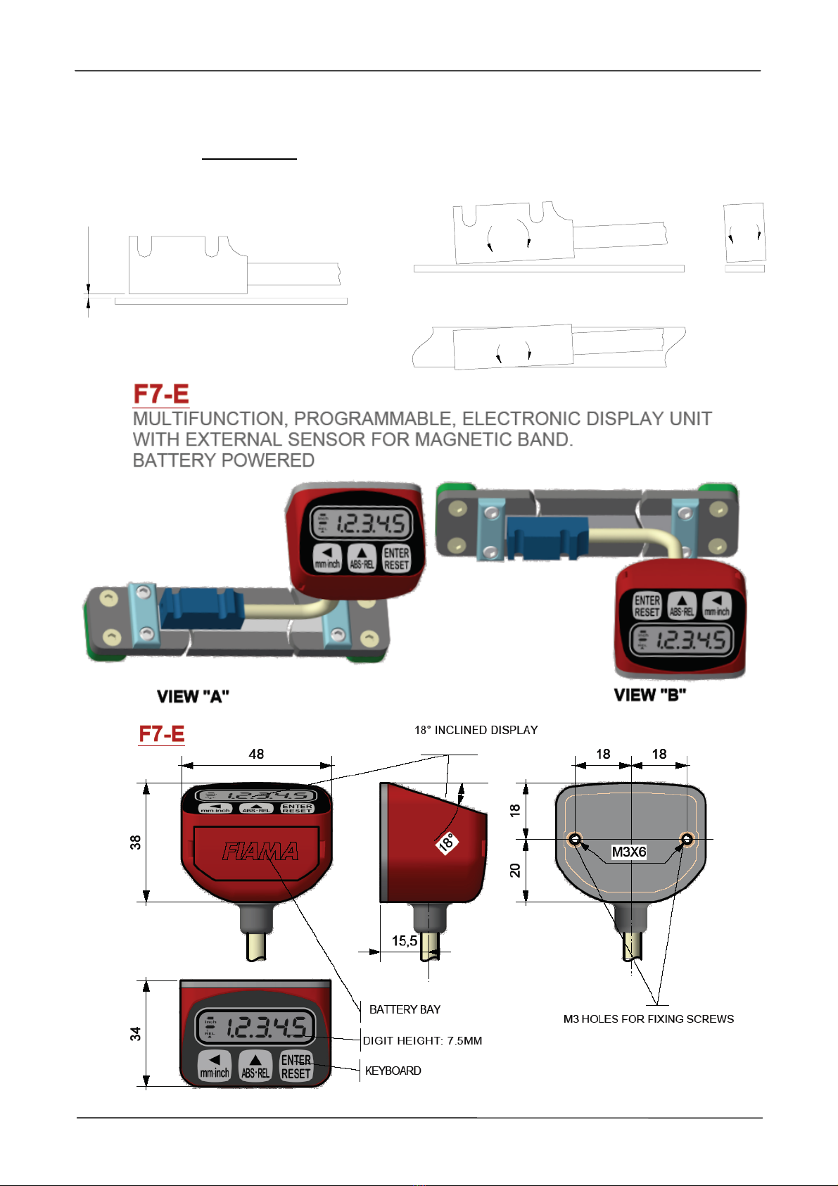
Display for magnetic band F7
Data: 13/01/16 F7_ing.doc pag 5/12
pressing 2 times ENTER/RESET it is possible to set the nominal value for tool 0 (for example the
radius of cutter 0), which is then confirmed by pressing ENTER/RESET.
Now 3U6
3U63U6
3U6 will appear which is the nominal value for tool 1 (for example the radius of cutter 1): set
the correct value and confirm with ENTER/RESET.
Finally 3U6
3U63U6
3U6 will appear which is the nominal value for tool 2 (for example the radius of cutter 2):
set the correct value and confirm with ENTER/RESET.
In practice 3U6
3U63U6
3U6,3U6
3U63U6
3U6, and 3U6
3U63U6
3U6 are the nominal values associated to the three different tools
which are used.
As a special case, if 3U6
3U63U6
3U6 is set to zero, 3U6
3U63U6
3U6 and 3U6
3U63U6
3U6 are the values to display in origin 1 and in
origin 2 respectively.
ABS/REL function: Enables passing from an absolute to relative value; after pressing , the
displayed value is temporarily set to zero to measure a relative motion of the transducer. On the
display the REL icon indicates that the current display is relative to the reference point that has just
been created. Pressing again causes the absolute value to be displayed and the ABS icon will
appear.
mm/inch conversion: Pressing converts the measurement from millimeters to inches and
back. When in inch mode, the INCH icon will appear and the displayed value will have an additional
decimal place. When the parameter QG(&
QG(&QG(&
QG(&=4 the mm/inch conversion is not available.
Offset: This parameter is added to or subtracted from the displayed value to correct it in case, for
example, of a tool change or to compensate tool wear. After setting a positive offset value, the
displayed value will be the measured value plus the offset value. After setting a negative offset
value, the displayed value will be the measured value minus the offset value.
Fast Offset: After pressing ENTER/RESET,2))6W
2))6W2))6W
2))6W appears and by pressing two times ENTER/RESET
it is possible to set directly the value to be displayed (use buttons and confirm with
ENTER/RESET). This function is useful if it is necessary to correct often the displayed value.
%.
%.%.
%.
Count direction
Set out the count direction of the display, range allowed 0 or 1.
Adjustment of displayed value
After the installation of instrument on the machine and setting of all parameters, in order to visualize
on the display the correct value it is necessary to carry out the reset or preset.
Position the shaft in a point in which the correct measure that has to be visualized is known exactly
(for example the stroke end point) or measure the position in that point of the shaft. Program
parameter W$6W,
W$6W,W$6W,
W$6W, with value 3 in the first digit on the right and exit programming.
Now press ENTER/RESET and 3U6W
3U6W3U6W
3U6Wwill appear, press again 2 times ENTER/RESET and set the correct
value to display, then confirm with ENTER/RESET. The display will now show the desired value.
If the required value is zero, instead of the preset function it is possible to use the reset function by
setting 1 in the first digit on the right in the W$6W,
W$6W,W$6W,
W$6W,parameter so that pressing ENTER/RESET will bring
the displayed value to zero.
Now that the instrument is adjusted, it is necessary to insert the desired W$6W,
W$6W,W$6W,
W$6W,parameter to avoid
accidental reset/preset of the displayed value.
Battery replacement
The instrument is supplied with a ½AA 3,6V lithium battery, which assures a typical functioning of
approximately 4 years.
When the battery runs down, an icon appears on the display.
To enter into the battery-holder it is necessary to remove the front cover by carefully inserting a flat
screwdriver on the sides. After taking off the cover, pull the battery out and substitute it with a new
one, paying attention to the polarity: the positive pole must face the side of the ENTER/RESET
button. The instrument is protected against inversion of polarity and wrong insertion, and in this
case will not switch on.