FIBARO FGWPx-102 User manual

OPERATING
MANUAL
FIBARO WALL PLUG
FGWPx-102
CONTENTS
#1: Description and features 4
#2: Basic activation 5
#3: Adding/removing the device 6
#4: Operating the device 7
#5: Power and energy consumption 9
#6: Association 10
#7: Z-Wave range test 11
#8: Advanced parameters 12
#9: Specications 19
#10: Guarantee 20
ENG
v2.0


3
Important safety information
Read this manual before attempting to install the device!
Failure to observe recommendations included in this manual
may be dangerous or cause a violation of the law. The manufacturer,
Fibar Group S.A. will not be held responsible for any loss or damage
resulting from not following the instructions of operating manual.
!
General information about
the FIBARO System
FIBARO is a wireless smart home automation system, based on the
Z-Wave protocol. All of available devices can be controlled through
a computer (PC or Mac), smartphone or tablet. Devices are not only
receivers, but can also repeat the signal, increasing the Z-Wave
network’s range. It gives advantage over traditional wireless systems
that require direct link between transmitter and receiver, as a result the
construction of the building could aect network’s range negatively.
Every FIBARO network has its unique identication number (home
ID). Multiple independent networks can exist in the building without
interfering. Transmission security of FIBARO System is comparable to
wired systems.
Z-Wave technology is the leading solution in smart home automation.
There is a wide range of Z-Wave devices that are mutually
compatible, independently of manufacturer. It gives the system the
ability to evolve and expand over time. For more information visit:
www.baro.com.

4
DESCRIPTION AND FEATURES
Main features of FIBARO Wall Plug:
• Compatible with any Z-Wave or Z-Wave+ Controller.
• Supports protected mode (Z-Wave network security mode) with
AES-128 encryption.
• Extremely easy installation - simply plug the device into the mains
socket.
• Works as a Z-Wave signal repeater.
• Active power and energy consumption metering.
• Current value of the load and operating mode are indicated by the
multi-colour LED ring.
FIBARO Wall Plug is a universal, Z-Wave Plus compatible, remotely
controlled outlet adapter. This device may be applied wherever you
want to control electrical devices with up to 2500W load.
The Wall Plug is equipped with a power and energy metering
function. It uses a LED ring to visualize the current load with colour
changing illumination and operating mode. This is the smallest and
most attractive device of this type available in the world.
The Wall Plug may be operated using the B-button located on its
casing or via any Z-Wave compatible controller.
#1: Description and features
FIBARO Wall Plug is a fully
compatible Z-Wave PLUS device.
NOTE
This device may be
used with all devices
certied with the
Z-Wave Plus certicate
and is compatible
with such devices
produced by other
manufacturers.
i
NOTE
FIBARO Wall Plug is
a Security Enabled
Z-Wave Plus product
and a Security Ena-
bled Z-Wave Control-
ler must be used in or-
der to fully utilize the
product.
i

5
BASIC ACTIVATION
#2: Basic activation
1. Plug the device into a socket nearby the main Z-Wave controller.
2. Set the main Z-Wave controller in add mode.
3. Quickly, triple click the B-button located on the casing.
4. Wait for the device to be added to the system.
5. Successful adding will be conrmed by the controller.
6. Plug a device you want to control into the Wall Plug.
7. Test the device by turning it on and o using the B-Button.
NOTE
When powered, the
device will indicate
Z-Wave status with
colour of LED ring:
• Green - the device is
already added to the
Z-Wave network.
• Red - the device is
not added to any
Z-Wave network.
i

6
ADDING/REMOVING THE DEVICE
#3: Adding/removing the device
Adding (Inclusion) - Z-Wave device learning mode, allowing to add
the device to existing Z-Wave network.
To add the device to the Z-Wave network:
1. Plug the device into a socket nearby the main Z-Wave controller.
2. The LED ring will glow red signalling not being added (remove the
device otherwise).
3. Set the main controller in (security/non-security) add mode (see
the controller’s manual).
4. Quickly, triple click the B-button located on the casing.
5. Wait for the adding process to end.
6. Successful adding will be conrmed by the Z-Wave controller’s
message.
Removing (Exclusion) - Z-Wave device learning mode, allowing to
remove the device from existing Z-Wave network.
To remove the device from the Z-Wave network:
1. Plug the device into a socket nearby the main Z-Wave controller.
2. The LED ring will glow green signalling being added (removing is
not necessary otherwise).
3. Set the main controller into remove mode (see the controller’s
manual).
4. Quickly, triple click the B-button located on the casing.
5. Wait for the removing process to end.
6. Successful removing will be conrmed by the Z-Wave controller’s
message.
NOTE
Adding in security
mode must be per-
formed up to 2 meters
from the controller.
i
NOTE
Removing Wall Plug
from the Z-Wave net-
work restores all the
default parameters of
the device.
i
NOTE
In case the device is
not added, please
reset the device and
repeat the adding
procedure.
i

7
OPERATING THE DEVICE
#4: Operating the device
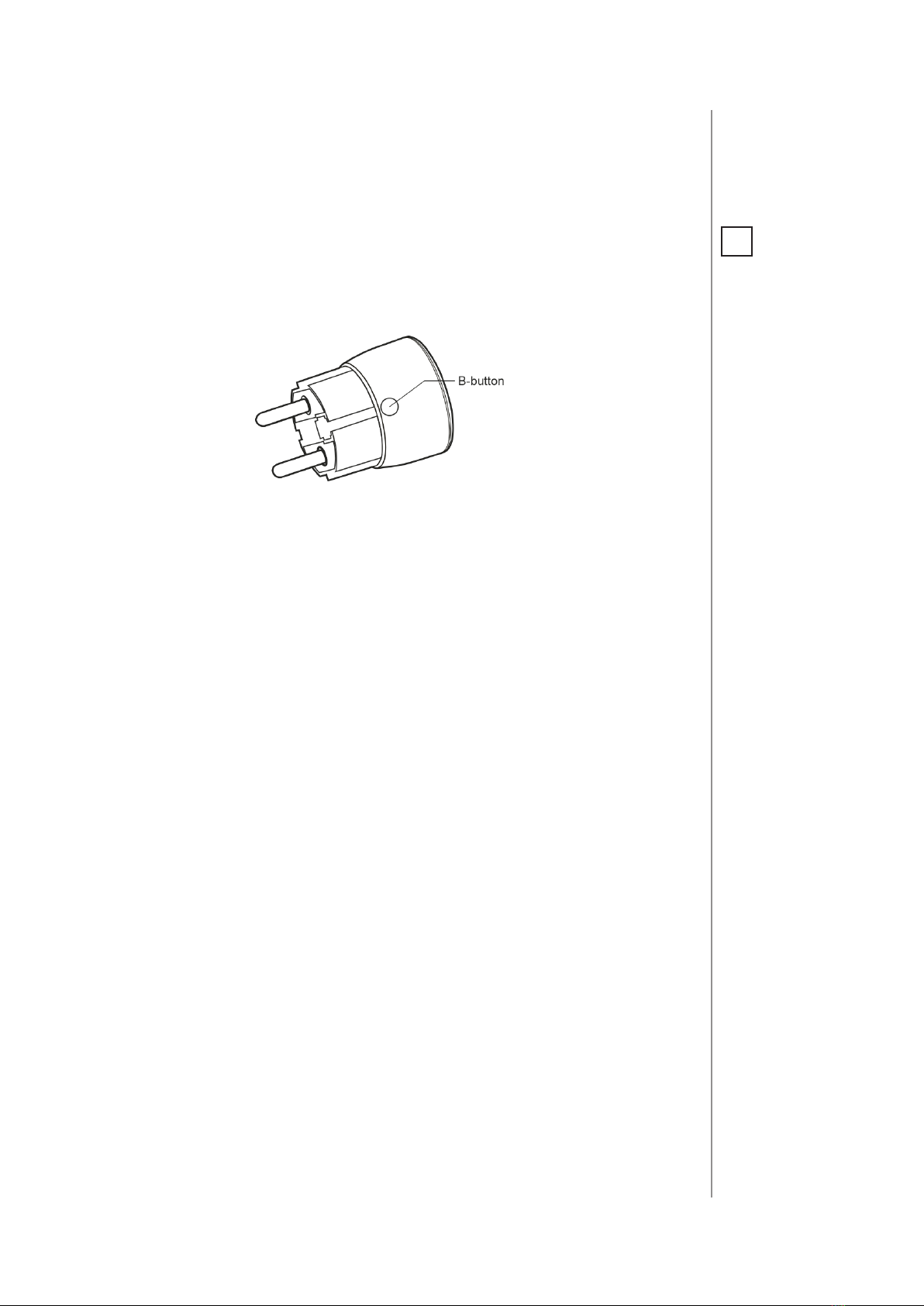
Controlling the Wall Plug using the B-button:
Wall Plug is equipped with a B-button, which allows to use the menu
mode and additionally perform the following actions:
1x click: turn controlled device ON/OFF, conrm selected menu op-
tion (if menu is active)
3x click: add/remove the device to/from a Z-Wave network
Holding: enter/navigate through menu
Visual indications:
FIBARO Wall Plug is equipped with a LED ring, signalling sensor’s op-
erating modes and current active power consumption. In addition
the visual indicator may inform of the Z-Wave network range.
Visual indicator ring signalling modes:
1. By default, when the device is turned ON, the colour will vary de-
pending on the current active power consumption.
2. Once inserted to mains socket the device signals Z-Wave network
inclusion status with blink (green - added, red - not added).
3. Menu position is signalled with assigned illumination colour.
4. Ongoing software update is signalled with cyan blinking.
5. Range of the Z-Wave network with colour depending on type of
communication or the lack of it (only in range tester mode).
Disabling visual indicator:
Visual indication ring may be turned o for status signalling (turned
ON/OFF, power consumption). That means each status change will
be signalled by a short white blink of the ring. Disabling it will not
change operation of the device. To disable the LED ring:
1. Insert the Wall Plug in a socket.
2. Press and hold the B-button for about 3 seconds.
3. Release the B-button after LED ring starts pulsing white.
To restore visual indications perform above procedure again.
NOTE
Disabling the LED ring
indications will also
aect alarm signaliza-
tion.
i

8
OPERATING THE DEVICE
Resetting the Wall Plug:
Reset procedure allows to restore the device back to its factory set-
tings, which means all information about the Z-Wave controller and
user conguration will be deleted.
1. Make sure the device is powered.
2. Press and hold the B-button.
3. Wait for the LED ring to glow yellow (4th menu position).
4. Release the B-button.
5. Click the B-button once to conrm selection.
6. After few seconds the device will restart with factory settings,
which is signalled with the red ring colour.
NOTE
Resetting the device is
not the recommend-
ed way of removing
the device from the
Z-Wave network. Use
reset procedure only
if the primary con-
troller is missing or
inoperable. Certain
device removal can be
achieved by the pro-
cedure of removing
described in “Adding/
removing the device”
on page 6.
i
Controlling the Wall Plug with FIBARO Home Center controller:
FIBARO Wall Plug after successful adding is represented in the
Home Center interface with a single icon. It allows to turn on and o
the device and displays current active power and cumulative energy
consumption.
Menu allows to perform Z-Wave network actions. In order to use the
menu:
1. Press and hold the B-button.
2. Wait for the device to indicate desired position with a colour:
• GREEN - erase energy consumption memory
• VIOLET - Z-Wave network’s range test
• YELLOW - device reset
3. Release the B-button.
4. Click the B-button to conrm selection.
NOTE
Menu is preceded by
two white ashes of
the LED ring 6 seconds
after the B-button is
pressed.
i

9
POWER AND ENERGY CONSUMPTION
#5: Power and energy
consumption
Wall Plug allows to monitor the active power and energy consump-
tion. Data is sent to the main Z-Wave controller, e.g. Home Center.
Measuring is carried out by the most advanced micro-controller tech-
nology, assuring maximum accuracy and precision.
Electric active power - power that energy receiver is changing into a
work or a heat. The unit of active power is Watt [W].
Electric energy - energy consumed by a device through a time
period. Consumers of electricity in households are billed by sup-
pliers on the basis of active power used in given unit of time. Most
commonly measured in kilowatt-hour [kWh]. One kilowatt-hour is
equal to one kilowatt of power consumed over period of one hour,
1kWh = 1000Wh.
Resetting consumption memory:
Wall Plug allows to erase stored consumption data (turning it o/on
or removing it from the socket will not erase consumption):
1. Make sure the device is powered.
2. Press and hold the B-button.
3. Release the B-button when the LED ring glows green (2nd menu
position).
4. Press the B-button briey.

10
ASSOCIATION
#6: Association
FIBARO Wall Plug provides the association of three groups:
1st Association Group – “Lifeline” reports the device status and al-
lows for assigning single device only (main controller by default).
2nd Association Group – “On/O (button)” devices in this group
will be switched on or o when relay status is changed using the
B-button (done via BASIC SET command frames).
3rd Association Group – “On/O (power)” devices in this group
will be switched on or o depending on the current load (done via
BASIC SET command frames).
To add an association (using the FIBARO Home Center controller):
1. Go to device options by clicking the icon:
2. Select the„Advanced” tab.
3. Specify to which group and what devices are to be associated.
4. Wait for the conguration process to end. Sending relevant infor-
mation to devices added to associated groups may take even a
few minutes.
NOTE
Association ensures
direct transfer of
control commands
between devices, is
performed without
participation of the
main controller and
requires associated
device to be in the di-
rect range.
i
FIBARO Wall Plug in 2nd and 3rd group allows to control
up to 10 regular or multichannel devices per an association group, with
the exception of “LifeLine” that is reserved solely for the controller and
hence only 1 node can be assigned.
It is not recommended to associate more than 10 devices in general,
as the response time to control commands depends on the number
of associated devices. In extreme cases, system response may be de-
layed.
Association (linking devices) - direct control of other devices within
the Z-Wave system network e.g. Dimmer, Relay Switch, Roller Shutter
or scene (may be controlled only through a Z-Wave controller).
NOTE
2nd association group
commands are sent
only in case of manual
operation through the
B-button.
3rd association group
commands are sent
automatically, de-
pending on parame-
ters 21, 22, 23 and 24.
i

11
ZWAVE RANGE TEST
#7: Z-Wave range test
FIBARO Wall Plug has a built in Z-Wave network main controller’s
range tester.
Follow the below instructions to test the main controller’s range:
1. Press and hold the B-button.
2. Wait for the LED ring to glow violet (3rd menu position).
3. Release the B-button.
4. Click the B-button once to conrm selection.
5. Visual indicator will indicate the Z-Wave network’s range (range
signalling modes described below).
6. To exit Z-Wave range test, press the B-button briey.
Z-Wave range tester signalling modes:
Visual indicator pulsing green - Wall Plug attempts to establish a
direct communication with the main controller. If a direct commu-
nication attempt fails, the device will try to establish a routed com-
munication, through other modules, which will be signalled by visual
indicator pulsing yellow.
Visual indicator glowing green - Wall Plug communicates with the
main controller directly.
Visual indicator pulsing yellow - Wall Plug tries to establish a rout-
ed communication with the main controller through other modules
(repeaters).
Visual indicator glowing yellow - Wall Plug communicates with the
main controller through the other modules. After 2 seconds the de-
vice will retry to establish a direct communication with the main con-
troller, which will be signalled with visual indicator pulsing green.
Visual indicator pulsing violet - Wall Plug does communicate at the
maximum distance of the Z-Wave network. If connection proves suc-
cessful it will be conrmed with a yellow glow. It’s not recommended
to use the device at the range limit.
Visual indicator glowing red - Wall Plug is not able to connect to the
main controller directly or through another Z-Wave network device
(repeater).
CAUTION
To make Z-Wave range
test possible, the de-
vice must be added
to the Z-Wave control-
ler. Testing may stress
the network, so it is
recommended to per-
form the test only in
special cases.
!
NOTE
Communication mode
of the Wall Plug may
switch between direct
and one using rout-
ing, especially if the
device is on the limit
of the direct range.
i

12
ADVANCED PARAMETERS
#8: Advanced parameters
FIBARO Wall Plug allows to customize its operation to user’s needs.
The settings are available in the FIBARO interface as simple options
that may be chosen by selecting the appropriate box.
In order to congure FIBARO Wall Plug (using the FIBARO Home
Center controller):
1. Go to the device options by clicking the icon:
2. Select the„Advanced” tab.
GROUP 0. WALL PLUG GENERAL SETTINGS
1. Always On function
Once activated, Wall Plug will keep the connected device constantly
ON, will stop reacting to alarm frames or pushing the B-button.
“Always On”function turns the Wall Plug into a power and energy me-
ter. Connected device will not be turned o upon receiving an alarm
frame from another Z-Wave device (parameter 31 will be ignored).
In “Always on” mode, connected device may be turned o only after
user dened power has been exceeded (parameter 3). In such a case,
connected device can be turned on again by pushing the B-button or
sending a control frame. By default, overload protection is inactive.
Available settings: 0- function inactive
1- function activated
Default setting: 0Parameter size: 1[byte]
2. Remember device status after a power failure
This parameter determines how the Wall Plug will react in the event
of power supply failure (e.g. taking out from the electrical outlet).
After the power supply is back on, the Wall Plug can be restored to
previous state or remain switched o.
This parameter is ignored in „Always On” mode - the device automat-
ically turns ON after plugging it into the socket.
Available settings: 0- device remains switched o
1- device restores the state from before the
power failure
Default setting: 1Parameter size: 1[byte]

13
ADVANCED PARAMETERS
3.
Overload safety switch
This function allows to turn o the controlled device in case of ex-
ceeding the dened power. Controlled device will be turned o even
if “Always On” function is active (parameter 1).
Controlled device can be turned back on via B-button or sending a
control frame. By default this function is inactive.
This functionality is not an overload safety protection nor a short circuit
protection. Circuit needs additional short circuit and overload protection.
Available settings: 0- function inactive
10-30000 (1.0-3000.0W, step 0.1W) - power
threshold
Default setting: 0Parameter size: 2[bytes]
GROUP 10. POWER AND ENERGY MEASUREMENT
The default values of the parameters suit most types of devices. They
were selected to show in real time the instantaneous power values,
while not overloading the Z-Wave network in the process. In specic
cases it may be necessary to modify default settings in order to op-
timize Z-Wave network’s use. In extreme cases it is recommended to
turn o reporting completely and congure power polling or period-
ic reports in the Z-Wave controller.
FIBARO Wall Plug reports the power load with specied frequency.
Below conguration parameters allow to specify how and how fre-
quently power load will be reported.
10. High priority power report
This parameter determines the minimum percentage change in ac-
tive power that will result in sending power report to the main con-
troller with the highest priority in the Z-Wave network.
By default, the Wall Plug immediately sends the power report if the
power load changes by 80%.
Available settings: 1-99 - power change in percent
100 - reports are disabled
Default setting: 80 (80%) Parameter size: 1[byte]
11. Standard power report
This parameter determines the minimum percentage change in active
power that will result in sending power report to the main controller
Compared to parameter 10, the maximum number of reports sent is
reduced (parameter 12) to 5 in a specied time interval. In addition,
the frames are not sent in EXPLORE mode, which prevents overload-
ing the Z-Wave network.
By default changes in power load may be reported up to 5 times per
30 seconds, when power load changes by 15%.
NOTE
In extreme cases, re-
ports may be sent
every second if rapid
and signicant power
load changes occur.
Frequent reporting
may overload the
Z-Wave network so
these parameter’s set-
tings should reect
signicant changes in
power load only.
i
CAUTION
The device has a pro-
tection that will turn
the load o in the case
of detecting current
greater than 110% of
rated current. It is a
safety function and it
cannot be turned o.
After its activation the
load can be turned on
back again by press-
ing the B-button or
sending a control
frame. This function is
independent of over-
load safety switch set
in the parameter no. 3.
!
NOTE
Overload safety
switch
functionality is not an
overload safety pro-
tection nor a short cir-
cuit protection. Circuit
needs additional short
circuit and overload
protection!
i

14
ADVANCED PARAMETERS
Available settings: 1-99 - power change in percent
100 - reports are disabled
Default setting: 15 (15%) Parameter size: 1[byte]
12. Power reporting interval
This parameter denes how frequently standard power reports (pa-
rameter 11) are sent. By default the Wall Plug sends up to 5 reports
each 30 seconds, provided the power load changes by 15%.
Available settings: 5-600 (in seconds)
Default setting: 30 (30s) Parameter size: 2[bytes]
13. Energy reporting threshold
This parameter species the minimum change in energy consump-
tion (in relation to the previously reported), that will result in sending
a new report.
Available settings: 0- energy reports inactive
1-500 (0.01-5kWh, step 0.01kWh) - threshold
Default setting:
10 (0.1kWh)
Parameter size: 2[bytes]
14. Power and energy periodic reports
This parameter denes time period between reports sent when
changes in power load have not been recorded or if changes are in-
signicant (not exceeding values of parameters 20, 21 and 23). By de-
fault reports are sent every hour.
Available settings: 0- periodic reports inactive
5-32400 (in seconds)
Default setting: 3600 (1h) Parameter size: 2[bytes]
15. Measuring energy consumed by the Wall Plug itself
This parameter determines whether energy metering should include
the amount of energy consumed by the Wall Plug itself. Results are
being added to energy consumed by controlled device.
Available settings: 0- function inactive
1- function activated
Default setting: 0Parameter size: 1[byte]
GROUP 20.„ON/OFF” ASSOCIATION GROUPS
20. Control of „On/O (Button)” association group (2) devices
Controlling devices with the B-Button. This parameter is inactive in
“Always On” mode (parameter 1).
Control as the Wall Plug:
• switching the Wall Plug on – switch the devices on (parameter 24)
• switching the Wall Plug o – switch the devices o (parameter 24)

15
ADVANCED PARAMETERS
Control opposite to the Wall Plug:
• switching the Wall Plug on – switch the devices o
• switching the Wall Plug o – switch the devices on
Available settings: 0- control as the Wall Plug
1- control opposite to the Wall Plug
Default setting: 0Parameter size: 1[byte]
21. DOWN value -„On/O (Power)” association group (3)
Lower power threshold, used in parameter 23. DOWN value cannot
be higher than a value specied in parameter 22.
Available settings: 0-24900 (0.0-2490.0W, step 0.1W)
Default setting: 300 (30W) Parameter size: 2[bytes]
22. UP value -„On/O (Power)” association group (3)
Upper power threshold, used in parameter 23. UP value cannot be
lower than a value specied in parameter 21.
Available settings: 100-25000 (10.0-2500.0W, step 0.1W)
Default setting: 500 (50W) Parameter size: 2[bytes]
23. The response after exceeding dened power values
This parameter denes the way that 3rd association group devices are
controlled. Depends on the actual measured power (as parameters 21
and 22 settings).
Available settings:
1- turn the associated devices ON, once the
power drops below DOWN value (parameter 21)
2- turn the associated devices OFF, once the
power drops below DOWN value (parameter 21)
3- turn the associated devices ON, once the
power rises above UP value (parameter 22)
4- turn the associated devices OFF, once the
power rises above UP value (parameter 22)
5- combination of 1 and 4.
Turn the associated devices ON, once the pow-
er drops below DOWN value (parameter 21).
Turn the associated devices OFF, once the pow-
er rises above UP value (parameter 22).
6- combination of 2 and 3.
Turn the associated devices OFF, once the pow-
er drops below DOWN value (parameter 21).
Turn the associated devices ON, once the pow-
er rises above UP value (parameter 22).
Default setting: 6Parameter size: 1[byte]

16
ADVANCED PARAMETERS
24. SWITCH ON value - „On/O” association groups
The value of BASIC SET command frame sent to the devices associat-
ed in„On/O” association groups (2, 3).
„On/O (Button)” association group - in accordance with parameter 20.
„On/O (Power)” association group - in accordance with parameter 23.
Available settings: 0-99 or 255
Default setting: 255 Parameter size: 2[bytes]
GROUP 30. ALARMS
30. Active alarms
Dene Z-Wave network alarms to which the Wall Plug will respond.
Available settings: 1- general alarm
2- smoke alarm
4- CO alarm
8- CO2 alarm
16 - high temperature alarm
32 - ood alarm
Default setting: 63 (all) Parameter size: 1[byte]
31. Response to alarm frames
This parameter denes how the Wall Plug will respond to alarms (de-
vice’s status change).
In case of values 1 or 2 the Wall Plug is operating normally and LED
ring signals an alarm through time dened in parameter 32 or until
the alarm is cancelled.
In case of values 5 to 50 the Wall Plug does not report status change,
power changes, ignores BASIC SET command frames. After time de-
ned in parameter 32 or after the alarm cancellation, connected de-
vice is set to the previous state.
Available settings: 0- no reaction,
1- turn connected device on
2- turn connected device o
5-50 (0.5-50.0s, step 0.1s) - cyclically change
device state with set period
Default setting: 0Parameter size: 1[byte]
32. Alarm state duration
This parameter species the duration of alarm state. If a device send-
ing an alarm frame through the Z-Wave network sets alarm duration as
well, this settings are ignored.
NOTE
Setting parameter 24
to appropriate value
will result in:
0 - turning o associ-
ated devices
1-99 - forcing level of
associated devices
255 - setting associat-
ed devices to the last
remembered state or
turning them on
i
NOTE
If “Always On” function
is active (parameter 1),
settings of parameter
31 are ignored.
i

17
ADVANCED PARAMETERS
Available settings: 1-32400 (in seconds)
Default setting: 600 (10min) Parameter size: 2[bytes]
GROUP 40. COLOUR SETTINGS
40. Power load for violet colour
This parameter determines active power value, which when exceeded,
causes the LED ring ash violet. Function is active only when parame-
ter 41 is set to 0 or 1.
Available settings: 1000-30000 (100.0-3000.0W, step 0.1W)
Default setting:
25000 (2500W)
Parameter size: 2[bytes]
41. LED ring colour when controlled device is on
When set to 1 or 2, LED ring colour will change depending on active
power and parameter 40. Other colours are set permanently and do
not depend on power consumption.
Available settings: 0- illumination turned o completely
1- colour changes continuously depending on
active power
2- colour changes in steps depending on ac-
tive power
3- white, 4- red, 5- green, 6- blue, 7 - yellow
8- cyan, 9 - magenta
Default setting: 1Parameter size: 1[byte]
42. LED ring illumination colour when controlled device is o
Available settings: 0- illumination turned o completely
1- LED ring is illuminated with a colour corre-
sponding to the last measured power, before
the controlled device was turned o
3- white, 4- red, 5- green, 6- blue, 7 - yellow
8- cyan, 9- magenta
Default setting: 0Parameter size: 1[byte]
43. LED ring illumination colour at the Z-Wave network alarm de-
tection
Available settings: 0- illumination turned o completely
1- no change in colour. LED ring colour is de-
termined by settings of parameters 41 or 42
2- LED ring ashes red/blue/white
3- white, 4- red, 5- green, 6- blue, 7 - yellow
8- cyan, 9 - magenta
Default setting: 0Parameter size: 1[byte]

18
ADVANCED PARAMETERS
GROUP 50. OTHERS
50. Associations in Z-Wave network security mode
This parameter denes how commands are sent in specied asso-
ciation groups: as secure or non-secure. Parameter is active only in
Z-Wave network security mode. This parameter does not apply to 1st
„Lifeline” group.
Available settings: 0- none of the groups sent as secure
1- 2nd group sent as secure
2- 3rd group sent as secure
3- 2nd and 3rd group sent as secure
Default setting: 3Parameter size: 1[byte]

19
SPECIFICATIONS
Power supply:
Rated load current:
Power consumption:
Power output (for resistive
load):
To be used with E or
F type (Schuko) sockets:
EU standards compliance:
Radio protocol:
Radio frequency:
Range:
Power measurements
accuracy:
Operating temperature:
Circuit’s temperature limit:
Circuit’s thermal protection:
Dimensions (Diameter x
Height):
220-240 V AC +/-10%, 50/60 Hz
11A - continuous load
up to 1.6W
2.5kW at continuous load
- CEE 7/16 - max load 2.5A
- CEE 7/17 - max load 16A
- Dual type plugs E/F
EMC 2004/108/EC
R&TTE 1999/5/EC
RoHS 2011/65/EU
LVD 2006/95/EC
Z-Wave
868.4 or 869.8 MHz EU;
908.4 or 916.0 MHz US;
921.4 or 919.8 MHz ANZ;
869.0 MHz RU;
up to 50m outdoors
up to 40m indoors
(depending on terrain and building
structure)
+/- 0.5% (up to 1 kW)
+/- 1.5% (1 kW to 2 kW)
+/- 2% (above 2 kW)
0 - 40°C
105°C
115°C ambient temperature
43 x 65 mm
#9: Specications
NOTE
In case of loads other
than resistive please
observe cosφ and, if
necessary, use load
lower than rated. It is
recommended not to
exceed 3A for 250 V
AC, cosφ=0.4.
i

20
GUARANTEE
#10: Guarantee
1. The Guarantee is provided by FIBAR GROUP S.A. (hereinafter „Manufacturer”),
based in Poznan, ul. Lotnicza 1; 60-421 Poznan, entered in the register of the Nation-
al Court Register kept by the District Court in Poznań, VIII Economic Department of
the National Court Register, no. 553265, NIP 7811858097, REGON: 301595664.
2. The Manufacturer is responsible for equipment malfunction resulting from physi-
cal defects (manufacturing or material) of the Device during 12 months for business
/ 24 months for individual customers from the date of its purchase.
3. During the Guarantee period, the Manufacturer shall remove any defects, free of
charge, by repairing or replacing (at the sole discretion of the Manufacturer) any
defective components of the Device with new or regenerated components that are
free from defects. When the repair proves impossible, the Manufacturer reserves
the right to replace the device with a new or regenerated one, which shall be free
from any defects and its condition shall not be worse than the original device
owned by the Customer.
4. In special cases, when the device cannot be replaced with the device of the same
type (e.g. the device is no longer available), the Manufacturer may replace it with a
dierent device having technical parameters similar to the faulty one. Such activity
shall be considered as fullling the obligations of the Manufacturer. The Manufac-
turer shall not refund money paid for the device.
5. The holder of a valid guarantee shall submit a guarantee claim through the guar-
antee service. Remember: before you submit a guarantee claim, contact our tech-
nical support using telephone or e-mail. More than 50% of operational problems
are resolved remotely, saving time and money spent to initiating guarantee proce-
dure. If remote support is insucient, the Customer shall ll the guarantee claim
form (using our website - www.baro.com) in order to obtain claim authorization.
When the guarantee claim form is submitted correctly, the Customer shall receive
the claim conrmation with a unique number (Return Merchandise Authorization
-RMA).
6. The claim may be also submitted by telephone. In this case, the call is recorded
and the Customer shall be informed about it by a consultant before submitting
the claim. Immediately after submitting the claim, the consultant shall provide the
Customer with the claim number (RMA-number).
7. When the guarantee claim form is submitted correctly, a representative of the
Authorised Guarantee Service (hereinafter as„AGS”) shall contact the Customer.
8. Defects revealed within the guarantee period shall be removed not later than 30
days from the date of delivering the Device to AGS. The guarantee period shall be
extended by the time in which the Device was kept by AGS.
9. A faulty device shall be provided by the Customer with complete standard equip-
ment and documents proving its purchase.
10. Parts replaced under the guarantee are the property of the Manufacturer. The
guarantee for all parts replaced in the guarantee process shall be equal to the guar-
antee period of the original device. The guarantee period of the replaced part shall
not be extended.
11. Costs of delivering the faulty device shall be borne by the Customer. For unjus-
tied service calls, the Service may charge the Customer with travel expenses and
handling costs related to the case.
12. AGS shall not accept a complaint claim only when:
This manual suits for next models
1
Table of contents
Other FIBARO Adapter manuals
Popular Adapter manuals by other brands

Connective Peripherals
Connective Peripherals USB2-F-5001 quick start guide

Atlantis Land
Atlantis Land Net Power 202 Kit quick start guide

Edimax
Edimax HP-6002AC user manual

National Instruments
National Instruments TC-2095 installation guide

Ableconn
Ableconn USB3DP00B user manual

Atlantis Land
Atlantis Land A02-UP-W108 user manual