Fibergate 5041210 DynaRound RG Hatch Guard Yellow User manual

www.bergrate.com | 800-527-4043 1
DynaRound™ Hatch Guard System Installation Instructions
ASSEMBLY INSTRUCTIONS:
1. Inspect and inventory all components of the Dynaround RG Hatch Guard and compare to the bill of materials listed on the rst
page of the drawings to verify that all materials are available for installation. Contact Fibergrate at 1-800-427-4043 to report
missing material and obtain replacements.
2. Read these instructions and study the drawings thoroughly before attempting to install the DynaRound RG Hatch Guard. Be
sure you are referring to the correct drawings for the Hatch Guard being installed.
3. Inspect the hatch and surrounding roof area where the DynaRound RG Hatch Guard is to be installed. Remove any debris or
obstructions in the installation area and verify all eld dimensions and conditions prior to assembling and installing the Hatch
Guard.
4. It is recommended to assemble the Hatch Guard adjacent to the hatch, then lift it over the hatch and clamp the Hatch Guard
in place. Prepare a suitable assembly area adjacent to the hatch and protect the roof in that area following the roong
manufacturer’s recommendations
5. While the components of the DynaRound RG Hatch Guard which contact the roof are designed not to damage roong
materials, it is recommended that the roof manufacturers recommendations be followed for protecting the roong material
from abrasion damage at any location where the Hatch Guard contacts the roof.
IMPORTANT
Read these instructions completely before attempting to install the DynaRound Hatch Guard. It is important to understand
the installation procedure thoroughly prior to beginning work. It is the installer’s responsibility to carefully follow fabrication
and installation plans and instructions to ensure design performance characteristics of the DynaRound Hatch Guard. The
installer could be liable for claims that result from improper installation.
The DynaRound Hatch Guard System is designed to protect all rooftop hatch entry and exit points. This non-penetrating
system is easily installed and can be used both temporarily and preeminently depending on need. The FRP railings and
galvanized ttings ensure a long service life.
NOTE: Cuts and drilled holes must be sealed to maintain corrosion protection.
o5/16-inch Hex (Allen) Wrench
o5/16-inch Hex Drive Socket (to t torque wrench)
oTorque wrench 5 – 50 lb-ft range (6.8 –67.6 N-m)
oSocket Set with extensions – SAE (inches)
oOpen End Wrench Set – SAE (inches)
oMarker or Pencil
o25-foot tape measure
oBlue (removable) thread locking compound
TOOLS REQUIRED
Estimated Installation Time: 2 Man Crew, 60 - 90 Minutes
INSTALLATION INSTRUCTIONS ARE FOR:
oPN 5041210 DynaRound RG Hatch Guard Yellow – Fits Hatches 30-36 inches x 30-54 inches
oPN 5041310 DynaRound RG Hatch Guard Yellow – Fits Hatches 30-36 inches x 96-114 inches
oPN 5041410 DynaRound RG Hatch Guard Yellow – Fits Hatches 42-48 inches x 42-60 inches
oPN 5041212 DynaRound RG Hatch Guard Lt. Gray – Fits Hatches 30-36 inches x 30-54 inches
oPN 5041312 DynaRound RG Hatch Guard Lt. Gray – Fits Hatches 30-36 inches x 96-114 inches
oPN 5041412 DynaRound RG Hatch Guard Lt. Gray – Fits Hatches 42-48 inches x 42-60 inches
Drawings for each part number of yellow Hatch Guard are included at the end of these installation instructions. The drawings
for the Lt. Gray Hatch Guards are identical except for color.

Installation Instructions
6. Attach two Item (7) Hatch Guard 3.25”(82 mm) Angle into the long slots in each Hatch Guard 55”(1397 mm) Channel or Hatch
Guard 67”(1702 mm) Channel (depending on Hatch Guard being installed) using 3/8”diameter nuts, bolts, and washer, Items
(9) – (11). The washer is only required on the channel side of the connection. Install item (7) on the ange side of the channels
as shown in the plan view. Build two sub-assemblies. Do not torque the bolts at this time, allowing the Angle Bracket to slide
freely in the slot in the Hatch Channel.
7. Assemble two Item (15) Posts to each Item (6) Hatch Channel. Attach the Posts in the semi-circular cut-outs in the ends of the
Hatch Channels using one each Item (8) 3/8” x 4” U-Bolts with 3/8” nuts and washers. Install each U-bolt using two at washers
and the 3/8” nuts supplied with each U-bolt. Torque the bolts to 40 lb-ft (54.1 N-m), then install a second nut on each side of the
U-bolt to act as a lock nut. Then Install Item (15) Post with the plug end up and the open, bottom end ush with the bottom of
Item (6) Hatch Channel. Cap the bottom of each post with one each Item (4) Caplugs Flanged Plug.
8. Install two Item (1) Open Cross Over to each post as shown in the section on the right side of page 3 of 4 of the drawings. The
upper Open Cross Over should be ush with the top of the post. The lower Open Cross Over should be installed 20-1/16”(510
mm) below the top of the post. Torque the set screws only as needed to hold the Open Cross Overs in place. They may require
adjusting later in the assembly process.
9. Mark each of the four longest sections of 1.9” (48 mm) Diameter Round Tube (Item (13) for PN 5041210, Item (16) for PN
5041310, and Item (19) for PN 5041410) at 6”(152 mm) from one end.
10. Stand up the two post/channel assemblies oriented as they will be in the nal assembly (anges of the Item (6) or (21) Channel
facing toward each other). Locate them approximately the maximum distance apart as shown in the drawings. Place the four
long sections of 1.9” (48 mm) Diameter Round Tube into the Open Cross Overs and align the rails so that the center of the post
opposite the gate is aligned with the marks made in Step 9. After checking that the post channel assemblies are plumb and
properly aligned, torque the set screws in the Open Cross Overs only as needed to hold the 1.9”(48 mm) Diameter Round Tube
in place.
11. Install the two 1.9” (48 mm) Diameter Round Tube Rails (Item (14) for PN 5041210, Item (14) for PN 5041310, and Item (20) for PN
5041410) on the side of the Hatch Guard opposite the gate using four each of Item (2) Two Way Elbow. Torque the set screws in
the Two-Way Elbows only as needed to hold the 1.9” (48 mm) Diameter Round Tube in place.
12. Assemble Item (17) Post w/Gate Support by adding two each Item (1) Open Cross Over as shown in the section on the left of
page 3 of the drawings and the isometric on page 2. The upper Open Cross Over should be ush with the top of the post. The
lower Open Cross Over should be installed 20-1/16” (510 mm) below the top of the post. Cap the bottom of the post with one
each Item (4) Yellow Flanged Plug.
13. Assemble item (5) Hatch Post w/Gate by adding two each Item (1) Open Cross Over following the same directions as in Step 12.
Cap the bottom of the post with one each Item (4) Yellow Flanged Plug.
14. Following the layout shown in the section on the left side of page 3 of the drawings, connect the assembled Item (5) Hatch Post
w/Gate and Item (17) Post w/Gate Support to the ends of the rails installed in Step (9) using Items (2) Two Way Elbows and the
four short sections of 1.9” (48 mm) Diameter Round Tube (Item (12) for PNs 5041210 and 5041310, Item (18) for PN 5041410).
When viewed from the outside of the Hatch Guard, Item (5) is installed on the left side and Item (17) is installed on the right
side. The Gate Support on Item (17) will point outward from the hatch guard as shown in the isometric view on page 2 of the
drawings. Torque all set screws only as needed to hold the assembly in place. Be sure that the posts are located on the outside
of the roof guard as shown in the plan on page 1 of the drawings. Item (5) should be installed such that the end of the gate is
resting against Item (17) Post w/Gate Support.
15. Using a minimum of two people with one on each long side of the Hatch Guard, lift the assembled Hatch Guard over the hatch
and position the hatch so that it falls between the post/channel assemblies. Orient the Hatch Guard so that the self-closing gate
faces the open side of the hatch.
16. Push the assembled Hatch Guard so that the post/channel assembly that is opposite the self-closing gate bears against the
hatch body. Insure that the Hatch Guard is centered on the hatch body. Slide the two Item (7) 3.25” (82 mm) Angle Brackets
until they just contact the hatch body. Apply blue thread locking compound to the bolt threads and torque the bolts to 40 lb-ft
(54.1 N-m).
17. Loosen the set screws in the Open Cross Overs on the post/channel assembly adjacent to the self-closing gate and slide the
post channel assembly until it bears against the hatch body. Re-torque the set screws in the Open Cross Overs to hold the post/
channel assembly in place. Slide the two Item (7) 3.25” (82 mm) Angle Brackets until they just contact the hatch body. Apply
blue thread locking compound to the bolt threads and torque the bolts to 40 lb-ft (54.1 N-m).
18. Verify that the tops of all rails, including the self-closing gate, are at least 42”(1067 mm) above the roof surface and adjust if
needed. After this is veried, all set screws in the (1) Open Cross Overs and (2) Two Way Elbows should have thread locking
compound applied to them and be torqued to 7.5 lb-ft (10.1 N-m)
19. Check the swing of the self-closing gate to verify that it swings freely without binding. Adjust the tension on the hinges
following the instructions provided by Tru-Close and included with the Hatch Guard. Apply equal tension to each hinge. Dial in
only enough tension so that the gate reliably returns to the closed position when opened. Excessive tension may cause damage
to the hinges or gate. Verify that Item (1) Open Cross Over installed upside down in Step (12) to Item (15) has no more than ½”
(13 mm) clearance to the lower surface of the top rail of the self-closing gate.
20. The installed system should be inspected annually by a qualied inspector. The inspection should include checking the set
screws for correct torque, checking for corrosion of the metallic ttings, inspecting the 1.9”(48 mm) diameter FRP tubes for
signs of damage, and checking the self-closing gate for correct operation. Any corrective actions required by this inspector
must be implemented immediately or the Hatch Guard should be clearly tagged as unsafe for use. Written logs should be kept
of every inspection and any corrective actions documented.

NUMBER
PARTITEM QTY
REQ'D
NO.
4
DESCRIPTION
DATE:
HATCH GUARD
N.T.S.
SCALE
DRAWING NUMBER
4
MFA
SHEET
DRAWN:
OF1
06/27/19
REV BYDATEDESCRIPTION
5041130
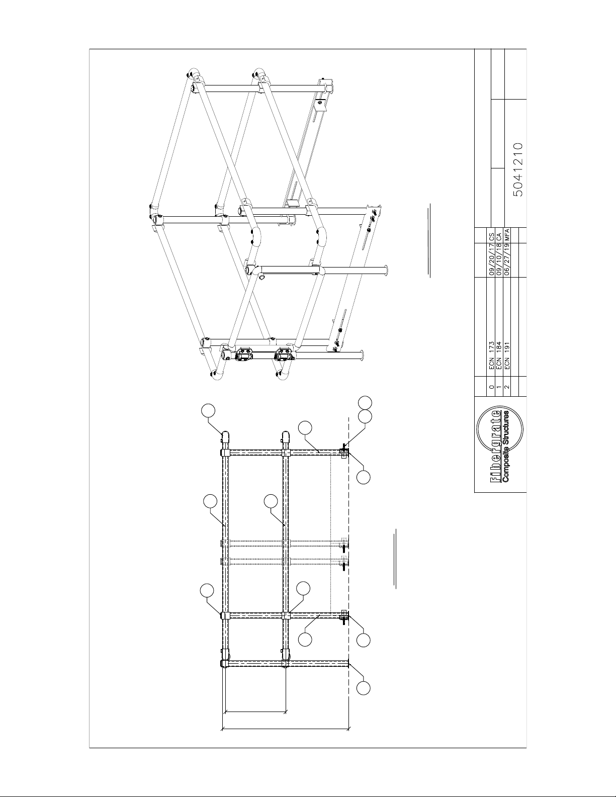
PN 5041210 (ASSEMBLY)-YL
DynaRound RG Hatch Guard
PLAN VIEW
WEIGHT = 152 lb
(69 kg)
2
4
12 Open Cross Over793201
8 Two Way Elbow793125
2Hatch Guard 55" Channel5041113
6 Caplugs Yellow Flanged Plug WWX-17793113
1
4McMaster 3/8"Ø x 4" U-Bolt W/ Nuts Zinc Plated PN 8875T858793114
8 End Cap - UV Coated7926150
4
Hatch Side Rail 74" YL
5041140 Hatch End Rail 52-1/2" YL
5041150 Hatch Post 42-3/8" YL
5041120 Hatch Gate Rail 11-1/4" YL
4
76 3/8"
[1941 mm]
74"
[1880 mm]
54 1/4"
[1378 mm] FOR 36x54 HATCH
6"
[152
mm]
36 1/4"
[921 mm]FOR 30x36 HATCH
30"
[762 mm]
12 3/16"
[310 mm]
52 1/2"
[1333 mm]
57 7/8"
[1471 mm]
A
A
B
B
Material Requirements for 5041210
4 3/8" Ø Nut78420010
12
7
8
3
4
5
2
6
15
1
13
14
12 3/8" Ø Washer78520011
49
12
6
9
10 11
7
12
13
14
3
30 1/4"
[768 mm]FOR 30x30 HATCH
30-36 x 30-54
50
5
Hatch Guard 3.25" Angle5041115
Hatch Post 42-3/8" w/Gate YL5041150.1
3/8" Ø x 1 1/4" Lg. Bolt754530
1 883304 Dynarail-Hatch Guard Installation Instructions16
Yellow
Hatch Post 42-3/8" w/Gate Support YL
1 5041150.217
17
DATE:
HATCH GUARD
N.T.S.
SCALE
DRAWING NUMBER
4
MFA
SHEET
DRAWN:
OF2
06/27/19
REV BYDATEDESCRIPTION
ELEVATION
3
48 11
13
13
42"
[1067 mm]
20 1/16"
[510 mm]
4 4
2
1
15 15
ISOMETRIC VIEW

DATE:
HATCH GUARD
N.T.S.
SCALE
DRAWING NUMBER
4
MFA
SHEET
DRAWN:
OF3
06/27/19
REV BYDATEDESCRIPTION
SECTION A-A SECTION B-B
15
12
15
12
1212
66
42"
[1067 mm]
20 1/16"
[510 mm]
20 1/16"
[510 mm]
42"
[1067 mm]
4 4 44
15 15
2
1
4 4
5
42 3/8"
[1076 mm]
Hatch Post 42 3/8" w/Gate YL 5
5041150.1
SHIP TRU-CLOSE HINGE
INSTRUCTIONS LOOSE WITH HATCH
GUARD. DO NOT TENSION HINGES
AFTER ATTACHING GATE TO POST.
17

1.9"Ø ROUND TUBE 12
DATE:
HATCH GUARD
N.T.S.
SCALE
DRAWING NUMBER
4
MFA
SHEET
DRAWN:
OF4
06/27/19
REV BYDATEDESCRIPTION
11 1/4"
[285 mm]
1.9"Ø ROUND TUBE 13
74"
[1880 mm]
1.9"Ø ROUND TUBE 14
52 1/2"
[1333 mm]
1.9"Ø ROUND TUBE 15
42 3/8"
[1076 mm]
SHOP ATTACHED
3
SHOP ATTACHED
3
5041120 5041130
5041140
5041150
1.9"Ø ROUND TUBE 5
42 3/8"
[1076 mm]
SHOP ATTACHED
3
5041150.1
42 3/8"
[1076 mm]
3 5/8"
[92 mm]
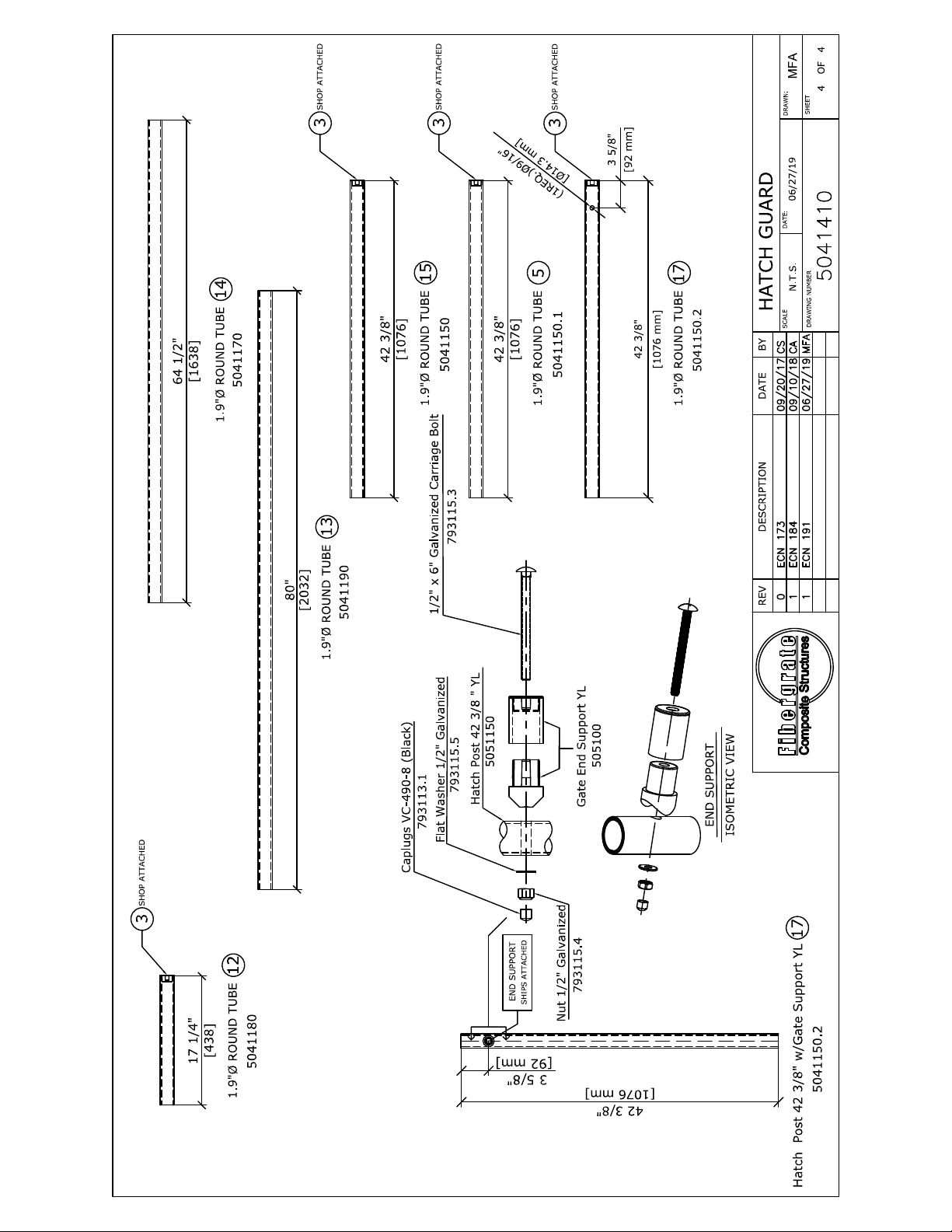
Hatch Post 42 3/8" w/Gate Support YL 17
5041150.2
1.9"Ø ROUND TUBE 17
42 3/8"
[1076 mm]
SHOP ATTACHED
3
5041150.2
3 5/8"
[92 mm]
END SUPPORT
(1REQ.)Ø9/16"
[Ø14.3 mm]
SHIPS ATTACHED
Hatch Post 42 3/8 " YL
5051150
Gate End Support YL
505100
Flat Washer 1/2" Galvanized
793115.5
Nut 1/2" Galvanized
793115.4
Caplugs VC-490-8 (Black)
793113.1 1/2" x 6" Galvanized Carriage Bolt
793115.3
END SUPPORT
ISOMETRIC VIEW

NUMBER
PARTITEM QTY
REQ'D
NO. DESCRIPTION
DATE:
HATCH GUARD
N.T.S.
SCALE
DRAWING NUMBER
4
MFA
SHEET
DRAWN:
OF1
06/27/19
REV BYDATEDESCRIPTION
PN 5041310 (ASSEMBLY)-YL
DynaRound RG Hatch Guard - 30-36 x 96-114
PLAN VIEW
WEIGHT = 176 LBS
(80 Kg)
4
2
12 Open Cross Over793201
8 Two Way Elbow793125
2
6 Caplugs Yellow Flanged Plug WWX-17793113
1
4
McMaster 3/8"Ø x 4" U-Bolt W/ Nuts Zinc Plated PN 8875T858
793114
8End Cap - UV Coated7926150
4
5041160 Hatch Side Rail 134" YL
5041140 Hatch End Rail 52-1/2" YL
5041120 Hatch Gate Rail 11-1/4" YL
4
Material Requirements for 5041310
4 3/8" Ø Nut10
12
7
8
3
4
5
2
6
14
1
13
12 3/8" Ø Washer11
49
136 3/8"
[3465 mm]
134"
[3404 mm]
114 1/4"
[2902 mm] FOR 36x114 HATCH
6"
[152
mm]
96 1/4"
[2445 mm] FOR 30x96 HATCH
30"
[762 mm]
12 3/16"
[310 mm]
52 1/2"
[1333 mm]
57 7/8"
[1471 mm]
C
C
D
D
12
6
9
10 11
7
12
13
14
4 5041150 Hatch Post 42-3/8" YL15
784200
785200
3
16 1 Dynarall-Hatch Guard Installation Instructions883304
3/8" Ø x 1 1/4" Lg. Bolt754530
Hatch Guard 55" Channel5041113
Hatch Guard 3.25" Angle5041115
Hatch Post 42-3/8" w/ Gate YL5041150.1
5
Yellow
Hatch Post 42-3/8" w/Gate Support YL
15041150.2
17
17

DATE:
HATCH GUARD
N.T.S.
SCALE
DRAWING NUMBER
4
MFA
SHEET
DRAWN:
OF2
06/27/19
REV BYDATEDESCRIPTION
ELEVATION
3
48 11
13
13
42"
[1067 mm]
20 1/16"
[510 mm]
4 4
2
1
15 15
ISOMETRIC VIEW

DATE:
HATCH GUARD
N.T.S.
SCALE
DRAWING NUMBER
4
MFA
SHEET
DRAWN:
OF3
06/27/19
REV BYDATEDESCRIPTION
SECTION C-C SECTION D-D
15
12
15
12
1212
66
42"
[1067 mm]
20 1/16"
[510 mm]
20 1/16"
[510 mm]
42"
[1067 mm]
4 4 44
15 15
1
4 4
5
42 3/8"
[1076 mm]
17
Hatch Post 42 3/8" w/Gate YL 5
5041150.1
SHIP TRU-CLOSE HINGE
INSTRUCTIONS LOOSE WITH HATCH
GUARD. DO NOT TENSION HINGES
AFTER ATTACHING GATE TO POST.

1.9"Ø ROUND TUBE 12
DATE:
HATCH GUARD
N.T.S.
SCALE
DRAWING NUMBER
4
MFA
SHEET
DRAWN:
OF4
06/27/19
REV BYDATEDESCRIPTION
11 1/4"
[285]
1.9"Ø ROUND TUBE 13
134"
[3404]
1.9"Ø ROUND TUBE 14
52 1/2"
[1333]
1.9"Ø ROUND TUBE 15
42 3/8"
[1076]
SHOP ATTACHED
3
SHOP ATTACHED
3
5041150.1
1.9"Ø ROUND TUBE 5
42 3/8"
[1076]
SHOP ATTACHED
3
5041150
5041160
5041120 5041140
42 3/8"
[1076 mm]
3 5/8"
[92 mm]
Hatch Post 42 3/8" w/Gate Support YL 17
5041150.2
1.9"Ø ROUND TUBE 17
42 3/8"
[1076 mm]
SHOP ATTACHED
3
5041150.2
3 5/8"
[92 mm]
(1REQ.)Ø9/16"
[Ø14.3 mm]
END SUPPORT
SHIPS ATTACHED
Hatch Post 42 3/8 " YL
5051150
Gate End Support YL
505100
Flat Washer 1/2" Galvanized
793115.5
Nut 1/2" Galvanized
Caplugs VC-490-8 (Black)
793113.1 1/2" x 6" Galvanized Carriage Bolt
793115.3
END SUPPORT
ISOMETRIC VIEW
793115.4

DATE:
HATCH GUARD
N.T.S.
SCALE
DRAWING NUMBER
4
MFA
SHEET
DRAWN:
OF1
06/27/19
REV BYDATEDESCRIPTION
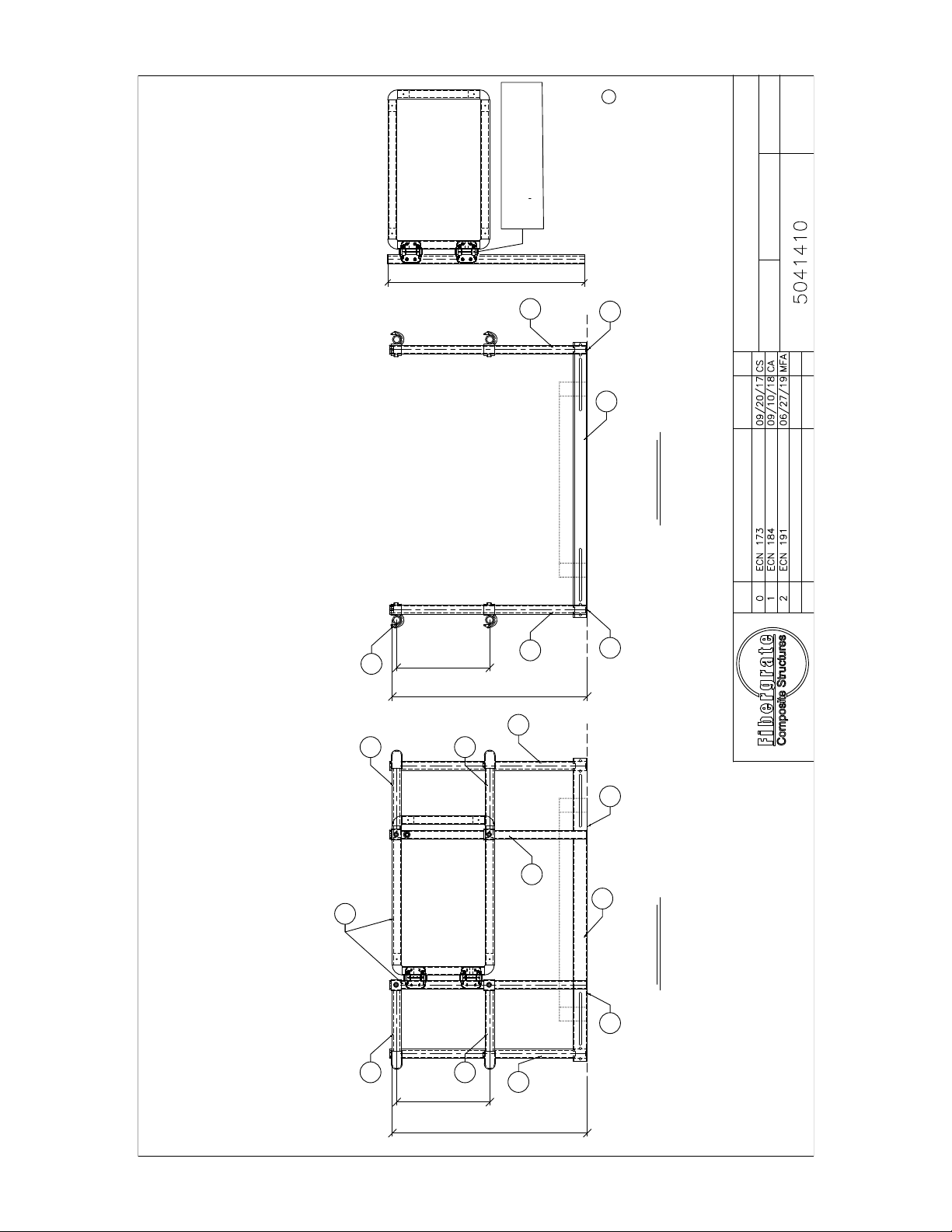
PN 5041410 (ASSEMBLY)-YL
DynaRound RG Hatch Guard - 42-48 x 42-60
WEIGHT = 163 LBS
(74 Kg)
PLAN VIEW
82 3/8"
[2093 mm]
80"
[2032 mm]
60 1/4"
[1530 mm] FOR 48x60 HATCH
6"
[152
mm]
42 1/4"
[1073 mm] FOR 42x42 HATCH
30"
[762 mm]
18 3/16"
[462 mm]
64 1/2"
[1638 mm]
69 7/8"
[1775 mm]
E
E
F
F
12
9
10 11
7
12
13
14
3
6
65 1/4"
[1657 mm]
NUMBER
PARTITEM QTY
REQ'D
NO.
2
DESCRIPTION
5041170
4
12 Open Cross Over793201
8 Two Way Elbow793125
6 Caplugs Yellow Flanged Plug WWX-17793113
1 Hatch Post 42-3/8" w/Gate YL5041150.1
4
McMaster 3/8"Ø x 4" U-Bolt W/ Nuts Zinc Plated PN 8875T858
793114
8 End Cap - UV Coated7926150
4
Hatch End Rail 64-1/2" YL
5041150 Hatch Post 42-3/8" YL
5041190 Hatch Side Rail 80" YL
4 Hatch Guard 3.25" Angle5041115
Material Requirements for 5041410
4 3/8" Ø Nut10
13
7
8
3
4
5
2
1
14
15
12 3/8" Ø Washer11
4 3/8" Ø x 1 1/4" Lg. Bolt9
4 5041180 Hatch Gate Rail 17-1/4" YL12
784200
785200
754530
6
16
2 Hatch Guard 67" Channel5041114
1 Dynarail-Hatch Guard Installation Instructions883304
5 Yellow
Hatch Post 42-3/8" w/Gate Support YL
1 5041150.217
17

DATE:
HATCH GUARD
N.T.S.
SCALE
DRAWING NUMBER
4
MFA
SHEET
DRAWN:
OF2
06/27/19
REV BYDATEDESCRIPTION
ELEVATION
3
48 11
13
13
42"
[1067 mm]
20 1/16"
[510 mm]
4 4
2
1
15 15
ISOMETRIC VIEW
DATE:
HATCH GUARD
N.T.S.
SCALE
DRAWING NUMBER
4
MFA
SHEET
DRAWN:
OF3
06/27/19
REV BYDATEDESCRIPTION
SECTION E-E SECTION F-F
15 15
12
12
42"
[1067 mm]
20 1/16"
[510 mm]
20 1/16"
[510 mm]
42"
[1067 mm]
4
15
12
12
4
15
66
1
4 4
5
42 3/8"
[1076 mm]
17
Hatch Post 42 3/8" w/Gate YL 5
5041150.1
SHIP TRU-CLOSE HINGE
INSTRUCTIONS LOOSE WITH HATCH
GUARD. DO NOT TENSION HINGES
AFTER ATTACHING GATE TO POST.
This manual suits for next models
5
Table of contents


