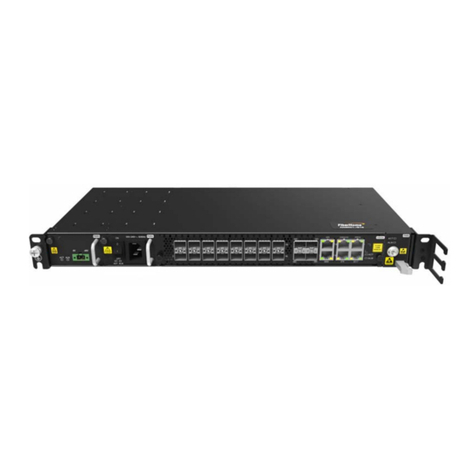
FiberHome AN6000 Series Guide

AN6000 Series
Optical Line Terminal Equipment
Hardware Description
Version: B
Code: MN000004289
FiberHome Telecommunication Technologies Co., Ltd.
March 2021


Thank you for choosing our products.
We appreciate your business. Your satisfaction is our goal.
We will provide you with comprehensive technical support
and after-sales service. Please contact your local sales
representative, service representative or distributor for any
help needed at the contact information shown below.
Fiberhome Telecommunication Technologies Co., Ltd.
Address: No. 67, Guanggu Chuangye Jie, Wuhan, Hubei, China
Zip code: 430073
Tel: +6 03 7960 0860/0884 (for Malaysia)
+91 98 9985 5448 (for South Asia)
+593 4 501 4529 (for South America)
Fax: +86 27 8717 8521
Website: http://www.fiberhome.com


Legal Notice
are trademarks of FiberHome Telecommunication Technologies Co., Ltd.
(Hereinafter referred to as FiberHome)
All brand names and product names used in this document are used for
identification purposes only and are trademarks or registered trademarks
of their respective holders.
All rights reserved
No part of this document (including the electronic version) may be
reproduced or transmitted in any form or by any means without prior
written permission from FiberHome.
Information in this document is subject to change without notice.


Contents
1Documentation Guide .....................................................................................1
2The AN6000-17 Subrack.................................................................................3
2.1 Appearance and Structure ................................................................4
2.2 Physical Parameters.........................................................................4
2.3 Slot Configuration .............................................................................6
2.4 Fan Unit............................................................................................7
3The AN6000-15 Subrack...............................................................................10
3.1 Appearance and Structure ..............................................................11
3.2 Physical Parameters.......................................................................11
3.3 Slot Configuration ...........................................................................13
3.4 Fan Unit..........................................................................................14
4The AN6000-7 Subrack ................................................................................17
4.1 Appearance and Structure ..............................................................18
4.2 Physical Parameters.......................................................................18
4.3 Slot Configuration ...........................................................................20
4.4 Fan Unit..........................................................................................21
5Cards ...........................................................................................................24
5.1 Card Structure ................................................................................25
5.2 Card Overview................................................................................27
5.3 Core Switch Card............................................................................29
5.3.1 HSCA...............................................................................29
5.4 Uplink Card.....................................................................................34
5.4.1 HU8A ...............................................................................34
5.4.2 KU1B ...............................................................................36
5.5 Power Card ....................................................................................38
5.5.1 PIBA.................................................................................38
5.6 GPON Interface Card......................................................................39

5.6.1 GPOA...............................................................................40
5.7 10G EPON Interface Card...............................................................43
5.7.1 Comparison Between 10G EPON Interface Cards .............43
5.7.2 EX8A................................................................................45
5.7.3 EXOA...............................................................................47
5.8 XG-PON Interface Card ..................................................................49
5.8.1 GX8A ...............................................................................49
5.9 PON Combo Interface Card ............................................................52
5.9.1 Comparison Between PON Combo Interface Cards...........53
5.9.2 GM8A...............................................................................58
5.9.3 GM8B...............................................................................60
5.9.4 GMOA ..............................................................................61
5.9.5 GNOA ..............................................................................63
5.9.6 GFOA...............................................................................65
5.10 Ethernet Interface Card...................................................................67
5.10.1 PXNA ...............................................................................67
5.11 Common Interface Card..................................................................70
5.11.1 CIOA ................................................................................70
6Modules .......................................................................................................73
6.1 Mappings Between Modules and Cards ..........................................74
6.2 PON Module...................................................................................75
6.2.1 GPON Optical Module ......................................................76
6.2.2 10G EPON Optical Module ...............................................76
6.2.3 XG-PON Optical Module ...................................................77
6.2.4 Combo PON Optical Module .............................................77
6.3 Ethernet Module .............................................................................79
6.3.1 GE Module .......................................................................79
6.3.2 10GE Optical Module........................................................80
6.3.3 100GE Optical Module......................................................81
7Wires and Cables .........................................................................................82
7.1 Cable Overview ..............................................................................83
7.2 Power Cable...................................................................................83

7.2.1 Subrack DC Power Cables for the PDP850A (3000064) ....84
7.2.2 Subrack DC Power Cables for the PDP260B (3000063) /
PDP296B (3000068).........................................................85
7.3 Protection Earth Ground Cable .......................................................86
7.3.1 Subrack Protection Earth Ground Cable............................86
7.3.2 Cabinet Protection Earth Ground Cable.............................87
7.3.3 Cabinet Protection Earth Ground Cable.............................88
7.4 Alarm Cable....................................................................................89
7.4.1 Alarm Cable for the Head of Row Cabinet .........................89
7.4.2 Subrack Alarm Cable ........................................................90
7.5 Fiber Jumper ..................................................................................91
7.6 Straight-Through Cable...................................................................93
7.7 Time Cable .....................................................................................94
7.8 Clock Cable....................................................................................95
7.9 Serial Port Line ...............................................................................96
7.10 Dry Contact Cable ..........................................................................97
7.11 Environment Monitoring Unit Connection Cable...............................98
8Cabinets.....................................................................................................100
8.1 Cabinet Overview .........................................................................101
8.2 Detailed Dimensions of the Cabinets.............................................102
8.3 Equipment Layout for the AN6000-17............................................104
8.4 Equipment Layout for the AN6000-15............................................105
8.5 Equipment Layout for the AN6000-7..............................................107
9PDPs..........................................................................................................110
9.1 PDP Overview .............................................................................. 111
9.2 PDP260B (3000063)..................................................................... 111
9.2.1 Appearance.................................................................... 111
9.2.2 Specification...................................................................112
9.2.3 Connectors on the Panel................................................. 113
9.2.4 Connection ..................................................................... 114
9.2.5 PDP Power Cable........................................................... 115
9.2.6 PDP Protection Earth Ground Cable ............................... 116

9.3 PDP850A (3000064).....................................................................117
9.3.1 Appearance....................................................................117
9.3.2 Specification...................................................................117
9.3.3 Panel Terminals .............................................................. 119
9.3.4 Connection .....................................................................121
9.3.5 Lightning Protection Module............................................121
9.3.6 PDP Power Cable...........................................................122
9.3.7 PDP Earth Ground Cable ................................................123
9.4 PDP296B (3000068).....................................................................124
9.4.1 Appearance....................................................................124
9.4.2 Specification...................................................................124
9.4.3 Connectors on the Panel.................................................126
9.4.4 Connection .....................................................................128
9.4.5 Lightning Protection Module............................................128
9.4.6 PDP Power Cable...........................................................129
9.4.7 PDP Protection Earth Ground Cable ...............................130

1Documentation Guide
Document Orientation
Hardware Description gives a detailed introduction to the hardware components of
the AN6000 Series. This manual is designed for readers who want to have a
detailed knowledge about the hardware of the equipment or need the hardware
information to guide them in O&M.
Intended Readers
uMarketing personnel
uCommissioning engineers
uOperation and maintenance engineers
Version Information
Version Description
A Initial version.
BAdds the GM8B, GFOA, KU1B and PXNA cards, laser signs,
and precautions for cabinet dust screens.
Content
Chapter Summary
The AN6000-17 Subrack
The AN6000-15 Subrack
The AN6000-7 Subrack
uAppearance and structure
uPhysical parameters
uSlot configuration
uFan unit
Cards
uCard structure and overview
uInterfaces and indicator LEDs on card panels
uTechnical specifications and modules
uFunctions
uWorking principles
Modules
uMappings between modules and cards
uModule types and specifications
Wires and Cables
uCable overview
uCable structure and specifications
Version: B 1

AN6000 Series Optical Line Terminal Equipment Hardware Description
Chapter Summary
Cabinets
uCabinet overview
uAppearances and detailed dimensions of cabinets
uEquipment layout
PDPs
uPDP overview
uAppearances and specifications of PDPs
uPanel connectors, connections, power cables and earth
ground cables of PDPs
Related Documentation
Document Applied to
AN6000 Series Optical Line Terminal Equipment
Product Description Network planning
AN6000-17 Optical Line Terminal Equipment Quick
Installation Guide
Network deployment phase /
network maintenance
AN6000-15 Optical Line Terminal Equipment Quick
Installation Guide
Network deployment / network
maintenance
AN6000-7 Optical Line Terminal Equipment Quick
Installation Guide
Network deployment / network
maintenance
AN6000 Series Optical Line Terminal Equipment
UNM2000 Configuration Guide
Network deployment / network
maintenance
AN6000 Series Optical Line Terminal Equipment CLI
Configuration Guide
Network deployment / network
maintenance
AN6000 Series Optical Line Terminal Equipment CLI
Reference
Network deployment / network
maintenance
AN6000 Series Optical Line Terminal Equipment Alarm
and Event Reference
Network deployment / network
maintenance
2Version: B

AN6000 Series Optical Line Terminal Equipment Hardware Description
2.1 Appearance and Structure
No. Name Function
①Horizontal card slot Houses a fan unit.
②Vertical card slots Accommodate cards to implement various
functions of the equipment.
③ESD protection earth ground fastener Connects with an ESD protection unit.
④Mounting ears Secure the subrack in a cabinet.
⑤Fiber puller hanger Holds a fiber puller.
⑥Subrack earth ground point Connects with the subrack protection earth
ground cable.
2.2 Physical Parameters
Dimensions
Item Specification
Dimensions of a subrack with mounting ears for 21-inch
cabinets (H × W × D)Note 1 486 mm × 530 mm × 282 mm
Note 1: The AN6000-17 subrack is equipped with mounting ears for 21-inch cabinets by
default.
4Version: B

2 The AN6000-17 Subrack
Weight
Item Specification
Weight of an empty subrack (excluding the fan unit) 14 kg
Weight of an empty subrack (including the fan unit) 19 kg
Operating Environment
Item Specification
Operating temperature -40℃to 65℃
Operating relative humidity 5% to 95% (non-condensing)
Storage temperature -40℃to 70℃
Relative humidity for storage 5% to 95% (non-condensing)
Power Supply Parameters
Item Specification
Maximum input current 63 A
Power supply mode DC (two channels of power supplies forming redundancy
protection)
Working voltage range -38.4 V to -57.6 V
Rated voltage -48 V
Overall Power Consumption
The overall power consumption is measured under the following conditions:
uWorking voltage: -53.5 V DC
uRoom temperature: 25℃(static power consumption and typical power
consumption) or 55℃(maximum power consumption)
uStatic power consumption: All the broadband ports are deactivated.
uTypical power consumption: 50% of the broadband ports are concurrently
activated.
uMaximum power consumption: 100% of the broadband ports are concurrently
activated.
Version: B 5

AN6000 Series Optical Line Terminal Equipment Hardware Description
Typical Configuration Static Power
Consumption
Typical Power
Consumption
Maximum Power
Consumption
2 × HSCA + 17 × GNOA + 2 ×
PIBA + FAN + CIOA 1211 W 2093 W 2449 W
Note 1: The equipment can only be used together with a PDP with a rated current of 63 A. For
details of the matching PDPs, see PDPs.
Instruction:
For other card configurations, calculate the overall power consumption according to this
formula: overall power consumption = power consumption of 2 core switch cards +
power consumption of 17 service cards + power consumption of 2 power cards + power
consumption of the fan unit + power consumption of the common interface card. For
power consumption of each card, refer to Card Overview.
2.3 Slot Configuration
Slot Distribution
The AN6000-17 subrack provides 22 vertical slots and one horizontal slot.
Card Supported
The slots can be classified as follows according to the cards they house:
Type Slot Card Supported
Service card slot 1-8 and 11-19 GPOA, EX8A, EXOA, GX8A, GM8A, GM8B,
GMOA, GNOA, GFOA, PXNANote 1
Uplink card slot 18, 19 HU8A, KU1B
6Version: B

2 The AN6000-17 Subrack
Type Slot Card Supported
Core switch card slot 9, 10 HSCA
Fan unit slot 23 FAN
Power card slot 24, 25 PIBA
Common interface card slot 26 CIOA
Note 1: The PXNA card can be applied to any service card slot and used as an uplink card.
2.4 Fan Unit
Model
The model number of the fan unit for the AN6000-17 subrack is 405000320.
Appearance
Working Principle
uLocated at the top of the subrack, the fan unit facilitates air cooling in the
subrack by drawing air. A flow of cooling air is drawn into the subrack from its
bottom. After passing through each working card in the subrack, the air is
exhausted from the top of the subrack.
Version: B 7

AN6000 Series Optical Line Terminal Equipment Hardware Description
uThe fan unit is configured with a fan monitoring board, which can detect the
working status of fans. The monitoring board provides interfaces for
communication with the core switch card of the equipment, and sends the
monitoring information to the core switch card regularly.
uThe fan unit provides seven speed levels (1 to 7, from the lowest to the highest).
The fan speed can be regulated in manual mode or intelligent mode.
4In manual mode, the fan unit operates at the speed set on the EMS.
4In intelligent mode, the core switch card of the equipment automatically
selects a speed for the fan unit according to the card temperature detected,
and the fan unit operates at the selected speed.
Indicator LEDs
Identifier Meaning Color Status Description
ACT Working
indicator LED Green
ON The fan unit is powered on.
OFF The fan unit is not powered on
as expected.
8Version: B

2 The AN6000-17 Subrack
Identifier Meaning Color Status Description
ALM Alarm indicator
LED Red
ON The fan unit is faulty.
Blinking The fan has its speed regulated
automatically.
OFF The fan unit is functioning
properly.
Technical Specifications
Item Specification
Dimensions (H × W × D) 60 mm × 494 mm × 269.5 mm
Weight 5.0 kg
Static / typical power consumption (when the fan unit
is operating at speed level 3) 56 W
Maximum power consumption (when the fan unit is
operating at speed level 7) 210 W
Version: B 9
Table of contents
Other FiberHome Touch Terminal manuals


