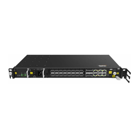
FiberHome HG6145F User manual

HG6145F
GPON Optical Network Terminal
Product Manual
Version: A
FiberHome Telecommunication Technologies Co., Ltd.
November 2020


Thank you for choosing our products.
We appreciate your business. Your satisfaction is our goal.
We will provide you with comprehensive technical support
and after-sales service. Please contact your local sales
representative, service representative or distributor for any
help needed at the contact information shown below.
Fiberhome Telecommunication Technologies Co., Ltd.
Address: No. 67, Guanggu Chuangye Jie, Wuhan, Hubei, China
Zip code: 430073
Tel: +6 03 7960 0860/0884 (for Malaysia)
+91 98 9985 5448 (for South Asia)
+593 4 501 4529 (for South America)
Fax: +86 27 8717 8521
Website: http://www.fiberhomegroup.com


Legal Notice
are trademarks of FiberHome Telecommunication Technologies Co., Ltd.
(Hereinafter referred to as FiberHome)
All brand names and product names used in this document are used for
identification purposes only and are trademarks or registered trademarks
of their respective holders.
All rights reserved
No part of this document (including the electronic version) may be
reproduced or transmitted in any form or by any means without prior
written permission from FiberHome.
Information in this document is subject to change without notice.


Safety Precautions
For your correct and safe operations on the equipment, please carefully read and
strictly observe the following safety instructions:
uHigh optical power can cause bodily harm, especially to eyes. Never look
directly into the end of the optical transmitter fiber jumper or the end of its active
connector.
uExercise care if you must bend fibers. If bends are necessary, the fiber bending
radius should never be less than 38 mm.
uOverloaded power sockets or damaged cables and connectors may cause
electric shock or fire. Regularly check related electric cables. If any of them is
damaged, replace it immediately.
uUse the power supply adapter provided in the package only. Using other
adapters may cause equipment damage or operation failures.
uInstall the equipment in a well ventilated environment without high temperature
or direct sunlight to protect the equipment and its components from overheating,
which can result in damage.
uDisconnect the power in lightning weather and disconnect all the wires and
cables on the device (such as the power cable, network cable and phone
cable), so as to prevent device from being damaged by lightning.
uDo not place this equipment in damp or near moisture environment. Water will
lead to abnormal operation of device and even the danger caused by short
circuit.
uDo not lay this equipment on an unsteady base.
I


Contents
Safety Precautions..................................................................................................I
1Documentation Guide .....................................................................................1
2Product Introduction........................................................................................2
2.1 Product Positioning...........................................................................3
2.2 Product Specifications ......................................................................3
2.3 Interface Specifications.....................................................................4
2.3.1 GPON Interface ..................................................................4
2.3.2 LAN Interface......................................................................4
2.3.3 POTS Interface...................................................................5
2.3.4 Wi-Fi Interface ....................................................................5
2.3.5 USB Interface .....................................................................6
2.4 Introduction to the HG6145F .............................................................6
2.4.1 Appearance........................................................................6
2.4.2 Product Characteristics.......................................................9
2.4.3 Functions and Features ....................................................11
2.4.4 Technical Specifications....................................................15
3Handling Common Problems ........................................................................16
3.1 Power Status Indicator LED Extinguished........................................17
3.2 Register Status Indicator LED Extinguished ....................................17
3.3 Optical Signal Status Indicator LED Blinking....................................17
3.4 Ethernet Interface Status Indicator LED Extinguished ......................17
3.5 Failing to Detect ONT Using Wi-Fi ...................................................18
3.6 Failing to Access Local Web Login GUI and Failing to Ping
192.168.1.1 ....................................................................................18
3.7 Failing to Access Internet Using the LAN Port..................................18
3.8 Failing to Access Internet Using Wi-Fi .............................................19
3.9 Measured Internet Access Rate Lower or Higher Than the Standard
Value..............................................................................................19

3.10 Test of Voice Service Failed ............................................................19
4Standards and Protocols...............................................................................20
Appendix A Abbreviations ............................................................................23

11 Documentation Guide
Document Orientation
HG6145F Product Manual introduces the positioning, features, functions, technical
specifications of the ONT (Optical Network Terminal) product HG6145F as well as
handling of common problems, so that readers can have an overall knowledge
about the HG6145F.
Intended Readers
uMarketing personnel
uCommissioning engineers
uOperation and maintenance engineers
Version Information
Version Version Information
A Initial version
Content
Chapter Content
Product Introduction
uProduct positioning
uProduct specifications
uInterface specifications
uIntroduction to the HG6145F
Handling Common Problems
Introduces how to handle common problems encountered
during product operation and service test, including
abnormal status of indicator LEDs, failing to access the
Internet, failure of voice service test, etc.
Standards and Protocols International standards and communications protocols
Version: A 1

2 Product Introduction
2.12.1 Product Positioning
The HG6145F is an FTTH-type GPON ONT. It provides users with communication
and entertainment services in the form of data, voice, video, and so on, to meet the
integrated access demand of families and small-scaled enterprises.
See Figure 2-1 for the network positioning of the HG6145F.
Figure 2-1 Network Application of the HG6145F
2.22.2 Product Specifications
The tables below list the interfaces on the HG6145F and the services supported by
the ONT for users' reference on ONT configuration.
Table 2-1 Interfaces Supported by the HG6145F
ONT Type Ethernet Interface
Quantity
POTS
Interface
Quantity
Wi-Fi Interface
USB
Interface
Quantity
CATV
Interface
Quantity
HG6145F 4 (GE) 1√(2.4 GHz, 5 GHz) 2 -
Version: A 3

HG6145F GPON Optical Network Terminal Product Manual
Table 2-2 Service Types Supported by the HG6145F
ONT Type Internet Service Multicast Service Voice Service Wi-Fi Service
HG6145F √ √ √ √
Note: “√”indicates “supported”;“×”indicates “not supported”.
Service Reliability
The HG6145F supports MTBF up to 30 000 hours.
2.32.3 Interface Specifications
2.3.12.3.1 GPON Interface
Table 2-3 GPON Interface Specifications
Parameter Specification
Standard compliance ITU-T G.984, Class B+
Transmission rate Rx: 2.5 Gbit/s; Tx: 1.25 Gbit/s
Interface mode Single-mode
Interface type SC/UPC
Maximum transmission distance 20 km
Central wavelength Tx: 1310 nm; Rx: 1490 nm
Optical power Tx optical power: 0.5 dBm to 5.0 dBm
Rx optical power: -8 dBm to -29 dBm
Extinction ratio More than 10 dB
Receiving sensitivity -27 dBm to -29 dBm
Maximum overload optical power -8 dBm
2.3.22.3.2 LAN Interface
Table 2-4 LAN Interface Specifications
Parameter Specification
Standard compliance IEEE 802.3ab
Interface type RJ-45
Interface rate 10 Mbit/s, 100 Mbit/s or 1000 Mbit/s
Maximum transmission distance 100 m
4Version: A

2 Product Introduction
Table 2-4 LAN Interface Specifications (Continued)
Parameter Specification
Working mode Supports full-duplex or half-duplex and 10/100/1000
M auto negotiation.
Specifications of the cable used CAT-5 unshielded twisted pair
2.3.32.3.3 POTS Interface
Table 2-5 POTS Interface Specifications
Parameter Specification
Interface type RJ-11
Transmission rate 64 Kbit/s
Cable type Twisted-pair cable
Line code PCM
2.3.42.3.4 Wi-Fi Interface
Table 2-6 Wi-Fi Interface Specifications
Parameter Specification
Standard compliance IEEE 802.11 a/b/g/n/ac/ax
Operating band 2.4 GHz / 5 GHz
Specifications
Supports four SSIDs and 13 working channels for the 2.4 GHz band
as well as four SSIDs and 24 working channels for the 5 GHz band.
Supports automatic rate adjustment and launched power adjustment
for both the 2.4 GHz band and the 5 GHz band.
Authentication mode OPEN, SHARED, WPA-PSK, WPA2-PSK, WPA-PSK/WPA2-PSK,
WPA3-SAE and WPA2-PSK/WPA3-SAE
Encryption mode WEP, TKIP, AES and TKIP/AES
Version: A 5

HG6145F GPON Optical Network Terminal Product Manual
2.3.52.3.5 USB Interface
Table 2-7 USB Interface Specifications
Parameter Specification
Standard compliance USB2.0
Transmission rate 20 MB/s
2.42.4 Introduction to the HG6145F
2.4.12.4.1 Appearance
The following describes the appearance of the HG6145F, including the overall look,
interfaces, buttons, and indicator LEDs.
Note:
The pictures here are only for reference.
Appearance
The overall appearance of the HG6145F is shown in Figure 2-2.
6Version: A

2 Product Introduction
Figure 2-2 Overall Outlook of the HG6145F
Interface and Button
Table 2-8 Interfaces and Buttons of the HG6145F
Interface and Button Description Function
WPS 2.4G/5G WPS button Enables or disables 2.4G/5G WPS.
WLAN 2.4G/5G WLAN button Enables or disables 2.4G/5G WLAN.
Phone Telephone interface Connects to the user's telephone.
LAN1 to LAN4 Ethernet interface Connects with the computer, IP router or IP set top box.
USB1, USB2 USB Host interface Connects to the USB interface storage device.
Power Power interface Connects with the power adapter.
On/Off Power switch Turns on or off the power for the equipment.
Reset Reset button Pressing down the button for more than 5 seconds to
restore the factory settings and reboot the equipment.
PON Fiber interface Connects with optical fiber for uplink access.
Version: A 7

HG6145F GPON Optical Network Terminal Product Manual
Indicator LED Description
Indicator LEDs of the HG6145F are located on the front panel of the equipment.
Table 2-9 Indicator LEDs on the HG6145F
Indicator LEDs Meaning Color Status Status Description
Power Power status
indicator LED Green
ON The equipment is powered on.
OFF The equipment is not powered on.
PON Register status
indicator LED Green
ON The ONT is activated.
Blinking The ONT is being activated.
OFF Activation of the ONT is not yet started.
LOS Optical signal status
indicator LED Red
Blinking The equipment has not received the optical
signal.
OFF The equipment has received the optical
signal.
Internet Broadband network
status indicator LED Green
ON Connection to the broadband network is
normal.
Blinking Connection to the broadband network is
normal with data transmission.
OFF Not connected to the broadband network.
WLAN
2.4G/5G wireless
signal status
indicator LED
Green
ON The 2.4G/5G wireless interface is enabled.
Blinking The 2.4G/5G wireless interface is transmitting
/ receiving data.
OFF The 2.4G/5G wireless interface is disabled.
WPS 2.4G/5G WPS status
indicator LED Green
ON The 2.4G/5G WPS is enabled, and the Wi-Fi
terminal has been connected to the ONT.
Blinking The 2.4G/5G WPS is being used in
negotiation.
OFF The 2.4G/5G WPS is not enabled, or the Wi-Fi
terminal is not connected to the ONT.
USB1, USB2 USB indicator LED Green ON The USB is connected.
OFF The USB is not connected.
LAN1 to LAN4 Ethernet interface
status indicator LED Green
ON The interface is connected to the user terminal
and no data is transmitted.
Blinking The interface is transmitting / receiving data.
OFF The interface is not connected to the user
terminal.
Phone Phone port status
indicator LED Green
ON The port is registered in the softswitch system.
Blinking Service flow is found at the port.
8Version: A

2 Product Introduction
Table 2-9 Indicator LEDs on the HG6145F (Continued)
Indicator LEDs Meaning Color Status Status Description
OFF The port is not registered in the softswitch
system.
2.4.22.4.2 Product Characteristics
The HG6145F can be used together with the OLT equipment to make up a GPON
system and access multiple services for users. The HG6145F has the following
characteristics:
1. GPON access capability
uConforms to ITU-T G.984 series of standards, with good interoperability.
uProvides large-capacity GPON transmission bandwidth: supports 2.5 Gbit/s for
the downlink rate and 1.25 Gbit/s for the uplink rate.
uSupports the DBA (Dynamic Bandwidth Allocation) algorithm.
uSupports long-haul transmission. The maximum transmission distance can
reach 20 km.
2. Abundant service types
The equipment provides abundant physical interfaces on the subscriber side to
access multiple services such as Internet access, video, voice and home storage
services.
3. Wi-Fi wireless access
uThe equipment provides Wi-Fi wireless access based on IEEE 802.11
a/b/g/n/ac/ax to set up safe and reliable wireless network for users.
uCompatible with IEEE 802.11 a/b/g/n/ac/ax and passed Wi-Fi Alliance
authentication, with good compatibility with other WLAN devices.
uSupports eight SSIDs (four SSIDs for the 2.4 GHz band and another four
SSIDs for the 5 GHz band) so that users can set different wireless networks as
needed.
Version: A 9

HG6145F GPON Optical Network Terminal Product Manual
uSupports multiple authentication and encryption modes to provide users with
safe and reliable wireless access mode.
4. Network storage and file sharing
uProvides two USB interfaces for connection with the USB interface storage
devices to provide convenient network storage and file sharing service.
uThe USB interfaces support plug-and-play and hot insertion.
uSupports configuration of the USB function based on the Web page to facilitate
file sharing in the family network.
uSupports the FTP-based network storage to provide FTP client end and FTP
server end functions. Users can download the files on the public network FTP
server to the USB interface storage devices or visit the USB interface storage
devices on the ONT via the FTP client end on the PC.
5. Gateway function
uServes as home gateway and provides abundant and reliable gateway
functions.
uFunctions as the DHCP Server to cater for application demands in different
scenarios.
uSupports configuring protection against DoS attack, filtering of MAC addresses,
IP addresses and URL addresses, firewall and ACL rules to guarantee safe
operation of the equipment.
6. Remote automatic provisioning of services, maintenance and management
uThe equipment adopts the management based on TR-069 and OMCI, and
supports TR-069 over OMCI. It can manage terminal services without IP
network, which facilitates automatic provisioning, maintenance and
management of services remotely.
uSupports configuring the global profile and delivering the XML configuration file
on the network management system. Only a few changes are required to
deliver the ONT services in a batch manner and make network adjustment.
uSupports configuring the user-defined upgrade policies on the network
management system so that the equipment can be upgraded automatically
after being powered on.
10 Version: A
Table of contents
Other FiberHome Touch Terminal manuals


