FiberLabs OTM-1550L User manual
Technical passport / OTM-1550L
OTM-1550L
Intelligent Direct Modulated
Optical Transmitter Operating
Manual

Technical passport / OTM-1550
12-2016-v4
Table of Contents
Table of Contents ...................................................................................................... - 1 -
1. Overview............................................................................................................... - 2 -
1.1 About This Manual ...................................................................................... - 2 -
1.2 Product Description ..................................................................................... - 2 -
1.3 Product Applications.................................................................................... - 3 -
2. Technique Parameters ........................................................................................... - 4 -
3. Panel Interface and Menu System Description..................................................... - 5 -
3.1 Front Panel................................................................................................... - 5 -
3.1.1 Indicator Description ......................................................................... - 5 -
3.2 Rear Panel .................................................................................................... - 6 -
3.3 Power Module.............................................................................................. - 6 -
3.3.1 220V Power Module .......................................................................... - 6 -
3.4 Menu Operation ........................................................................................... - 7 -
3.4.1 Main Menu......................................................................................... - 7 -
3.4.2 Display Menu..................................................................................... - 8 -
3.4.3 Set Menu .......................................................................................... - 10 -
3.4.4 Alarm Menu ..................................................................................... - 11 -
4. Installing the OTM-1550L Optical Transmitter.................................................. - 12 -
4.1 Receiving and Inspecting........................................................................... - 12 -
4.2 Precautions................................................................................................. - 12 -
4.3 Mounting OTM-1550L .............................................................................. - 12 -
4.3.1 Mounting the OTM-1550L in the Rack ........................................... - 12 -
4.3.2 Connecting the RF Cables ............................................................... - 13 -
4.3.3 Connecting the Optical Fiber Cables ............................................... - 13 -
4.3.4 Connecting the Ethernet Cable ........................................................ - 13 -
4.3.5 Connecting Power............................................................................ - 14 -
5. Communication Setup......................................................................................... - 14 -
5.1 RS232 Communication Interface Description........................................... - 14 -
5.2 Set up the Hyper Terminal ......................................................................... - 14 -
5.3 Operating Parameters Configuration ......................................................... - 16 -
5.4 Remote Monitoring: SNMP....................................................................... - 20 -
6. Maintenance and Troubleshooting...................................................................... - 21 -
6.1 Cleaning Fiber Optic Connectors............................................................... - 21 -
6.1.1 Cleaning Patch Cord or Pigtail Fiber Optical Connectors............... - 21 -
6.2 Troubleshooting ......................................................................................... - 22 -
6.3 After-sales Service Description.................................................................. - 22 -
6.4 Disclaimer.................................................................................................. - 22 -

Technical passport / OTM-1550
12-2016-v4
1. Overview
1.1 About This Manual
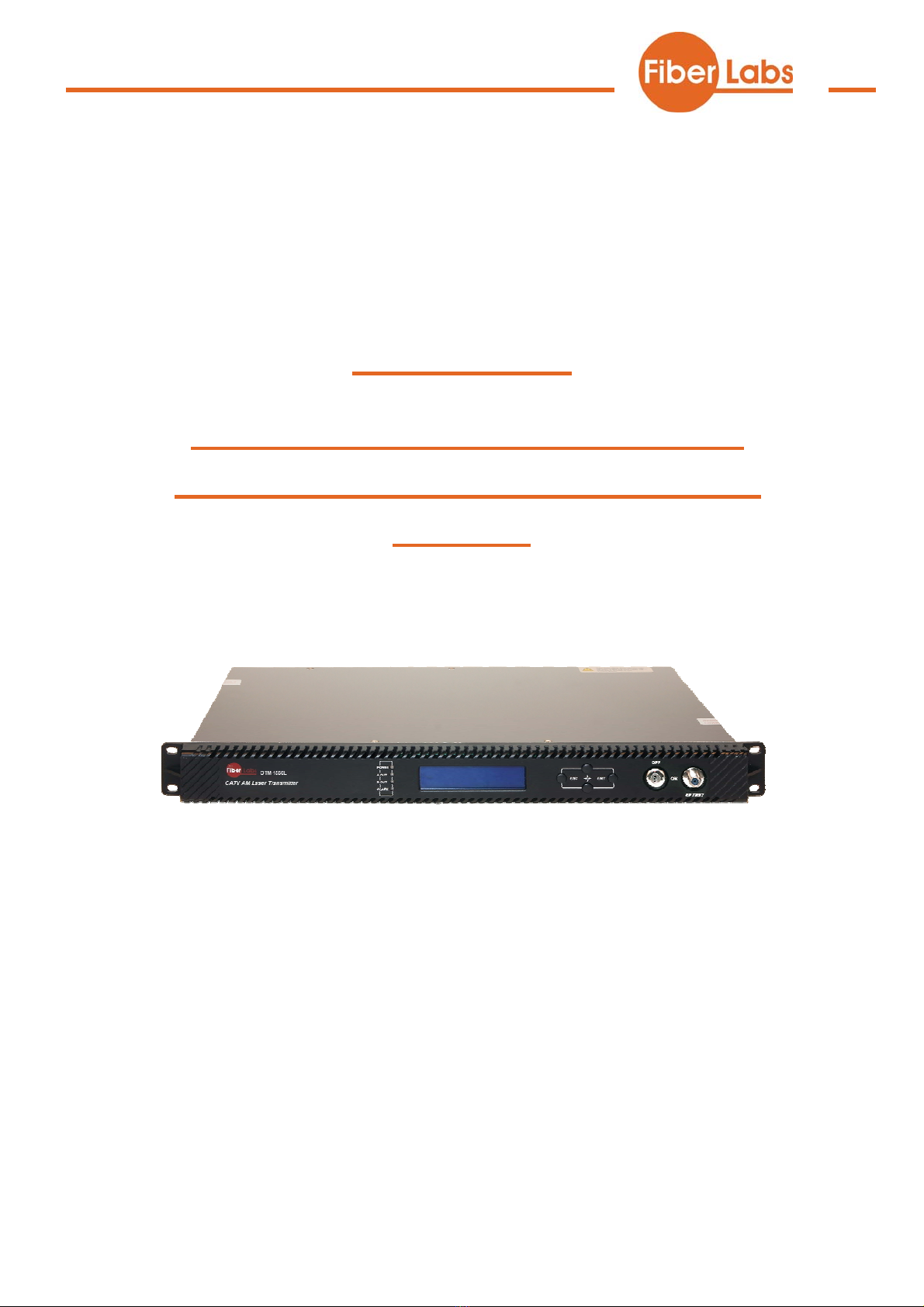
This instruction manual is a complete guide to install and operate the (1RU)
OTM-1550L optical transmitter. Please read the entire manual before beginning
installation.
This manual applies to OTM-1550L optical transmitter.
• Chapter 1 gives general information about the OTM-1550L optical transmitter.
• Chapter 2 describes the complete technical specifications of OTM-1550L.
• Chapter 3 describes the front/rear panel interfaces and menu system.
• Chapter 4 tells you how to install OTM-1550L optical transmitter.
• Chapter 5 tells you the communication setting of OTM-1550L.
• Chapter 6 describes maintenance and what to do in the event of problems.
1.2 Product Description
OTM-1550L intelligent directly modulated optical transmitter is mainly used in
1550nm optical fiber transmission system. Adopt advanced electronic dispersion
compensation technology, accurately compensate according to the actual transmission
distance by 1km stepping. The maximum compensated distance up to 50km.
OTM-1550L intelligent directly modulated optical transmitter is the most
important equipment to construct the CATV network. It mainly used for the
value-added services of TV image signal, digital television signal, telephone voice
signal and data (or compressed data) signal. By built-in WDM, multiplex the inter-cut
optical signal and the main optical signal then output. After setting required optical
difference, the perfect adjustable optical attenuation function can automatic control
the inserted optical signal according to the main optical signal, realize inter-cut system
full automatic adjustment. Provide high quality low cost solution for all-optical relay
1550 optical fiber CATV system, and local value-added services inter-cut.
Characteristics:
1. Patent pre-distortion circuit.
2. The optical fiber distance is adjustable according to the actual use condition by
1km stepping.
3. OTM-1550LⅡ: Built-in WDM, multiplex the inserted optical signal and the main
optical signal then output.
4. OTM-1550L Ⅲ: Built-in WDM and adjustable attenuator.

Technical passport / OTM-1550
12-2016-v4
Model Selection:
OTM-1550L-I: standard 1550nm directly modulated optical transmitter, the default
optical output power is 10mW, and the optical output wavelength can choose ITU
standard wavelength.
OTM-1550L-II: on the base of OTM-1550L-I, add inter-cut function and built-in
WDM. The WDM specification please specify when ordering.
OTM-1550L-III: on the base of OTM-1550L-II, add VOA Variable Optical
Attenuator, can adjust the signal optical power intensity by the menu options on the
front panel.
Block Diagram
OTM-1550L directly modulated optical transmitter block diagram
OTM-1550Linter-cut part block diagram
1.3 Product Applications
• 1550nm Optical fiber transmission system
• Construct the CATV network
• Local value-added services inter-cut

Technical passport / OTM-1550
12-2016-v4
2. Technique Parameters
Item Unit Technique Parameters
Output optical power mW 10
Optical wavelength nm 1550±10 (have to be ITU wavelength when
with inter-cut function)
Dispersion compensation
distance Km ≤50
Laser type DFB laser
Optical modulation mode Direct optical intensity modulation
Optical connector type FC/APC or SC/APC
Frequency range MHz 47-862/1003
RF input level dBuV 75-85
Flatness in band dB ±0.75
RF input impedance Ω75
Input return loss dB ≥16
C/CSO dB ≥60
C/CTB dB ≥65
C/N dB ≥51
25Km optical fiber, 0dB
received
AGC control range dB ±5
MGC control range dB 0-20
Supply voltage V AC 110V-250V (50Hz)
Consumption W 30
Operating temperature ℃0 -- 45
Storage temperature ℃-20 -- +65
Relative humidity % Max 95% no condensation
Dimension mm 483(L)×380(W)×44(H)
Special instructions: The performance parameters of this manual according to the
measuring method of GY/T 143-2000 <Specifications and methods of measurement
on AM optical transmitter and receiver used in CATV systems>, and tested under the
specified test conditions.
Technical passport / OTM-1550
12-2016-v4
3. Panel Interface and Menu System Description
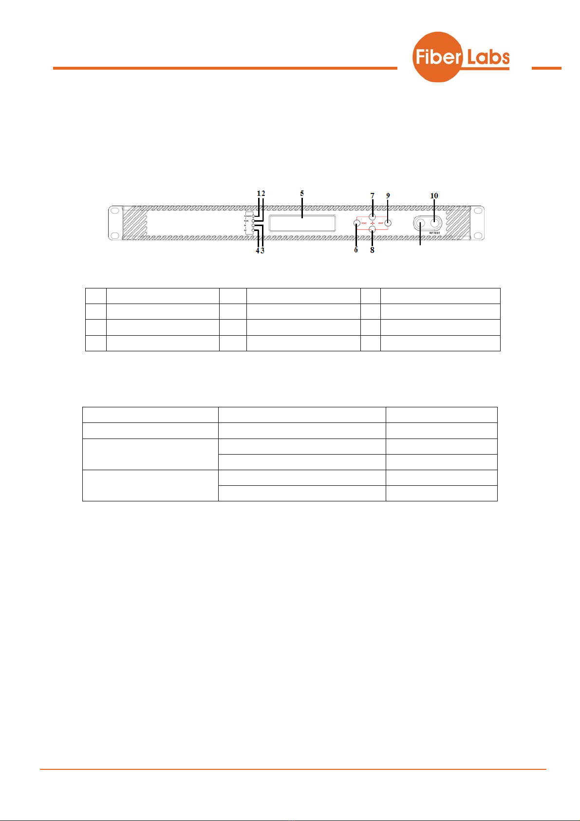
3.1 Front Panel
Front panel schematic diagram
1 Power indicator 2 Running indicator 3 Laser indicator
4 RF input indicator 5 LCD 6 ESC key
7 UP key 8 DOWN key 9 Enter key
10 RF output test port 11 Laser switch
11
3.1.1 Indicator Description
Power indicator (POWER) Power on LED green
Running indicator (RUN) Run normally LED flash green
Laser OFF LED red
Laser indicator Laser ON LED green
No output or exceed the normal range LED flash red
RF input indicator (RF) Normal LED green

Technical passport / OTM-1550
12-2016-v4
3.2 Rear Panel
Rear Panel schematic diagram
No. Name Remark
1 Fan
2 RF input
3 Local RF input Generally reserved
4 Ground stud Used for the connection of device and ground wire
5 Optical input Inserted optical signal input (without inter-cut function, no this port)
6 Optical signal
output
This interface is the optical signal output port of the device (If select
inter-cut function, this port is mixed output)
7 RS232 interface Used for configuring the network management parameters.
8 LAN interface Correspond to IEEE802.3 10Base-T, used for network management.
9 Switching power
supply Hot plug
9
8
9
5 6 7
2 3 41
3.3 Power Module
3.3.1 220V Power Module
1 Mounting screws 2 220V/110V power outlet 3 Fuse
4 Power switch
Technical passport / OTM-1550
12-2016-v4
3.4 Menu Operation
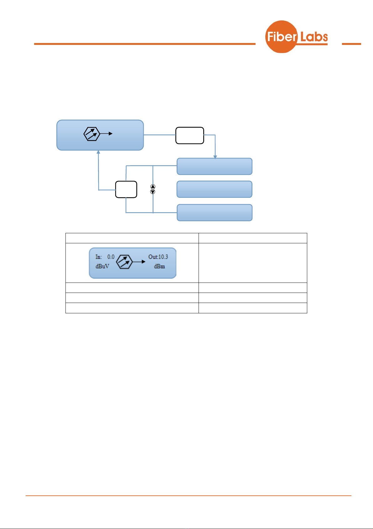
3.4.1 Main Menu
In: 0.0 Out:10.3
dBuV dBm Enter
1. Disp Parameters
2.Set Parameters
3.Alarm Status
ESC
Displayed parameters Comments
Boot display
1.Disp Parameters Menu one: Display parameters
2.Set Parameters Menu two: Set parameters
3.Alarm Status Menu three: Alarm status
Technical passport / OTM-1550
12-2016-v4
3.4.2 Display Menu
1.Disp Parameters Enter
Laser Power: xx.xdBm
Laser Bais: xx.xmA
Laser Temp: xx.x℃
Tec Current: -x.xxA
RF Chan NO: 1
ESC
IP : xxx.xxx.xxx.xxx
Msk: xxx.xxx.xxx.xxx
GTW: xxx.xxx.xxx.xxx
Mac: XX-XX-XX-XX-XX-XX
SofteWare Ver: VX.X
RF Control Mode: AGC
AGC Ref: xdB
Laser RF: x dBuV
RF Ctrl Mode: MGC
MGC ATT: XdB
Wave Length: xxxx.xnm
+5V Read: x.xxV
BOX Temp: xx.x℃
S/N: xxxx.xx.xx
-5V Read: -x.xxV
+24V Read: xx.xxV
Input Power: -xx.xdBm
OP After ATT: xx.xdBm

Technical passport / OTM-1550
12-2016-v4
Displayed parameters Comments
Laser Power Laser output optical power
OPAfter ATT Optical power after attenuation
(without inter-cut function, no this menu)
Input Power External optical signal power
(without inter-cut function, no this menu)
Laser Bais Laser bias current
Laser Temp Laser temperature
Tec Current Cooler current
RF Chan NO Channel number
Laser RF Laser RF power
RF Ctrl Mode RF control mode
MGC ATT MGC attenuation (in MGC mode)
AGC Ref AGC deviator (in AGC mode)
Wave Length Wavelength
+5V Read +5V monitoring voltage
-5V Read -5V monitoring voltage
+24V Read +24V monitoring voltage
S/N Serial number
BOX Temp Temperature
IP IP
Msk Subnet mask
GTW Gateway
Mac MAC address
SofteWare Ver Version number

Technical passport / OTM-1550
12-2016-v4
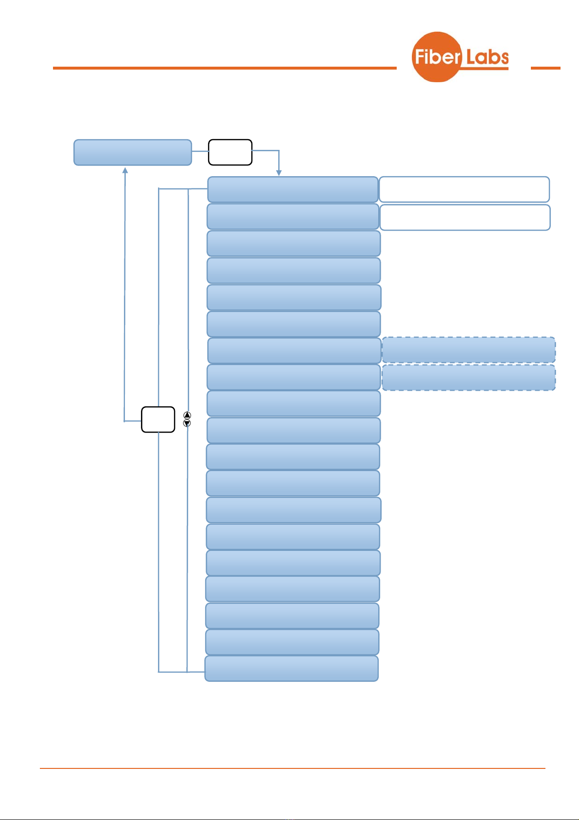
3.4.3 Set Menu
2.Set Parameters Enter
Set Buzzer Alarm
Set RF Control Mode
Set MGC ATT
Set AGC Ref
Set Local IP Address
ESC
YES NO
AGC MGC
0dB
xdBm
Set SubNet Mask
Set GateWay
xxx.xxx.xxx.xxx
Restore Factory
Set LaserOutPut Unit mW dbm
Set PredATT Mode Auto Manu
Set FiberC Length 0Km
Set Channel Number x
xxx.xxx.xxx.xxx
YES NO
Set OPT ATT Mode
+ Auto Manu
Set OPT ATT 0dB
Set OPT Delta
0dB
xxx.xxx.xxx.xxx

Technical passport / OTM-1550
12-2016-v4
Displayed parameters Comments Remarks
Set LaserOutPut Unit Set the unit of output optical
power
Set Buzzer Alarm Set the buzzer alarm YES is on, NO is off
Set RF Control Mode Set the RF control mode AGC and MGC two modes selectable
Set MGC ATT Set the ATT in MGC mode Adjustable range 0~20dB
Set AGC Ref Set the deviator in AGC mode Adjustable range ±3dB
Set PredATT Mode Set the predistortion control
mode
Two modes:
Auto is automatic control mode; Manu is
manual control mode.
Set FiberC Length Set the transmission distance in
automatic control mode 1km stepping
Set Channel Number Set the channel number
Set Local IP Address Set the IP address
Set SubNet Mask Set the subnet mask
Set GateWay Set the gateway
Restore Factory Restore factory settings
Set OPT ATT Mode Set the optical power ATT
mode Without inter-cut function, no this menu
Set OPTATT Set the optical power
attenuation Without inter-cut function, no this menu
Set OPT Delta
Set the difference between the
main optical power and the
inserted optical power
Without inter-cut function, no this menu
3.4.4 Alarm Menu
The displayed alarm content Comment
RF Alarm RF alarm
Laser Temp Laser temperature alarm
Laser Bais Laser bias current alarm
Laser Tec Laser cooling current alarm
Output Alarm Output optical power alarm
+5V Alarm +5V alarm
-5V Alarm -5V alarm
+24V Alarm +24V alarm

Technical passport / OTM-1550
12-2016-v4
4. Installing the OTM-1550L Optical Transmitter
4.1 Receiving and Inspecting
As you unpack your unit, inspect the shipping container and equipment for damage.
Save the shipping material for future use. If the container or the equipment is
damaged, notify both the freight carrier and us.
CAUTION: To protect yourself from potential injury and to protect
the equipment from further damage, do not perform any
operational tests if the equipment appears to be damaged.
4.2 Precautions
Heed the following precautions when working with the OTM-1550L.
Warning
Read the installation instructions before connecting the
system to the power source.
Warning
The plug-socket combination must be accessible at all
times, because it serves as the main disconnecting device.
4.3 Mounting OTM-1550L
4.3.1 Mounting the OTM-1550Lin the Rack
Mounting the OTM-1550L in the standard 19 inch equipment rack:
1. Place the equipment in the rack.
2. Use four screws fixed the mounting lug on the OTM-1550L front panel to the rack.
3. Reliably ground the equipment. The ground terminal is on the rear panel.
4. Visually inspect each key (button) on the front panel to ensure that it is not trapped
under the edge of its hole. If a key is trapped, tap the key to enable it to move freely.

Technical passport / OTM-1550
12-2016-v4
4.3.2 Connecting the RF Cables
Verify the RF input F connector type according to the ordering information, then
screw on the matched RF cable.
4.3.3 Connecting the Optical Fiber Cables
OTM-1550L has one or two optical connectors.
DANGER: The fiber carries invisible laser radiation. AVOID
DIRECT EXPOSURE TO BEAM. Never operate the unit with a
broken fiber or with a fiber connector disconnected.
1. Verify the matched OTM-1550L fiber cable connector type according to the
ordering information.
2. Verify that the fiber cable connector has been cleaned properly. If the fiber cable
connector needs to be cleaned, follow the cleaning procedure outlined in “Cleaning
Patch Cord or Pigtail Fiber Optical Connectors”.
3. Verify that the OTM-1550L optical connector has not been exposed to any
contamination.
NOTE: Any contamination of optical connector can significantly
degrade optical link performance. This degradation will most likely
manifest itself as poor signal-to-noise (SNR) performance.
4. Note to butt the nick of the connectors and align them accordingly.
4.3.4 Connecting the Ethernet Cable
You can connect the OTM-1550L to your TCP/IP network in order to monitor and
control the transmitter remotely. After you complete the installation procedures
described in this chapter, you can use a network management system (NMS) to
monitor and control the OTM-1550L.
To connect the OTM-1550L, you must use a shielded and grounded Category 5
Ethernet cable.
To connect the Ethernet cable:
1. Connect an Ethernet cable to the transmitter’s RJ-45 Ethernet port. The Ethernet
port is on the rear panel of the transmitter.
2. Verify that the green Link LED is illuminated, indicating that there is a connection.

Technical passport / OTM-1550
12-2016-v4
4.3.5 Connecting Power
The OTM-1550L is available in an AC220V power model. After mounting the
OTM-1550L in a rack, follow the power connection procedure below for the model
that you are installing.
Can be equipped with two 220V power supply that requires input voltage 150~
265VAC, at 50~60Hz single phase. The AC power plug is located on the rear panel.
Turn on the power source. It takes about 60 seconds for all systems to operate.
5. Communication Setup
5.1 RS232 Communication Interface Description
Adopt DB9 standard connector, the pin definitions as follow:
1: No Connect
2: TX
3: RX
4: No Connect
5: GND
6: No Connect
7: No Connect
8: No Connect
9: No Connect
The serial communication uses the standard NRZ form, 1 starts bit, 8 data bits, 1
stop bit and the baud rate is 38400.
5.2 Set up the Hyper Terminal
If you have not setup the Hyper Terminal in your Windows system, follow the steps:
Click “start menu programaccessorycommunicationHyper Terminal”:

Technical passport / OTM-1550
12-2016-v4
This results in the following screen:
Then you input your connection name, such as “SNMP38400”,and choose the serial
port to connect with your equipment. As follows:
Press the “OK” button shows the configuration page of serial port. As follows:
Change the serial port configuration to 38400-baud rate, 8 data bits, no parity bit, 1
stop bit, no data flow control, press the “OK” button, you have set up the Windows
serial port Hyper Terminal.
Technical passport / OTM-1550
12-2016-v4
You can click “filesave” menu to save this configuration of Hyper Terminal for
later using.
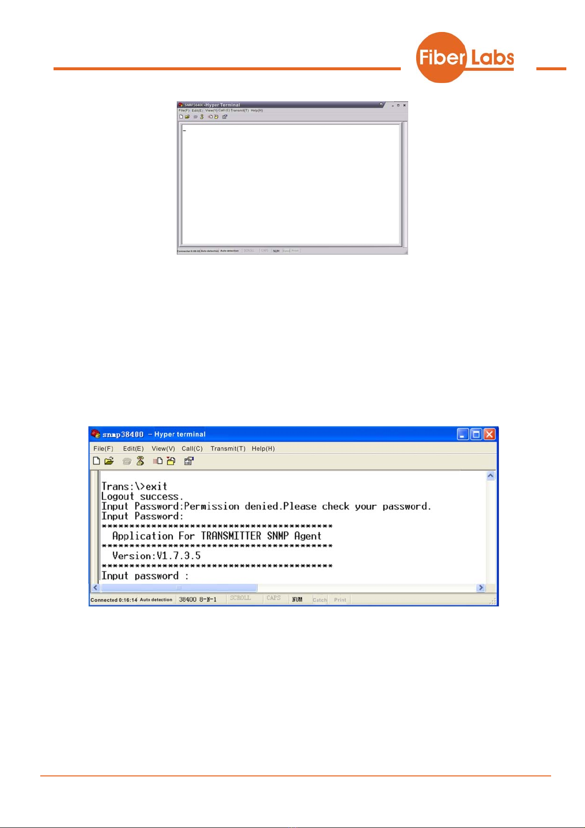
5.3 Operating Parameters Configuration
Under the condition of power off, use the serial port lines to connect the RS232 port
with the computer port. Open the Windows Hyper Terminal which you have set up.
Then turn on the power, you will see the page as follows. Enter the password to enter
the configuration interface.

Technical passport / OTM-1550
12-2016-v4
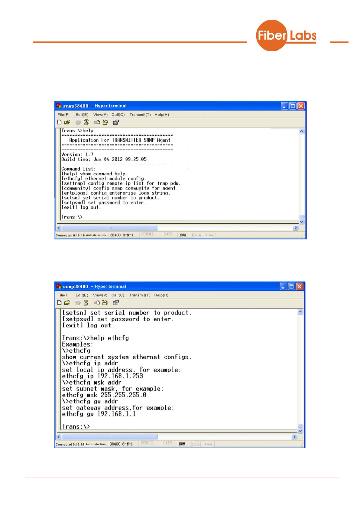
Enter the password, display the following screen:
You can input your command in this page, and then configure the operating parameter
supports the f
y
e
ogo
xit
f the SNMPTrap;
ult values;
go and equipment model;
Log out.
of the application program.
System ollowing commands:
help List internal commands of the system;
Configure the Ethernet operating parameters;
Configure the aim host IPaddress o
Configure the SNMPgroup name;
Restore the factory defa
Set the serial number;
Set the login password;
Set the lo
ethcfg
settrap
communit
Restor
setsn
setpswd
entpl
E
Technical passport / OTM-1550
12-2016-v4
Specific using as follows:
am version, program name and the
internal commands list of the system as follows:
help
This command shows current application progr
You can also use the “help” command to show help information of other commands,
such as “help ethcfg”,ethcfg’s help inform appears as follows:
ation
ethcfg

Technical passport / OTM-1550
12-2016-v4
This command configures the Ethernet parameters, including IP address, subnet mask
nd gateway. You can refer to the help information for its using.
and 255.255.255.255 don’t exist. SNMP Trap does not send to
ese two addresses.
only and read-write are both “public” as the
quipment default setting from factory.
his command is used to modify the login password.
his command is used to set the logo and equipment model.
his command is used to log out.
a
settrap
This command shows or modifies the aim host IP address list of the SNMP Trap,
IP address of 0.0.0.0
th
community
This command configures the read-only group name and read-write group name.
“Group name” is the concept of SNMP agreement like the password. Use the
command “community ro” to configure the read-only, and “community rw” for the
read-write. For example, input “community rw public”, “public” is the read-write
group name. The group name for read-
e
setpswd
T
entplogo
T
Exit
T
Table of contents
Other FiberLabs Transmitter manuals


