sauermann Si-C320 User manual


Table of contents
1. Safety instructions.................................................................................................................................................. 5
1.1 Warnings.......................................................................................................................................................... 5
1.2 Environment protection .................................................................................................................................... 5
1.3 Symbols used ................................................................................................................................................... 5
2. Conformity and standard ....................................................................................................................................... 6
2.1 FCC rules ......................................................................................................................................................... 6
2.2 Canadian standard........................................................................................................................................... 6
3. Introduction ........................................................................................................................................................... 7
3.1 Description of the transmitter ........................................................................................................................... 7
3.1.1 Overall description.................................................................................................................................... 7
3.1.2 Screen description .................................................................................................................................... 7
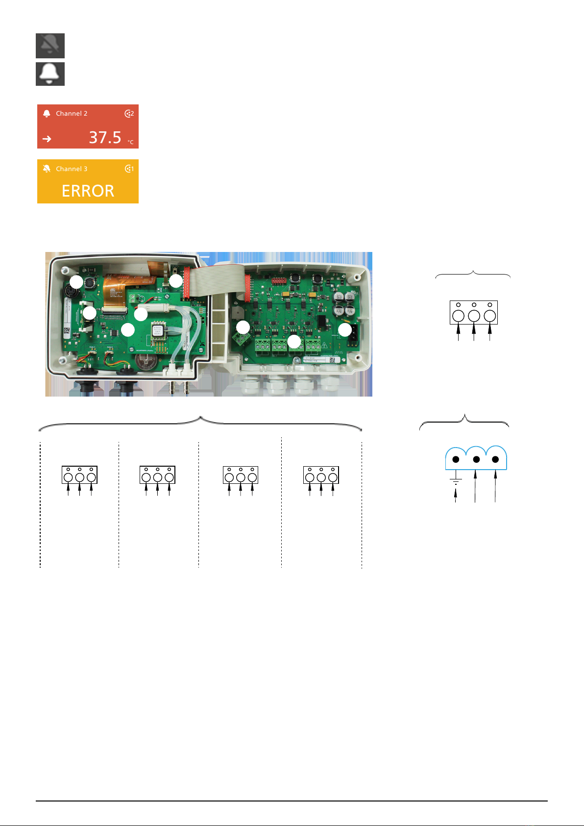
3.2 Connections..................................................................................................................................................... 8
4. Mounting ............................................................................................................................................................... 9
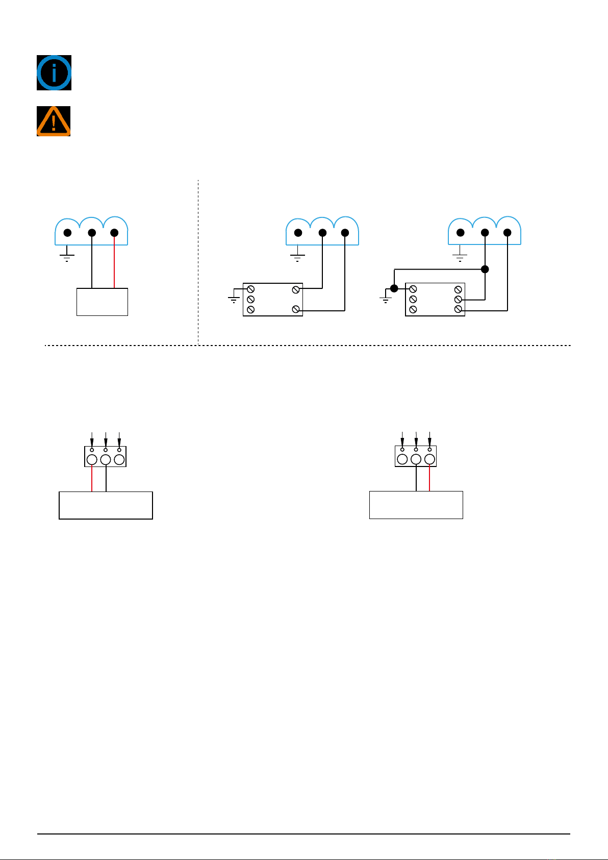
5. Electrical connections........................................................................................................................................... 10
6. First Start-up ........................................................................................................................................................ 11
6.1 Set the transmitter ......................................................................................................................................... 11
6.2 Connect a probe............................................................................................................................................. 12
6.3 Set a channel ................................................................................................................................................. 12
6.4 Set an output ................................................................................................................................................. 13
6.5 Disconnect a probe......................................................................................................................................... 13
7. Transmitter features ............................................................................................................................................. 14
7.1 General features............................................................................................................................................. 14
7.2 Features of the housing .................................................................................................................................. 14
7.3 Dimensions .................................................................................................................................................... 15
7.4 Possible optional measurements ..................................................................................................................... 15
8. Set the transmitter ............................................................................................................................................... 16
8.1 Set the language............................................................................................................................................ 16
8.2 Set the country............................................................................................................................................... 16
8.3 Set the date, time zone and time .................................................................................................................... 16
8.4 Set the brightness .......................................................................................................................................... 16
9. Set inputs and outputs......................................................................................................................................... 17
9.1 Set the measurement channels ....................................................................................................................... 17
9.2 Set the outputs............................................................................................................................................... 17
9.2.1 Set the analog outputs ........................................................................................................................... 17
9.2.2 Perform an output diagnostic.................................................................................................................. 18
9.2.3 Set the digital output (Modbus RTU) ....................................................................................................... 19
9.3 Set the probes and modules ........................................................................................................................... 19
9.3.1 Normative values.................................................................................................................................... 19
9.3.2 Congure the compensation of a CO2or hygrometry probe ..................................................................... 19
9.3.3 Congure a differential pressure module................................................................................................. 20
9.4 Set the alarms................................................................................................................................................ 22
9.4.1 Set the alarm thresholds......................................................................................................................... 22
9.4.2 Set the alarms parameters ...................................................................................................................... 22
9.5 Set the autozero............................................................................................................................................. 23
9.6 Set the relays (optional).................................................................................................................................. 23
10. Security and connectivity ................................................................................................................................... 25
10.1 Wireless communication ............................................................................................................................... 25
10.2 Dene the security code ............................................................................................................................... 25
10.3 Dene the Touch Lock functionality............................................................................................................... 25
10.4 Reset instrument from factory....................................................................................................................... 25
11. Information about transmitter, probes and modules .......................................................................................... 27

11.1 Instrument and probes/modules information ................................................................................................. 27
11.2 Adjustment and calibration information ........................................................................................................ 27
11.3 Probe update ............................................................................................................................................... 27
12. Modbus.............................................................................................................................................................. 28
12.1 Conguration of parameters......................................................................................................................... 28
12.2 Functions ..................................................................................................................................................... 28
12.3 Data format ................................................................................................................................................. 28
12.4 Description of function and Modbus connections .......................................................................................... 28
12.4.1 Device.................................................................................................................................................. 28
12.4.2 Channels.............................................................................................................................................. 29
12.4.3 Outputs................................................................................................................................................ 30
12.4.4 Alarms ................................................................................................................................................. 30
12.4.5 Probes and module parameters............................................................................................................. 31
12.4.6 Normative values.................................................................................................................................. 35
12.4.7 Alarms ................................................................................................................................................. 35
13. Maintenance and precautions for use................................................................................................................ 36
13.1 Maintenance................................................................................................................................................ 36
13.2 Precautions for use....................................................................................................................................... 36

Safety instructions 5
1. Safety instructions
Before using the device, please read carefully this user manual. It delivers important information about the device
operations, maintenance and storage.
1.1 Warnings
• Interior use.
• Respect the measuring ranges of the probes and modules connected to the transmitter.
• This device has been developed to measure simultaneous parameters including differential pressure, temperature
(Pt100 and thermocouple), hygrometry, air quality (CO/CO2/VOC), air velocity, airow, air change rate. It must not
be used in any other purpose.
• This device has been developed and produced to be sold exclusively to trained and qualied HVACR technicians
and engineers. Appropriate training might be necessary in order to ensure safe use of this instrument. Sauermann
is not responsible for any possible accident during its use.
• Please always use the device in accordance with its intended use and within parameters described in the technical
features in order not to compromise the protection ensured by the device.
• When using the device, the safety of the system integrating the device is the responsibility of the system assembler.
• This device can pose a risk for pacemaker wearers. Respect a distance of at least 10 cm (4") between the device
and the wearer.
• Respect a safety distance with other electronic devices like computers, credit cards, computer or TV screens which
could be damaged by the magnetic eld of the apparel.
• Only the accessories provided with the device or available as an option must be used.
• Do not use the device if it is damaged or if it operates abnormally. Inspect the device before every use. In case of
doubt, please contact Sauermann’s After-sales service.
• Do not authorize pressures beyond the device limits. Please refer to the technical features described in this user
manual.
• The device must not be exposed to rain or any other humid environments (> 85 %RH) without using a proper
protection.
• Do not use the device next to explosive and corrosives gases, vapours or dust.
• Do not place your ngers in movable zones of the device (articulations).
• The device must not be used in ATEX zones according to applicable standards.
• Do not store the device with solvents. Do not use desiccants. Do not use isopropanol.
• During use, keep inspecting the device and accessories for effective operation and your own safety.
• Do not give this product to a child.
• If the device falls or in case of similar inconveniences, or if an irregular malfunction appears, please send back the
device to Sauermann's After-sales service for a technical check and to ensure your own safety.
1.2 Environment protection
Send back the device at its end of working life for waste collection center of electrical and electronic components
(according to local regulations), or send it back to Sauermann to ensure a required waste collection in the respect of
the environment.
1.3 Symbols used
For your safety and in order to avoid any damage of the device, please follow the procedure described in this user
manual and read carefully the notes preceded by the following symbol:
The following symbol will also be used in this user manual:
Please read carefully the information notes indicated after this symbol.
© 2023 SAUERMANN. All rights reserved. Sauermann and Sauermann Control App are the exclusive property of Sauermann. Non contrac-
tual document. The products functionalities and visual appearances can be modied without prior notice. Smartphone or tablet are not
supplied with Sauermann products.

6 Conformity and standard
2. Conformity and standard
The transmitter complies with 2015/863 EU (RoHS 3). Document available on request.
Hereby, Sauermann Industrie SAS declares that the radio equipment type Si-C320 is in compliance with Directive
2014/53/EU. The full text of the EU declaration of conformity is available at the following internet address:
sauermanngroup.com.
2.1 FCC rules
This equipment has been tested and found to comply with the limits for a Class B digital device, pursuant to part
15 of the FCC Rules. These limits are designed to provide reasonable protection against harmful interference in a
residential installation. This equipment generates, uses and can radiate radio frequency energy and, if not installed
and used in accordance with the instructions, may cause harmful interference to radio communications. However,
there is no guarantee that interference will not occur in a particular installation. If this equipment does cause harmful
interference to radio or television reception, which can be determined by turning the equipment off and on, the user
is encouraged to try to correct the interference's by one or more of the following measures:
• Reorient or relocate the receiving antenna.
• Increase the separation between the equipment and receiver.
• Connect the equipment into an outlet on a circuit different from that to which the receiver is connected
• Consult the dealer or an experienced radio/TV technician for help.
Changes or modications not expressly approved by Sauermann could voice the user’s authority to operate the
equipment.
This device complies with part 15 of the FCC Rules.
Operation is subject to the following two conditions:
1. This device may not cause interference, and
2. This device must accept any interference received, including interference that may cause undesired operation.
2.2 Canadian standard
This device contains licence-exempt transmitter(s)/receiver(s) that comply with innovation, Science and Economic
Development Canada’s licence-exempt RSS(s). Operation is subject to the following two conditions:
1. This device may not cause interference
2. This device must accept any interference, including interference that may cause undesired operation of the device.

Introduction 7
3. Introduction
3.1 Description of the transmitter
3.1.1 Overall description
3
4
5
6
7
8
9
1
1 - Touch screen
2 - Access to device settings menu
3 - Transmitter power indicator
4 - Pressure connection
5 - Pressure connection
6 - Cable glands
7 - Probe connection 1
8 - Probe connection 2
9 - Wireless connection light
10 - Access to Graph view
102
3.1.2 Screen description
2
1
3
4 5
61. Channel ID
2. Alarm pictogram
3. Trend indicator
4. Measured value
5. Unit of the measured value
6. Source probe for the channel
Trend indicator:Trend indicator: on the screen, a trend indicator represented by a rising arrow, a going down arrow or a stable ar-
row is displayed on the left of the measurement unit. It means the calculation of a moving average on the last hour
(M1) to compare with a moving average on the last 5 minutes (M2):
• If M1 = M2, the trend is stable.
• If M1 < M2, the trend is upwards.
• If M1 > M2, the trend is downward.
This trend indicator is displayed after 5 minutes.
Alarm pictogram: on the screen, an alarm pictogram is displayed for each channel. Two different pictograms can
be displayed:

8 Introduction
There is no alarm congured and activated for the channel
An alarm is congured and activated for the channel
Channel 2
2
37.5
°C
In case of alarm, the measurement concerned by the alarm will be in red on the screen
Channel 3
ERROR
1
In case of faulty communication with the transmitter, the concerned channel's background
will change to orange. By tapping on the screen a message with additional information
about the problem is displayed.
3.2 Connections
Analog output 3
(OUT 3)
Analog output 4
(OUT 4)
Analog output 1
(OUT 1)
Analog output 2
(OUT 2)
(b)
24 VDC/VAC power supply:
(c)
Phase (L) +
Neutral (N) -
Operational grounding
COM
0/4-20 mA – Current
0-5/10 V – Voltage
COM
0/4-20 mA – Current
0-5/10 V – Voltage
COM
0/4-20 mA – Current
0-5/10 V – Voltage
COM
0/4-20 mA – Current
0-5/10 V – Voltage
RS-485 interface
(a)
B-
A+
0 V
1
2
3
4
5
6
7
8
1 - Connection for PC software
2 - Wireless module (optional)
3 - Pressure module (optional)
4 - Solenoid valve
5 - Autozero
6 - RS-485 connection (a)
7 - Analog outputs (b)
8 - Power supply terminal block (c)

Mounting 9
4. Mounting
The transmitter must be mounted before any wire connections.
The transmitter must not be powered before mounting it.
To install the transmitter on a wall:
• Fix the stainless steel plate to the wall (drilling: Ø 8 mm, screws and wall-plugs supplied).
• Insert the transmitter on the plate (see A on the drawing below) by aligning it at 30°.
• Rotate the housing in clockwise direction until you heard a “click” which conrms that the transmitter is cor-
rectly installed.
• Open the housing, lock the clamping system of the housing on the plate with the screw (see photo below).
The xing screw is in a plastic bag into the box of the C320. type of screw: Cruciform screw Ø 3.5x12 mm
A
A
120 mm (4.73’’)
Ø 5,4 mm (0.21’’)
65 mm (2.56’’)
65 mm (2.56’’)
98 mm (3.86’’)
To remove the transmitter from the xing plate, do not forget to remove this screw.
Fixing screw of the housing

10 Electrical connections
5. Electrical connections
Electrical connections are as per NF C 15-100 standard.
This connection must be made by a trained and qualied technician. Whilst making the connec-
tion, the transmitter must not be energized. The presence of a switch or a circuit breaker up-
stream the device is compulsory.
-
+
-+
24 VDC
power supply
NL
Pe
N
L
240 VAC
N
L
24 VAC power supply
Class II
NL
Pe
N
L
240 VAC L
24 VAC power supply
or
N
COM
0/4-20 mA
0-5/10 V
-+
Regulator display or
PLC/BMS (passive type)
COM
0/4-20 mA
0-5/10 V
-+
Regulator display or
PLC/BMS (passive type)
For 24 VDC models: For 24 VAC models using power supply converters:
0/4-20 mA current output connection: 0-5/10 V voltage output connection:

First Start-up 11
6. First Start-up
When the transmitter is rst started up, parameters of the transmitter must be set.
6.1 Set the transmitter
Select Date
11
11
DAY
MONTH
YEAR
01
2021
/
/
MONTH / DAY / YEAR
DAY / MONTH / YEAR
Next
Set your Time Zone
+1
DAY
MINUTES
0
Next
:
• Los Angeles: -8 winter, -7 summer
• New York: -5 winter, -4 summer
• London: +0 winter, +1 summer
• Paris: +1 winter, +2 summer
• Dubai: +4 • Beijing: +8 • Tokyo: +9
• Sydney: +10 winter, +11 summer
10:35 - 10/12/2021
Set your time
+1
DAY
MINUTES
0
0
Next
:
24 hours
AM
PM
10:35 - 10/12/2021
Please connect the probe(s)
before conguring the
channel(s)
Channel Conguration
10:35 - 10/12/2021
Next
Model: XXXXX - S/N: XXXXXX - Build: XXXXXXX - FMW:
XXXXX - Version: 5.02
Start Settings
Welcome
Skip
Languages
Next
English
German
Portuguese
Spanish
Chinese
Italian
French
Tap ‘’Start settings’’.Select your language
and tap ‘’Next’’.
Tap your continent.Tap your area.
Set the date and tap ‘’Next’’.Set your time zone and tap
‘’Next’’.Set your time and
tap ‘’Next’’.
The transmitter is set. You can
connect a probe to set a channel.
Select Continent
Africa
APAC
North America
LATAM
Europe
Northern
Rest of Europe
Southern
Middle East
Western
Europe
Netherlands
Austria
Belgium
Germany
Western
Switzerland
France
Tap your required
country then ‘’Next’’.
Next
For models without display, please use the app to set your transmitter.
Download Sauermann Control App

12 First Start-up
6.2 Connect a probe
• After removing the protection cap on the transmitter connector, present the probe connector (a) with its arrow
and padlock face to the transmitter connector (b).
• Push in the probe connector (a) into the transmitter connector (b) until you hear a click. The probe is correctly
connected.
CLICK
a
b
6.3 Set a channel
Please connect the probe(s)
before conguring the
channel(s)
Channel Conguration
10:35 - 10/12/2021
Next
Connect a probe to set a
channel and tap ‘’Next’’.
Channel 1
Channel 3
Channel 4
Channel 2
10:35 - 10/12/2021
Select Channel
Next
The list of available channel is
displayed.
Tap the required channel.
Select Channels
10:35 - 10/12/2021
Channel 1
Channel 3
Channel 4
Channel 2
Next
Tap ‘’PROBE 1’’, ‘’PROBE
2’’ or ‘’MODULE’’.
Parameters to set are now
available.
10:35 - 10/12/2021
Channel 2
Units
- - - -
Coefcient
Measures
SELECT UNIT
PROBE 1
PROBE 2
MODULE
Offset
Activate the channel taping .
‘’Measures’’, ‘’Units’’, ‘’Coefcient’’ and
‘’Offset’’ are now available.
Set the parameters according
to your needs then tap the
back arrow on the top left.
10:35 - 10/12/2021
Units
Coefcient
Measures
Rel. Humidity
PROBE 1
PROBE 2
MODULE
Channel 2
Offset
%RH
1.000
0.00
Channel 1
Channel 3
Channel 4
Channel 2
10:35 - 10/12/2021
Select Channel
Next
Next
Channel 2 is congured. Tap
next to congure outputs.
1.000
0.00
For models without display, please use the app to set your channel.
Download Sauermann Control App

First Start-up 13
6.4 Set an output
Tap the output to set corres-
ponding to the previously
congured channel.
Tap ‘’Next’’ to
display measures.
Next
Output 2
10:35 - 10/12/2021
Select Analog Output
Output 3
Diagnostic
10:35 - 10/12/2021
Output 2
4-20 mA
Output type
High Range (%RH)
Low Range (%RH)
98.0
10.0
Activate the output taping .
Set the output type and high
and low range values then tap
the back arrow on the top left.
Output 1
Output 4
Next
Output 2
10:35 - 10/12/2021
Select Analog Output
Output 3
Output 1
Output 4
Next
10:35 - 10/12/2021
Measures
Channel 2
1
27.7
%RH
For models without display, please use the app to set your output.
Download Sauermann Control App
6.5 Disconnect a probe
• Turn the ring (c) of the probe connector to the left.
• Pull the probe connector (a) away from the transmitter connector (b).
c
ab

14 Transmitter features
7. Transmitter features
7.1 General features
Power supply
24 VAC / VDC ±10%
Warning: risk of electric shock
Outputs
4 x 4-20 mA, 0-20 mA, 0-10 V or 0-5 V analogue outputs
Common mode voltage <30 VAC
Maximum load: 500 Ω (0/4-20 mA)
Minimum load: 1 KΩ (0-5/10 V)
Galvanic isolation
Inputs (power supply) and outputs
Device fully protected by
DOUBLE ISOLATION or REINFORCED ISOLATION
Consumption with
probe and without
option
15 VA
Electrical connec-
tions
Screw terminal block for cables from 0.05 to 2.5 mm2or from 30 to 14 AWG
Carried out according to the code of good practices
RS485 communica-
tion Modbus RTU protocol, congurable communication speed from 2400 to 115200
Wireless communi-
cation (option)
Range frequency from 2402 MHz to 2480 MHz with a transmission power of 0 dBm.
Range up to 15 m (50 ft), depending on smartphone radio strength.
Minimum required versions: Android 5.0, iOS 12.4, BLE 4.0
Audible alarm Buzzer (60 dB at 10 cm)
Environment and
type of uid Air and neutral gases
Conditions of use
(°C/%RH/m)
From -10 to 50 °C (14 to 122 °F)
In non-condensing environment
From 0 to 2000 m (0 to 6562 feet)
Storage
temperature From -10 to 70 °C (14 to 158 °F)
Security Protection class 2 - Pollution degree 2 - Overvoltage category 2
European directives 2014/30/EU EMC - 2014/35/EU Low Voltage - 2014/53/EU (RED) -
2015/863 EU (RoHS 3) - 2012/19/EU WEEE
7.2 Features of the housing
Material ABS V0 as per UL94
Protection IP66, resistant to VHP
Display (optional) Color Touch Screen with graphing
Size: 480 x 272 pixels
Cable gland In polycarbonate for cables from Ø 4.5 to 8 mm
(Ø 0.18’’ to 0.32’’)
Weight 626 g (1.4 lb)

Transmitter features 15
7.3 Dimensions
158.25 mm (6.23’’)
135.80 mm (5.35’’)
10 mm
(0.39’’)
30 mm
(1.18’’)
13 mm (0.51’’)
47.55 mm
(1.87’’)
35 mm (1.38’’)
76.65 mm (3.02’’)
7.4 Possible optional measurements
The following probes and modules are available as an option for Si-C320 transmitters. For further details please see
the probes technical data sheet for class 320 transmitters.
Probes / modules Measuring ranges Calculated parameters
Differential pressure
module (with terminal
block for K thermo-
couple probe)
Available ranges from -50/50 Pa to
-10000/10000 Pa (-0.2/0.2 inH2O to -40 to
40inH2O)
(according to the module)
-200 to 1300°C (-328 to 2372 °F)
(depending on the connected probe)
Air velocity: up to 100 m/s (0 to 328 fps)
Air ow: 0 to 999,999 m³/h (0 to 588,577cfm)
Air change rate: 0 to 1000 ACH
Relative humidity /
temperature probe
0 to 100 %RH and -40 to 150 °C (-40 to
302 °F) (according to the probe)
Dew point: -50 to 100 °Ctd (-58 to 212 °Ftd)
Wet-bulb temperature: -50 to 100 °Ctw (-58 to 212 °Ftw)
Frost point: -50 to 100 °Ctf (-58 to 212 °Ftf)
Enthalpy: 0 to 15,000 kJ/kg
Absolute humidity: 0 to 1000 g/m³
Mixing Ratio: 0 to 1000 g/kg
Temperature probe -80 to 150 °C (-112 to 302 °F) N/A
Air velocity / temper-
ature probe
0 to 30 m/s (0 to 98.4 fps) and 0 to 50 °C
(32 to 122 °F)
Air ow: 0 to 999,999 m³/h (0 to 588,577cfm)
Air change rate: 0 to 1000 ACH
CO probe 0 to 500 ppm N/A
CO2probe 0 to 10,000 ppm N/A
VOC probe TVOC: 0 to 1000 ppb
CO2eq: 400 to 2000 ppm N/A

16 Set the transmitter
8. Set the transmitter
"Device Settings" menu allows to set the following items for the transmitter:
• Language
• Country
• Date, time and time zone
• Brightness
To access to this menu:
• Tap on the measurement screen.
• Enter the security code.
Default security code is 0101. This code can be modied in "Security/Connectivity" menu. See chapter 9.2
on page 25.
• Tap "Device Settings".
8.1 Set the language
"Device settings" menu is displayed.
• Tap "Languages".
• Tap the requested language.
Available languages: English, French, Spanish, Italian, German, Portuguese and Chinese.
8.2 Set the country
"Device settings" menu is displayed.
• Tap "Country".
• Select the continent.
• Select the country.
8.3 Set the date, time zone and time
"Device settings" menu is displayed.
• Tap "Date, Time Zone, ...".
• Tap "Date", "Time" or "Time zone" depending on the settings to be made.
• Perform the settings.
8.4 Set the brightness
"Device settings" menu is displayed.
• Tap "Brightness".
• Adjust the brightness of the screen from 1 to 5.
• Tap the back arrow on the top left of the screen to back to "Device Settings" menu.

Set inputs and outputs 17
9. Set inputs and outputs
"I/O Congurations" menu allows to set the following items:
• Channels: activate and set the probes and modules connected to the transmitter
• Outputs: activate and set outputs corresponding to the channels
• Probes and Modules: dene normative values according to probes and modules connected to the transmitter and
dene some parameters linked to probes and modules
• Alarms: activate and set alarm features
• Autozero: activate and set the autozero interval
To access this menu:
• Tap on the measurement screen.
• Tap the security code.
Default security code is 0101. This code can be modied in "Security/Connectivity" menu. See chapter 9.2
on page 25.
• Tap "I/O Congurations".
9.1 Set the measurement channels
At least one probe or one differential pressure module must be connected to the transmitter.
"I/O Congurations" menu is displayed.
• Tap "Channels".
• Tap the desired channel number (Channel 1, 2, 3 or 4).
Features of the channel are displayed.
• Tap “PROBE 1”, “PROBE 2” or “MODULE” according to the required attribution for the channel.
"Measures" becomes available.
• Tap "Measures".
• Select the required parameter then tap the back arrow on the top left of the screen.
• Tap "Units".
• Select the required measurement unit then tap the back arrow on the top left of the screen.
The channel is automatically activated (toggle switch is on).
• If required, enter a coefcient and an offset to the channel.
• Tap the back arrow on the top left of the screen until measurement screen is displayed.
"Values measured by the probe or the module are displayed.
Special case: two units are available for the VOC probe: ppb and ppm CO2equivalent. If ppm is
selected, the transmitter will take 15 minutes to display the rst measurements (pre-heating
phase).
The channel name can be changed:
• Tap next to the channel name to edit it.
• Enter a name. Maximum characters: 13.
• Tap OK to validate.
9.2 Set the outputs
Two types of outputs are available: analog outputs and digital outputs
9.2.1 Set the analog outputs
At least one measurement channel must be congured.
If no channel has been congured, no analog output will be delivered.

18 Set inputs and outputs
"I/O Congurations" menu is displayed.
• Tap "Outputs".
• Tap "Analog Outputs".
• Tap the desired output (Output 1, 2, 3 or 4 depending on the number of the previously congured channel).
Features of the output are displayed.
• Tap on the top right of the screen to activate the output
• Tap "Output type".
• Select the output type: 0-5 V, 0-10 V, 0-20 mA or 4-20 mA then tap the back arrow on the top left of the screen.
• Tap "High range".
• Dene the high range value for the output then tap the back arrow on the top left of the screen.
• Tap "Low range".
• Dene the low range value for the output then tap the back arrow on the top left of the screen.
9.2.2 Perform an output diagnostic
This function allows to check on a measurement device (multimeter, regulator or automate) the proper functioning
of the outputs. The transmitter will generate a voltage (between 0 and 10 V) or a current (between 0 and 20 mA)
according to the setting of the type of output.
• For a 0-10 V output signal, the transmitter will generate 0 – 5 or 10 V.
• For a 0-5 V output signal, the transmitter will generate 0 – 2.5 or 5 V.
• For a 4-20 mA output signal, the transmitter will generate 4 – 12 or 20 mA.
• For a 0-20 mA output signal, the transmitter will generate 0 – 10 or 20 mA.
Before carrying out the output diagnostics, all connections and congurations of the transmitter
must be enabled, to avoid any damage on the transmitter and the measurement device.
• Select a channel for the outputs diagnostic.
OUT1, OUT2, OUT3 or OUT4 indicated on the electronic board above the terminal blocks.
• Connect a measurement device on the output 1, 2, 3 or 4.
Once the connection to the measurement device is complete, the output diagnostic on several check points can be
performed:
"I/O Congurations" menu is displayed.
• Tap "Outputs".
• Tap "Analog Outputs".
• Tap "Diagnostic" line.
• Tap the required value.
The values proposed will depend on the type of output previously selected. For example, if the output type
is 4-20 mA, proposed values will be 4 mA, 12 mA and 20 mA.

Set inputs and outputs 19
If the deviations are too large (> 0.05 V or > 0.05 mA) between the signal issued and the value
displayed on the multimeter, we recommend that you return the transmitter to our factory.
9.2.3 Set the digital output (Modbus RTU)
"I/O Congurations" menu is displayed.
• Tap "Outputs".
• Tap "Digital Outputs".
Features of Modbus are displayed.
• Tap "Slave address".
• Dene the slave address number between 1 and 255 then tap the back arrow on the top left of the screen.
• Tap "Baud rate".
• Select the baud rate between 2400, 4800, 9600, 19200, 38400, 57600, 76800 and 115200 then tap the back
arrow on the top left of the screen.
Default baud rate: 9600
9.3 Set the probes and modules
This menu allows to dene relevant values related to the probes and modules connected to the transmitter and de-
ne some parameters linked to them:
• For an air velocity probe (hotwire probe): duct dimensions and type of section, the correction factor, the inte-
gration in air velocity and the compensation in atmospheric pressure for airow calculation.
• For a pressure module: for air velocity and airow calculation the duct dimensions and type of section, the air-
ow coefcient, the pressure probe coefcient, the integration in pressure and autozero duration.
• For a CO2probe: the compensation in atmospheric pressure
• For an hygrometry probe: the compensation in atmospheric pressure for the psychrometry calculations
At least one probe or one module must be connected to the transmitter.
9.3.1 Normative values
For the airow calculations, it is possible to convert the value into normative values (ex: Nm³/h).
The conversion can be done according to two standards:
• DIN 1343: 1013.325 hPa, 273,15 K (0°C)
• ISO 2533: 1013.325 hPa, 288,15 K (15°C)
"I/O Congurations" menu is displayed.
• Tap "Probes & Modules".
The screen displays the connected probes and modules.
• Tap "Normative values".
• Select the normative value according to your needs: DIN 1343 or ISO 2533 then tap the back arrow on the top
left of the screen.
9.3.2 Congure the compensation of a CO2or hygrometry probe
A CO2or hygrometry probe must be connected to the transmitter.
Set the compensation in atmospheric pressure:
"I/O Congurations" menu is displayed.
• Tap "Probes & Modules".
The screen displays the connected probes and modules.
• Tap the line corresponding to the temperature/hygrometry probe or to the CO2probe.
• Tap "Atmo pressure".
• Tap "Unit" to select the atmospheric pressure unit.
• Tap "Atmo pressure" to enter a value. This value must be between:

20 Set inputs and outputs
• 0 and 4000 hPa
• 0 and 4000 mbar
• 0 and 3000.24 mmHg
• 0 and 10 000 m (altitude)
9.3.3 Congure a differential pressure module
A differential pressure module must be connected to the transmitter.
Select the measuring device:
"I/O Congurations" menu is displayed.
• Tap "Probes & Modules".
The screen displays the connected probes and modules.
• Tap the line corresponding to the pressure module.
• Tap "Device".
• Tap "Type".
• Tap the desired measurement mean between:
• Pitot tube L (coefcient: 1.0015)
• Pitot tube S (coefcient: 0.84)
• Debimo blades (coefcient: 0.8165)
• Other (free coefcient)
If "Other" is selected, the coefcient of the other measurement mean should be entered. This coefcient
must be between 0.0001 and 9.9999.
• Tap the back arrow on the left of the screen to back to conguration menu.
Select the type of duct section:
"I/O Congurations" menu is displayed.
• Tap "Probes & Modules".
The screen displays the connected probes and modules.
• Tap the line corresponding to the pressure module.
• Tap "Section".
• Tap "Shape".
• Tap the requested section:
• Rectangular
• Circular
• Custom coefcient
For a rectangular section:
• Tap "Unit" to select the unit: mm or in, then tap the back arrow on the top left of the screen.
• Enter the length and width of the section.
Length and width of the section must be between 1 and 3000 mm (0.039 to 118.11 in).
For a circular section:
• Tap "Unit" to select the unit: mm or in, then tap the back arrow on the top left of the screen.
• Enter the diameter.
Diameter of the section must be between 1 and 3000 mm (0.039 to 118.11 in).
Other manuals for Si-C320
1
Table of contents
Other sauermann Transmitter manuals