FineTek EAX30000-B User manual


Contents
1. Reading Labels.........................................................................................1
2. Product Warranty .....................................................................................2
2.1 New Product Warranty.........................................................................2
2.2 Repair Warranty...................................................................................2
2.3 Service Network...................................................................................3
3. Product Inspection...................................................................................4
3.1 Check Content.....................................................................................4
3.2 Safety Inspection .................................................................................4
4. Summary...................................................................................................4
5. Product Features......................................................................................4
6. Ordering Information................................................................................5
7. Dimensions & Wiring................................................................................6
8. Working Principles...................................................................................7
9. Specification.............................................................................................7
10. Installation .............................................................................................8
10.1 Installation precautions......................................................................8
10.2 Names of parts ..................................................................................8
10.3 Settings according to the tank............................................................9
11. Parameter Functions...........................................................................10
11.1 Operating Instructions......................................................................10
11.2 Menu Setup .....................................................................................15
11.3 Weir flowmeter setting .....................................................................17
11.4 Setting parameters...........................................................................19
12. Connection to the computer (RS485)................................................21
13. RS485 MODBUS communication format...........................................22
14. Transportation and Storage................................................................24

1
1. Reading Labels
Thanks for purchasing FineTek’s Product. This operation manual describes the product
features, working principles, operation and maintenance methods. It makes the user fully
understand how to use the product correctly, so as to prevent dangerous situations such as
device damage or operator injury.
➢Please read this operation manual completely and carefully before using the product.
➢Please contact the company if this operation manual can’t satisfy your demands.
➢The content of the operation manual is updated based on the version upgrade, which will
be uploaded to the website for the user to access.
➢Please don’t disassemble or repair the product on your own, as this will make you
disqualified from availing of the warranty service. Please send the product back to the
company for repair and calibration, or just contact the company.
➢Explanation of warning signs:
Danger→ It indicates that wrong operation will cause death or major
disasters.
Note→ It indicates that wrong operation will cause injury and device damage
to some extent.
Electric shock→ It warns of possible electric shock.
Fire→ It warns of possible fire.
Prohibited→ It indicates the prohibited wrong behavior.

2
2. Product Warranty
2.1 New Product Warranty
➢Wedon’t charge for the inspection, part/s and repair for the product of the company
that has a defect within 12 months from the delivery date and meets the warranty
terms.
➢If the product defect is not due to human error during its transportation, user may
change to a new unit from the company within 7 days from delivery date.
➢When the product needs to be sent back to the factory for repair, please send the
whole set, and don’t disassemble the parts. Moreover, please be sure it is
completely packed to avoid damage and causing more loss and defect during the
transportation.
➢The warranty is not available for causes that fall under the following circumstances,
for which the company shall charge for the inspection, part/s and repair according
to the actual condition:
⚫The product or its parts are beyond the warranty period.
⚫Fault or damage is caused by not following the instruction and use
environment described on the operation manual.
⚫The product damage is caused by a force majeure factor (natural disasters, floods,
fire, earthquakes, lightning, typhoon, etc.), human destruction (scratches, dropping,
latch broken, tapping, cracks and punching), human error (using improper voltage,
high-humidity, water leakage, stain, corrosion, loss, improper storage, etc.) and
other abnormal factors.
⚫The damage is caused by the customer or the 3rd party through the installation,
addition, expansion, modification and repair of parts not authorized or certified by
the company.
⚫The volume label information is wrongor unclear, so the product serial number can’t
be confirmed.
2.2 Repair Warranty
A 6-month warranty service is provided for the repaired part of the product, during
which the same product can be repaired free of charge in case of the same fault.

3
2.3 Service Network
Company
Address
Telephon
Fax
Taipei Headquarters
(Taiwan)
No.16, Tzuchiang St., Tucheng
Industrial Park, New Taipei City
23678
+886 2 2269 6789
+886 2 2268 6682
Taichung
Sales office
(Taiwan)
+886 4 2465 2820
+886 4 2463 9926
Kaohsiung
Sales office
(Taiwan)
+886 7 333 6968
+886 7 536 8758
Fine automation
Co., Ltd.
(China)
No. 451, Duhui Road,
Zhuanqiao Township, Minhang
District, Shanghai City 201109
+86 021 64907260
+86 021 6490 7276
Aplus FineTek
(Sensor Inc.)
355 S. Lemon Ave, Suite D,
Walnut,
CA 91789
1 909 598 2488
1 909 598 3188
FineTek Pte Ltd.
(Singapore Branch)
No. 60 Kaki Bukit Place,
#07-06 Eunos
Techpark 2 Lobby B,
Singapore 415979
+65 6452 6340
+65 6734 1878
FineTek GmbH
(Germany Branch)
Bei den Kämpen 26
21220 Seevetal-Ramelsloh,
Germany
+49 (0) 4185 8083 12
+49 (0) 4185 8083 80
FineTek Co., Ltd.
(Indonesia Branch)
Ruko Golden 8 Blok H No.38
Gading Serpong, Tangerang
Indonesia 15810
+62 (21) 2923 1688
+62 (21) 2923 1988

4
3. Product Inspection
3.1 Check Content
➢Ultrasonic Level Transmitter x1
➢Distribution cable 10m
➢Operation Manual x1
3.2 Safety Inspection
➢Please check whether the external package is deformed or damaged. Please
remember to take a picture for evidence for compensation later.
➢After unpacking, please check whether the content is deformed or damaged,
or has any quality problem. Please remember to take a picture for evidence
for compensation later.
➢After unpacking, please check whether the content is consistent with the
ordering info,
and whether the quantity is right.
➢Please contact the company within 7 days if any of the above situations occur
(attach
the picture together with your complaint). Otherwise, we won’t compensate
for, change or repair the product defect.
4. Summary
EAX is a compact, 4-wires ultrasonic level transmitter for continuous
measurement of liquids. As a price leader, it does not compromise on good
value; and provides effortless and intuitive operation. Easy and flexible
mounting combined with high chemical compatibility and 10-metre measuring
range makes the EAX suitable in multiple applications in all industries.
5. Product Features
➢4~20mA 4 wire output (Fully isolated)
➢IP65 protection
➢Transducer material: PP
➢False echo detection
➢Internal temperature compensation.
➢Not affected by liquid temperature, S.G, viscosity

5
6. Ordering Information

6
Power
Source
Lower limit
alarm relay
Upper limit
alarm relay
7. Dimensions & Wiring
Red lead wire: Power source 12-24 VDC(+)
Black lead wire: Power source 0V(-)
Yellow lead wire: Upper limit alarm SW (Open collector output, NPN type)
White lead wire: Lower limit alarm SW (Open collector output, NPN type)
Orange lead wire: RS485(A+)
Brown lead wire: RS485(B-)
Green lead wire: 4-20mA output(+)
Blue lead wire: GND (Upper/lower limit alarm SW, 4-20mA output)
Shielded wire: Grounding (Connect Shielded wire to Blue lead wire and
to Ground)
[Caution] Output rating of upper/lower limit alarm is 30V/0.1A.
When a relay etc. is connected, the output rating of relay to be used must be within the
above voltage and current
Red
Black
Yellow
White
Orange
Brown
Green
Blue
Shielded
4-20mA output

7
8. Working Principles
During operation, the device emits a wave to the medium to be measured. The wave
reflects off the surface and moves back to the device where a transducer calculates
the distance. The distance is based on the time interval between transmission and
reception of the wave. D= (334.1+0.6t) x T/2, where the D = the transmission
distance; t =temperature; and T= transmission time.
With 4~20mA output, it can be connected to the PLC, DCS and SCADA systems. In
addition, it is also equipped with exclusive PULSE and AGC (Auto Gain Control)
echo tracking technology to ensure accuracy and precision even in the harshest
environments.
9. Specification
Model
EAX30000-B(Four wires)
Ultrasonic frequency
50kHz
External dimensions
Dia. 93 x 110mm
Rated power source
24VDC±10%
Max. power consumption
3W
Output current
4-20mA +/- 0.02mA DC
Relay Output
Upper and lower limit alarm output switches(NPN open collector)
RS-485 Output
Yes
Measurement range
0.3 - 10m
Measurement object
Liquid / Powder
Beam angle
14 deg (-6dB) / 10 deg (-3dB)
Memory backup
FERAM
Display
Graphic LCD (128x64dot)
Setting
Key operation
Resolution
1mm
Temperature
compensation sensor
-20~+70 °C, +/- 2 °C
Measurement accuracy
+/- 0.25% of F.S.
Installation screw
G2 (2"PF)
Transducer
Transducer A: PP (Polypropylene)
Housing structure
IP65(Without lid: IP20)
Weight
350g
Standard
EN61326-1: 2013
Ambient temperature
-20~+60°C
Ambient humidity
Max. 80%RH(at 31°C )
Operation temperature
-20~+70°C
Distribution cable
Length of distribution cable: 10m
Detachable waterproof connector
8 wires x 0.3mm2
8
10. Installation
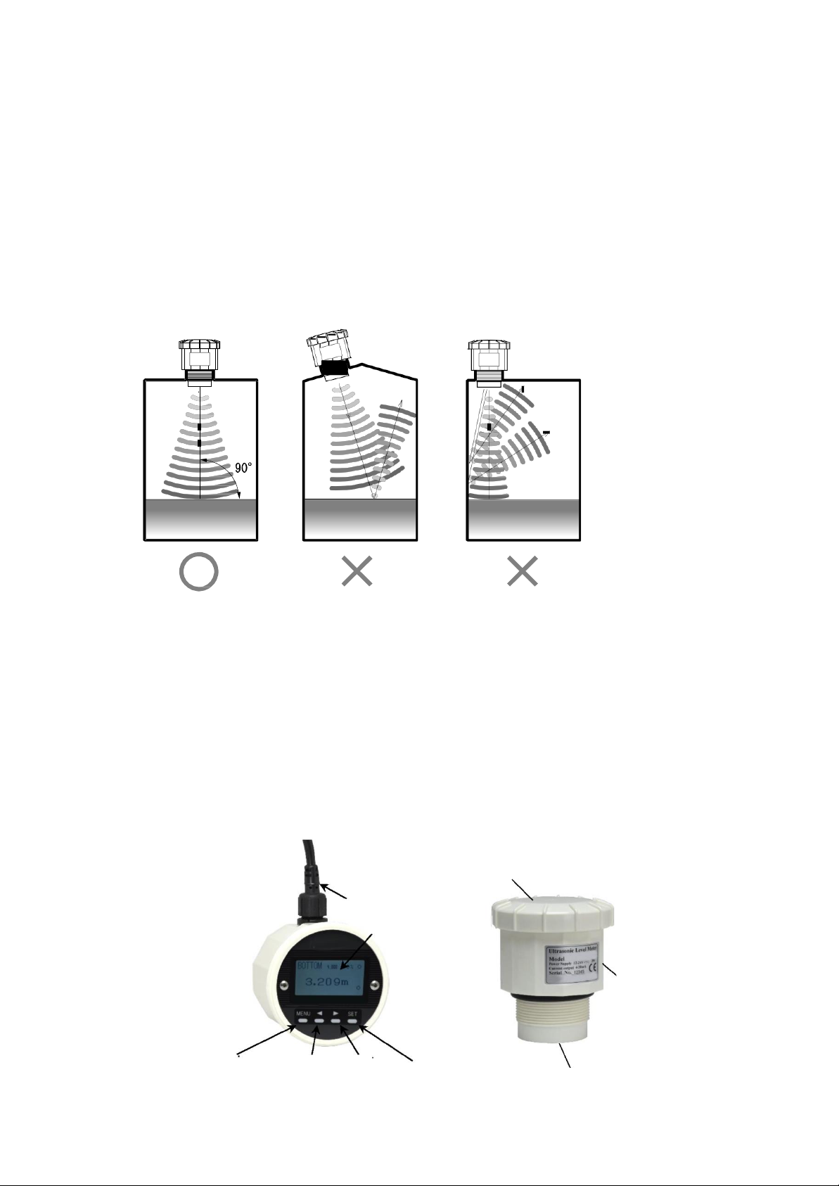
10.1 Installation precautions
➢EAX30000-B should be mounted 1/3 the diameter of the vessel from the vessel wall
➢Unit should never be closer than 300mm (12") to the liquid surface
➢Install EAX30000-B on the top of tank horizontally.
➢Screw in EAX30000-B into the resin flange with G2(2”PF) to the tank.
➢Do not use metal nut or flange to install EAX30000-B to the tank to avoid the
incorrect measurement. Use the resin nut or flange to install EAX30000-B to
the tank.
➢Install EAX30000-B so thatthe ultrasonic transmitting surfacebecomes parallel
to the liquid surface.
➢Do not install EAX30000-B close to the sidewall of tank to avoid the incorrect
➢measurement due to the undesired reflections from the sidewall.
➢Do not screw in EAX30000-B with too much force.
➢Avoid the direct sunlight to EAX30000-B.
➢Do not install the multiple ultrasonic sensors to the same tank. To avoid the
mutual interference of ultrasound.
10.2 Names of parts
Connector of
distribution cable
Lid
Main unit
Ultrasonic transmitting surface
MENU key
SET key
◄key
►key
LCD window

9
10.3 Settings according to the tank
1) Press MENU key to indicate MENU.
2) Change the indicated parameter by◄►keys and select the parameter by SET key.
Change the setting value by◄►keys.
Press SET key again to determine the setting value. Press MENUkey not to determine
the setting value.
3) B ZERO;
Distance from the ultrasonic transmitting surface to the tank bottom
B ZERO can be the distance from the ultrasonic transmitting surface to arbitrary 0% level.
4) SPAN;
Level from 0% to 100%
Set the level from 0% which is set at B ZERO to 100%.
5) SW H/L;
Level setting of alarm switch
Set the level of SW H/L ON/OFF.
Pay attention to the functions of SW H/L ON/OFF.
6) 4mA OFST;
Set the offset of 4mA output.

10
11. Parameter Functions
11.1 Operating Instructions
Basic key operation
Press MENU key to indicate MENU.
Change the indicated parameter by◄►keys and select the parameter by key. Change the
setting value by◄►keys.
Press SET key again to determine the setting value. Press SET key not to determine the
setting value.
Press MENU key again to escape from MENU.
Operating mode
There are 2 operating modes, Level meter mode and Weir flowmeter mode. Select the
operating mode at 20.FLOWmod in MENU.
Display mode
Select the display mode from the following 4 modes.
The selectable display modes depend on Level meter mode and Weir flowmeter mode.
<Level meter mode>
A ······TOP-based distance display
B ······BOTTOM-based level display
C······% display
D······Ultrasonic A mode display
<Weir flowmeter mode>
A ······Weir flowmeter display
B ······BOTTOM-based level display
C······% display
D······Ultrasonic A mode display
11
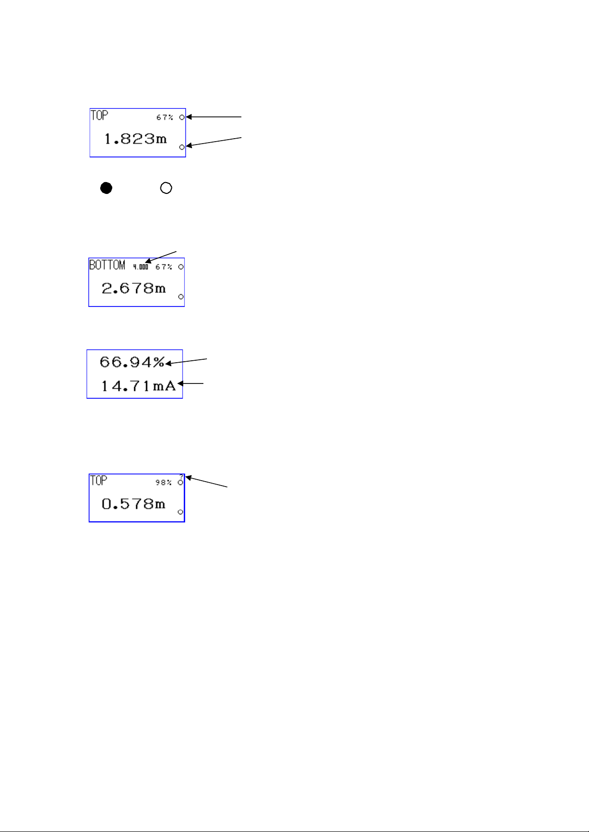
DISPMODE A - C <Level meter mode>
DISPMODE A (TOP-based distance display)
SW action indication;
ON: OFF:
DISPMODE B (BOTTOM-based level display)
DISPMODE C (% display)
Switch DISPMODE by◄►keys.
<Measurement error indication>
“?” is indicated at the upper right corner when the ultrasonic reflection echo cannot be
detected.
Rate of remaining amount in the tank
SPAN setting value
Output current value
“?” is indicated.
SW H action indication
SW L action indication

12
DISPMODE A - C <Weir flowmeter mode>
DISPMODE A (Weir flowmeter display)
tF: Total flow
iF: Instantaneous flow
DISPMODE B (BOTTOM-based level display)
DISPMODE C (% display)
Total flow
Instantaneous flow
Rate of instantaneous flow
SPAN setting value
Rate of instantaneous flow
Output current value

13
DISPMODE D (Ultrasonic A mode display)
Set the parameters related to the ultrasonic measurement based on the indicated waveform
of ultrasonic reflections.
Measured value and setting value are indicated at the bottom of display. Change the
indicated parameter by◄►keys and select the parameter by SET key.
(While selecting, underlined characters are indicated.)
Change the setting value by◄►keys after the parameter is selected and determine the
setting value by SET key.
●Indicated/Settingparameter
Indicated parameters:0>: Measured value s: Signallevel n: Noise level
<1> RANGE: Indicated range scale
Setting range: Min. 1m - Max. 10m (1m step)
<2> STC: Sensitivity Time Control
Sensitivity of close range is decreased to lower the undesired
reflections from the close range.
Setting range: 0 - 10 (Default: 0)
Larger value: Sensitivity of close range is lower.
<3> Att.c: Mask level for the entire area
Mask level gets lower according to the ultrasonic attenuation
based on the distance from the sensor.
Att.c=0dB Att.c=60dB
Threshold level line
Indicated/setting parameters of DISPMODE D

14
<4> maskP: Start position of rectangular mask
<5> maskW: Rectangular mask width
<6> maskLv: Rectangular mask level
Settings of rectangular mask to avoid the undesired reflectionsfrom
an obstacle within the measuring range.
Att.c=0dB Att.c=60dB
<7> Fmask: Reverb mask width
Reverb mask width should be wider to avoid incorrect measurement
when the oscillation reverb is too long.
[Caution] Distance within Reverb mask width cannot be measure at all.
<8> THRESH: Threshold level
Setting range: -4bB - -36dB (Default: -20dB)
Signalat the threshold level and lower is notbedetected. Threshold
level should be larger when 2 or 3 times that of actual distance is
detected caused by the multiple reflections.
<9> FREQ: Ultrasonic frequency
Setting range:
EAX30000-A :45 - 55kHz (1kHz step)
EAX30000-B 90 - 110kHz (1kHz step)
Set the value so that the signal level can be larger.
<10>NoiseSup: Noise suppression
Setting range: 0 - 3
Select the value so that the noise level can be smaller.
Fmask: 0.30m
Fmask: 0.45m
Fmask: 0.˙70m

15
11.2 Menu Setup
Press MENU key to indicate MENU.
Press MENU key again to escape from MENU.
After no key operation for 3 min., the display returns to the main display,
automatically.
DISPMODE: A - D
Select the appropriate one.
B ZERO: EAX30000-A: 0.5 - 10m
Set the distance from the ultrasonic transmitting surface to the tank bottom or the
channel floor.
SPAN: EAX30000-A: 0 - 10m
Set the measuring range from the tank bottom or Max. overflow level.
SPAN is the range of 4-20mA output.
[Caution] If “4mAOFST” is any other than 0, “4mAOFST” to “SPAN” is 4-
20mA output range.
RESPONSE: 1000m/min - 0.01m/min
Fast <-> Slow
Set the response speed to the measured distance change.
SW H ON/OFF:EAX30000-A: 0 –10m
Set the level from the tank bottom to turn ON/OFF the upper limit
SW.
SW L ON/OFF: EAX30000-A:0 –10m
Set the level from the tank bottom to turn ON/OFF the upper limit
SW.
[Caution] The function of SW ON/OFF depends on the setting value of SW H/L ON/OFF.
[Caution] In case SW H/L ON and OFF are switched frequently, the
difference between SW H/L ON and OFF should be larger to give hysteresis
characteristics.
4mA OFST: 0 –SPAN or lower
“4mAOFST=0” means that the tank bottom is the distance/level of
4mA output.
[Caution] If “4mAOFST” is any other than 0, “4mAOFST” to “SPAN” is 4-
20mA output range.
I4-20: Norm(Normal) or Reve(Reverse) Set the basis of 4-20mA output. Normal: 4mA =
0%, 20mA = 100% Reverse: 20mA = 0%, 4mA = 100%
*If any other than 0 is set to [4mA OFST], OFFSET works at 0% side.

16
BRIGHT: OFF <-> AUTO <-> ON
Set the back light function.
AUTO: ON for 10 min. after power power-on, OFF after 10 min. passes
1 hour: ON for 1 hour after any key operation, OFF after 1 hour passes
4-20SET: normal <-> i4mA - i20mA
Parameter for the connection test of 4-20mAoutput. normal: Current of
measured value is output.
i4mA: 4mA is output forcibly. I20mA: 20mAis output
forcibly.
normal <-> i4mA <-> i8mA <-> i12mA <-> i16mA <-> i20mA Once escape from
MENU, setting gets “normal”.
Dist Adj: -50 - +50mm
Set the value for the distance correction.
Err Cond: hold <-> i4fix <-> i20fix
Set the current output for the measurement error.
Hold: Current output of measured value before measurement error happens is output.
i4fix: 4mA is output when the measurement error happens. i20fix: 20mAis output
when the measurement error happens.

17
11.3 Weir flowmeter setting
FLOWmod: Selection of Weir flowmeter function
OFF: Level meter mode
Others: Weir flowmeter mode
Level meter mode: OFF
90 deg V-notch weir: 90ang
Arbitrary V-notch weir: AngleV
Contracted rectangular weir: Squar1
Suppressed rectangular weir: Squar2

18
Parshall flume flowmeter
<-> PF-1(1inches) <-> PF-2(2inches) <-> PF-3(3inches)
<-> PF-6(6inches) <-> PF-9(9inches) <-> PF-10(1feet)
<-> PF-15(1.5feet) <-> PF-20(2feet) <-> PF-30(3feet)
<-> PF-40(4feet) <-> PF-50(5feet) <-> PF-60(6feet)
<-> PF-70(7feet) <-> PF-80(8feet)
FBZERO: Distance from the ultrasonic transmitting surface to the channel floor
Setting range: 0.3 - 5m
FSPAN: Max. overflow level
Setting range: 0.05 - 3m
Max. measurable flow depends on FSPAN.
While FSPAN is set, Max. measurableflow is showed at the bottom
of display as “MaxFlow=XX.XXm3
B WIDTH: Channel width
Setting range: 0.4 - 32m
D SPAN: Height from the channel floor to the lower edge of weir
Setting range: 0.001 - 3.5m
sbWIDTH: Cutout width of contracted rectangular weir
Setting range: 0.15 - B WIDTH
V ANGLE: Arbitrary angle of V-notch (for AngleV) Setting
range: 45.0 - 100.0 deg
F CUT OF: Low cut OFF of flow
Setting range 0.0 - 10.0% of Max. measurable flow Flow at F CUT
OF or lower is recognized as no flow. Output current of flow at F
CUT OF or lower is 4mA.
While FSPAN is set, Max. measurableflow is showed at the bottom
of display as “MaxFlow=XX.XXm3
Parshall flume setting
FBZERO: Distance for Min. flow
FSPAN: Distance for Max. flow
Table of contents
Other FineTek Transmitter manuals


