Fiberplex TD-1581 User manual

USERMANUAL
FULLYCOMPATIBLEEIA‐530/6X4RS‐422SERIAL
INTERFACEwith1x2RS‐232
TD‐1580
/
TD‐1581

[Thispageintentionallyleftblank]

WarningforYourProtection
1.Readtheseinstructions.
2.Keeptheseinstructions.
3.Heedallwarnings.
4.Followallinstructions.
5.Donotusethisapparatusnearwater.
6.Cleanonlywithadrycloth.
7.Donotblockanyoftheventilationopenings.Installinaccordancewiththemanufacturer’sinstructions.
8.Donotinstallnearanyheatsourcessuchasradiators,heatregisters,stoves,orotherapparatus(includingamplifiers)thatproduceheat.
9.Donotdefeatthesafetypurposeofthepolarizedorgrounding‐typeplug.Apolarizedplughastwobladeswithonewiderthantheother.A
groundingtypeplughastwobladesandathirdgroundingprong.Thewidebladeorthethirdprongisprovidedforyoursafety.Iftheprovidedplug
doesnotfitintoyouroutlet,consultanelectricianforreplacementoftheobsoleteoutlet.
10.Protectthepowercordfrombeingwalkedonorpinched,particularlyatplugs,conveniencereceptacles,andthepointwheretheyexitfromthe
apparatus.
11.Onlyuseattachments/accessoriesspecifiedbythemanufacturer.
12.Useonlywiththecart,stand,tripod,bracket,ortablespecifiedbythemanufacturer,orsoldwiththeapparatus.Whenacartisused,use
cautionwhenmovingthecart/apparatuscombinationtoavoidinjuryfromtip‐over.
13.Unplugthisapparatusduringlightningstormsorwhenunusedforlongperiodsoftime.
14.Referallservicingtoqualifiedservicepersonnel.Servicingisrequiredwhentheapparatushasbeendamagedinanyway,suchaspower‐supply
cordorplugisdamaged,liquidhasbeenspilledorobjectshavefallenintotheapparatus,theapparatushasbeenexposedtorainormoisture,does
notoperatenormally,orhasbeendropped.
Theapparatusshallnotbeexposedtodrippingorsplashing.Noobjectsfilledwithliquids,suchasvases,shallbeplacedontheapparatus.
“WARNING:Toreducetheriskoffireorelectricshock,donotexposethisapparatustorainormoisture.”
GeneralInstallationInstructions
Pleaseconsiderthesegeneralinstructionsinadditiontoanyproduct‐specificinstructionsinthe“Installation”chapterofthismanual.
Unpacking
Checktheequipmentforanytransportdamage.Iftheunitismechanicallydamaged,ifliquidshavebeenspilledorifobjectshavefallenintothe
unit,itmustnotbeconnectedtotheACpoweroutlet,oritmustbeimmediatelydisconnectedbyunpluggingthepowercable.Repairmustonlybe
performedbytrainedpersonnelinaccordancewiththeapplicableregulations.
InstallationSite
Installtheunitinaplacewherethefollowingconditionsaremet:
Thetemperatureandtherelativehumidityoftheoperatingenvironmentmustbewithinthespecifiedlimitsduringoperationofthe
unit.Valuesspecifiedareapplicabletotheairinletsoftheunit.
Condensationmaynotbepresentduringoperation.Iftheunitisinstalledinalocationsubjecttolargevariationsofambient
temperature(e.g.inanOB‐van),appropriateprecautionsmustbetaken.
Unobstructedairflowisessentialforproperoperation.Ventilationopeningsoftheunitareafunctionalpartofthedesignandmust
notbeobstructedinanywayduringoperation(e.g.‐byobjectsplaceduponthem,placementoftheunitonasoftsurface,or
improperinstallationoftheunitwithinarackorpieceoffurniture).
Theunitmustnotbeundulyexposedtoexternalheatsources(directsunlight,spotlights).
AmbientTemperature
UnitsandsystemsbyFiberPlexaregenerallydesignedforanambienttemperaturerange(i.e.temperatureoftheincomingair)of+5...+40°C.
Whenrackmountingtheunits,thefollowingfactsmustbeconsidered:
Thepermissibleambienttemperaturerangeforoperationofthesemiconductorcomponentsis0°Cto+70°C(commercial
temperaturerangeforoperation).
Theairflowthroughtheinstallationmustallowexhaustairtoremaincoolerthan70°Catalltimes.
Averagetemperatureincreaseofthecoolingairshallbeabout20C°,allowingforanadditionalmaximum10C°increaseatthe
hottestcomponents.
Ifthecoolingfunctionoftheinstallationmustbemonitored(e.g.forfanfailureorilluminationwithspotlamps),theexhaustairtemperaturemust
bemeasureddirectlyabovethemodulesatseveralplaceswithintheenclosure.
GroundingandPowerSupply
Groundingofunitswithmainssupply(classIequipment)isperformedviatheprotectiveearth(PE)conductorintegratedinthree‐pinPhoenix™
connector.Unitswithbatteryoperation(<60V,classIIIequipment)mustbeearthedseparately.Groundingtheunitisoneofthemeasuresfor
protectionagainstelectricalshockhazard(dangerousbodycurrents).Hazardousvoltagemaynotonlybecausedbydefectivepowersupply
insulation,butmayalsobeintroducedbytheconnectedaudioorcontrolcables.
Thisequipmentmayrequiretheuseofadifferentlinecord,attachmentplug,orboth,dependingontheavailablepowersourceatinstallation.If
theattachmentplugneedstobechanged,referservicingtoqualifiedpersonnel.

Warranty,ServiceandTermsandConditionsofSale
ForinformationaboutWarrantyorServiceinformation,pleaseseeourpublished‘TermsandConditionsof
Sale’.Thisdocumentisavailableonfiberplex.comorcanbeobtainedbyrequestingitfrom
[email protected]orcalling301.604.0100.
Disposal
DisposalofPackingMaterials
Thepackingmaterialshavebeenselectedwithenvironmentalanddisposalissuesinmind.Allpackingmaterial
canberecycled.Recyclingpackingsavesrawmaterialsandreducesthevolumeofwaste.Ifyouneedto
disposeofthetransportpackingmaterials,recyclingisencouraged.
DisposalofUsedEquipment
Usedequipmentcontainsvaluablerawmaterialsaswellassubstancesthatmustbedisposedof
professionally.Pleasedisposeofusedequipmentviaanauthorizedspecialistdealerorviathepublicwaste
disposalsystem,ensuringanymaterialthatcanberecycledhasbeen.Pleasetakecarethatyourused
equipmentcannotbeabused.Afterhavingdisconnectedyourusedequipmentfromthemainssupply,make
surethatthemainsconnectorandthemainscablearemadeuseless.
Disclaimer
Theinformationinthisdocumenthasbeencarefullycheckedandisbelievedtobeaccurateatthetimeof
publication.However,noliabilityisassumedbyFiberPlexforinaccuracies,errors,oromissions,norforlossor
damageresultingeitherdirectlyorindirectlyfromuseoftheinformationcontainedherein.

Introduction
TheTD‐1580andTD‐1581pairtogethertoformapowerfulbalancedserialdatatransportsolution.TheDB‐25
connectorsarepinnedouttodirectlysupportanEIA‐530seriallink.Howeverduetothetransparencyand
flexibilityofthedesign,theTD‐1580/81canbeusedas6x4independent6MbpsRS‐422channelsand2x1
independent256KbpsRS‐232channels.
Thisincredibleversatilitycansolveamyriadofserialdatacommunicationsproblems.Youroncelimitedserial
linkscannotonlybeconsolidatedbutextendedtoover20Kmonasinglefiberpair.SCADA(supervisory
controlanddataacquisition),Telecommunications,FacilityAutomationandControl,evenDMXLighting
controlapplicationscanallbenefitfromtheTD‐1580/81.
Formoreadvancedsystems,a‘Regeneration’switchontheTD‐1581allowsuserstotogglebetween
synchronousapplicationsthatrequireSendTiming(ST)andasynchronousorsynchronousapplicationsthat
requireTerminalTiming(TT).
KeyFeatures
Compatiblewith:
oTIA/EIA‐530(RS‐530)
oMIL‐STD‐188‐114Abalancedtype1andtype2
oFEDSTD1030A
Canalternatelybeusedfor
6x4RS‐422and1x2RS‐232
EIA‐530andRS‐422channelssupportdataratesfromDCto6.144Mbps
Canbeusedforupto6universesofDMXlightingcontrol
Includespoweradapteraswellasa3‐positionPhoenix™
TheoryofOperation
ByusingatechnologyuniquetoFiberPlexproductscalled‘transparency’,weareabletousealltheclock,data
andcontrolchannelsofthestandardEIA‐530interfacecompletelyindependentlyofoneanother.This
providestheabilitytohave(4)bi‐directionalRS‐422serialwith(2)unidirectionalRS‐422and(1)bi‐directional
RS‐232with(1)uni‐directionalRS‐232,orevenindependentlyas(6)RS‐422inonedirectionand(4)inthe
other[6x4]and(2)RS‐232inonedirectionand(1)intheother[2x1].Thetablelaterinthemanualshowshow
thesechannelsarepinnedout.
DifferencesbetweenTD‐1580andTD‐1581
TheTD‐1580hasafemale(sockets)DB‐25connectorandmateswiththeDTE.
TheTD‐1581hasamale(pins)DB‐25connector,mateswiththeDCEandhasclockregenerationfunctions.
GettingStarted
InitialInspection
Immediatelyuponreceipt,inspecttheshippingcontainerfordamage.Thecontainershouldberetaineduntil
theshipmenthasbeencheckedforcompletenessandtheequipmenthasbeencheckedmechanicallyand
electrically.Iftheshipmentisincomplete,ifthereismechanicaldamage,oriftheunitfailstooperatenotify
FiberPlexandmaketheshippingmaterialsavailableforthecarrier'sinspection.
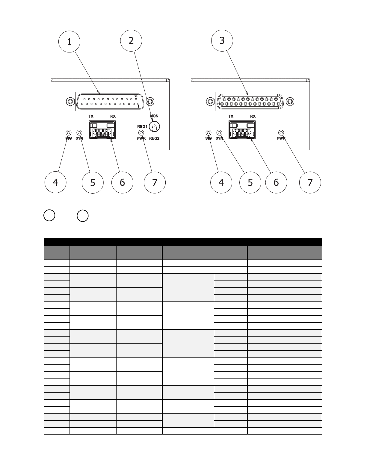
FrontIndicators/Connections
Figure1TD‐1581(left)andFOI‐1580(right)FrontFace
DCE&DTEConnectors–MaindataconnectionsviaD‐subminiature,25‐positionconnector.The
DCEisamale(pins)andtheDTEisafemale(sockets)connector.Jackscrewsareprovidedforsecurement.See
pinoutbelow.
PINOUTS
PinFOI‐4451(DCE)
Direction
FOI‐4541(DTE)
Direction
6x4SerialConfigurationEIA‐530Configuration
1 ChassisGroundChassisGround
7 SignalGroundSignalGround
2OutIn
Channel1RS‐422
TX+SendDataA(SD)
14TX‐ SendDataB(SD\)
3InOutRX+ReceiveDataA(RD)
16RX‐ ReceiveDataB(RD\)
4OutInChannel2RS‐422
TX+RequestToSendA(RTS)
19TX‐ RequestToSendB(RTS\)
5InOutRX+ClearToSendA(CTS)
13RX‐ ClearToSendB(CTS\)
20OutInChannel3RS‐422
TX+TerminalReadyA(TR)
23TX‐ TerminalReadyB(TR\)
6InOutRX+DataSetReadyA(DSR)
22RX‐ DataSetReadyB(DSR\)
24OutInChannel4RS‐422
TX+TerminalTimingA(TT)
11TX‐ TerminalTimingB(TT\)
8InOutRX+ReceiveTimingA(RT)
10RX‐ ReceiveTimingB(RT\)
15InOutChannel5RS‐422RX+SendTimingA(ST)
12RX‐ SendTimingB(ST\)
17InOutChannel6RS‐422RX+ReceiverReadyA(RR)
9RX‐ ReceiverReadyB(RR\)
18OutInChannel1RS‐232TXLocalLoopback(LL)
25InOutRXTestMode(TM)
21OutInChannel2RS‐232TXRemoteLoopback(RL)
13

RegenerationModeSwitch–TheREG1andREG2switchpositionisdeterminedbythedatarateofthe
RS‐422linkandthedistancebetweentheDCEandtheDTE.Insomecases,ifthetimingdelaysarejust
right,alinkwillfunctionin2switchpositions,NONandREG1,orNONandREG2.Itisalsopossibleforalinkto
operateinall3switchpositions;NON,REG1,andREG2.However,insynchronousapplicationswheretheDCE
providesSendTiming(ST),itwouldbemorebeneficialtouseeitherREG1orREG2ratherthanNONbecause
regenerationeliminatesthesamplingjitterfromtheTransmitData(TD)totheDCE.Seethetablebelow.
LabelPositionDescription
NONUp
TypicallysetforasynchronousorsynchronousapplicationsrequiringTerminalTiming(TT).
TransmitData(TD)andTerminalTiming(TT)fromtheDTEarebothpassedtransparentlytothe
DCEwiththeadditionofnormalpropagationdelayandsamplingjitter.
RegenerationModes
TypicallysetforsynchronousapplicationsrequiringSendTiming(ST).Thismaybeusedtocorrectfortimingdelaysover
longrunsofwiringbetweentheDCEandtheDTE.TerminalTimingfromtheDTEisignoredandwillnotbepassedtothe
DCE.Instead,SendTiming(ST)fromtheDCEisloopedbacktotheTerminalTiming(TT)outputontheTD‐1580.
REG1MiddleTransmitData(TD)fromtheDTEissampledinontherisingedgeofSendTiming(ST)fromthe
DCE.
REG2DownTransmitData(TD)fromtheDTEissampledinonthefallingedgeofSendTiming(ST)fromthe
DCE.
SIG(signal)& SYN(sync)–LEDsindicatingthestatusofsignalpresenceorabsence,andsync
characterdetection.Seethetablebelow.
LabelColorDescription
SIG
GreenOpticalsignalindetected.
OffNoopticalsignalinoropticalleveltoolow.Checkthattheoppositeunithaspowerandthat
thefiberopticcablesareproperlyconnected.TheTXopticfromoneendofthenetwork
connectstotheRXopticattheoppositeendasshownunder“TYPICALAPPLICATION”.
SYN
GreenUnitisinsync.
OffNosynccharactersdetected.Unitisunabletoframetothedatastream.
SFPPort–InstallanopticalSFPinthisslot.ThisslotconformstotheSFPMSApinouts(INF‐8074i,moreinformation
laterinthismanual).AnystandardMSAcomplaintopticalSFPcanbeusedinthisslotthatsupportsaminimumdata
rateof346Mbps.
Unitsorderedwiththe“‐L5B”and“‐L22”optioncomewithanappropriateSFPpre‐installed.The“‐C”optionhasanempty
SFPcagethatcanaccepteitherausersuppliedSFPoraQuadraxSFP‐SFPcable(orderedseparately)forconnectiontothe
FiberPlexWDM16orWDM8.
PWR–LEDindicatingpresenceofDCpowerintheunit.TheLEDcanbeinterpretedaccordingtothefollowingtable.
StatusIndicator
GreenPowersupplyinFOIunitisoperatingproperly.
OffNopowerfromthePSQpowersupplyoropenresettablefuseinsidetheFOIunit.CheckthatthePSQ
powersupplyisoperatingproperly.IfthePSQpowersupplyisgood,separatetheFOIunitfromthe
PSQpowersupplyfor30secondsandthenreattachsothatthefuseinsidetheFOIunithastimeto
reset.IfthePWRledisstilloffornotconstant,replacetheFOIunit.
2
45
6
7

RearIndicators/Connections
Figure2RearFace
CircularDCPowerConnection–DCpowerentryfortheunit.ThisisastandardDCconnectionforuse
withtheincludedDCwallpoweradapter.
PhoenixDCPowerConnection–Secondarypoweroption.Thisiswiredindirectparallelwiththe
Circularconnectorandhastheadditionofapositiveearthchassisgroundconnection.Thiscanbeused
topowertheunitonaclientsuppliedpowerbuss.
PowerRequirementsandMounting
TheTD‐1580andTD‐1581comewitha9VDCwalladapterforpoweringtheunits.Alternately,usersupplied7‐
28VDCpowercanbeusedbyutilizingthePhoenixpowerconnectorontherearofthemodule.
IMPORTANT:Formanyserialdataapplicationsitisnecessarytoprovideapositiveearthgroundreference
forproperserialoperation.EarthgroundcanonlybesuppliedusingthePhoenixconnector.DCpowercan
stillbeappliedwiththewalladapterinconjunctionwithjusttheearthgroundonthePhoenix.
SurfaceMounting
AllTDmoduleshavetwokeyholemountingholesonthe
bottomoftheunit.Includedwithyourpackagingisa1:1
scaletemplateforspacingscrewsforsurface
mounting.Simplytransfermarkstothesurfaceusing
thetemplateasaguideandsecurethesupplied
1/2”#2woodscrewsleavingabout1/16”
belowthehead.Now,simply
lowertheTDmoduleoverthe
screwheadsandslidetosecure.
8
9
#2 Wood Screw, 1/2" Long, #1 Phillips
Drive
Lower TD Unit Over Screw
Heads,
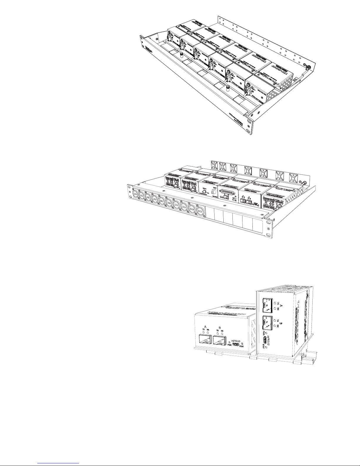
TDR‐01RearConnectRack
Complementingtheflexibilityofthe
FiberPlex‘TDSeries’offiberoptic
modules,theTDR‐01‐ACprovides
mounting,powerandcable
managementforupto6modulesina
compactandruggedaluminum1Urack.With
theTDmodulesrearfacing,connectionstotheTD
unitsaremadefromtherear,insideoftherack
enclosure.Theintegratedkey‐holemountingholesonthe
bottomtheTDunitslocksecurelyonmatingstudswhilearear
retentionbarholdsthemsecurelyinplace.A6positionwiring
harnessandincludedpoweradapterprovide,notjust9VDCpower,
butapositiveearthgroundtothemodulesvia3positionPhoenix™locking
powerconnectors.Managingallthatcablingandfibercansometimesbe
quiteachoresoanextendedcablingtraywithintegratedtiedownpointsareprovidedtohelpmakeyour
installationclean.
TDPFrontConnectRack
TheTDPprovidesfrontofrack
connection,mounting,power,
andcablemanagementforup
to6frontfacingTDmodulesin
acompactandruggedaluminum1U
rack.Eachofthe16channelsofthemodular
TDPfrontpanelcanaccommodateanyNeutrik™DSeries
connector,LCandSTbarrelconnectors,DB9connectors,etc.The
unusedpositionsaresimplyfittedwithablankpanel.Theintegratedkey‐hole
mountingholesonthebottomoftheTDunitslocksecurelyonmatingstudswhilearearretentionbarholds
themsecurelyinplace.A6positionpowerwiringharnessandincludedpoweradapterprovide,notjust9VDC
power,butapositiveearthgroundtothemodulesvia3positionPhoenix™lockingpowerconnectors.
Managingallthatcablingandfibercansometimesbequiteachore,theTDPallowsasimplesolutiontoput
maximumcapacityandflexibilityintoasingle1Uspace.
TD‐DINRDinRailMounting
TheFiberPlexTD‐DINRisaspecializedMountingBracket
intendedtomountasingleFiberPlexTD‐Seriesunitonto
DINrailconformingtostandardEN50022(tophat
sectionsonly).Either35x7.5mmor35x15mmsection
DINrailwillbecompatiblewiththisdevice.
Possiblemountingconfigurationsare:
Flatmounting,thelowerprofilebutwiderrailsignature
Or
Edgemounting,thehigherprofilebutnarrowerrailsignature

InsertingandRemovingSFPModules
IdentifytheLatchTypeoftheSFPModule
SFPModuleshavevariouslatchingmechanismstosecurethemintotheSFPCageofadevice.TheFiberPlex
WDMcansupportahostofmanufacturersandbrandsofSFPModulessotheusermayencounteranynumber
ofdifferentlatches.Someofthesearedescribedbelow.
BailClasp
ThebailclaspSFPmodulehasaclasp
thatyouusetoremoveorinstalltheSFP
module.
ActuatorButton
TheactuatorbuttonSFPmoduleincludesabuttonthatyou
pushinordertoremovetheSFPmodulefromaport.This
buttoncaneitherlift‘Up’orpress‘In’toreleasetheSFP
Moduledependingonthemanufacturer.
MylarTab
TheMylartabSFPmodulehasatabthat
youpulltoremovethemodulefroma
port.
SlideTab
TheslidetabSFPmodulehasatabunderneaththefrontofthe
SFPmodulethatyouusetodisengagethemodulefromaport.
HandlingWarnings
SFPModulesarestaticsensitive.Topreventdamagefromelectrostaticdischarge(ESD),itis
recommendedtoattachanESDpreventativewriststraptoyourwristandtoabaremetalsurfacewhen
youinstallorremoveanSFPModule.
DisconnectallopticalorcoppercablesfromSFPModulespriortoinstallingorremovingtheSFPModule.
Failuretodosocouldresultindamagetothecable,cableconnectorortheSFPModuleitself.Removing
andinsertinganSFPModulecanshortenitsusefullife,soyoushouldnotremoveandinsertSFPModules
anymoreoftenthanisabsolutelynecessary.
ProtectopticalSFPmodulesbyinsertingcleandustcoversintothemafterthecablesareremoved.Be
suretocleantheopticsurfacesofthefibercablesbeforeyouplugthembackintotheopticalportsof
anotherSFPmodule.AvoidgettingdustandothercontaminantsintotheopticalportsofyourSFP
modules,becausetheopticswillnotworkcorrectlywhenobstructedwithdust.

InsertingaModule
1) AttachanESD‐preventative
wristoranklestrap,followingits
instructionsforuse.
2) Disconnectandremoveall
interfacecablesfromSFP
Module.
3) IftheSFPModulehasaBail
Clasp,closetheBailClasp
beforeinsertingtheSFP
Module.
4) Withthegoldfingerconnectoronthebottomandthelabelonthetop,lineuptheSFPModule
withtheemptycageandslideitinmakingsurethatitiscompletelyinsertedandseatedinthe
cage.
RemovingaModule
1) AttachanESD‐preventative
wristoranklestrap,following
itsinstructionsforuse.
2) Disconnectandremoveallinterface
cablesfromSFPModule.
3) Releasethelatchingmechanism.
BailClasp–OpenthebailclaspontheSFP
Modulewithyourfingerinadownward
direction.
ActuatorButton–Gentlypressthe
actuatorup(orin)whilepullingthe
bodyoftheSFPModuletoreleasethe
SFPModulefromthecage.
MylarTab–Pullthetabgentlyina
straightoutwardmotionuntilit
disengagesfromtheport.Makesure
thetabisnottwistedwhenpullingasitmaybecomedisconnectedfromtheSFP
Module.
SlideTab‐Withyourthumb,pushtheslidetabonthe
bottomfrontoftheSFPmoduleinthedirectionofthe
equipmenttodisengagethemodulefromthelinecard
port.IfyoupullontheSFPmodulewithoutdisengaging
thetab,youcandamagetheSFPmodule.
4) GrasptheSFPModulebetweenyourthumbandindex
fingerandcarefullyremoveitfromtheport
5) PlacetheSFPModuleonanantistaticmat,or
immediatelyplaceitinastaticshieldingbagorcontainer
A
ctuator Button

OtherConsiderations
ApplicationFlexibility
TheunitssupporttailcircuitandnullmodemfunctionsforDCEtoDCEorDTEtoDTEcommunications.This
requirestwoofthesameTDunit.
Analternateinterface(V.35orRS‐232)maybeinstalledattheoppositeend,allowingtheusertocreatealink
betweentwoelectricallyincompatibleinterfaceswithoutrequiringaseparateinterfaceconverter.Formore
information,pleaseseethe“OpticalCompatibility”table.
SFPMSACompliance
TheSFPMultiSourceAgreement(MSA)isanagreementthatwasdraftedamongcompetingmanufacturersof
SFPopticalmodules.TheSFFCommitteewasformedtooverseethecreationandmaintenanceofthese
agreementsincludingtheSFPMSAdesignatedasINF‐8074i.Thisagreementdescribesamutuallyagreedupon
standardfortheformandfunctionofSFPmodules.However,notallSFPsproducedareMSAcompliant.The
MSAprovidesforatransceiver(TX/RX)pinout.OtherindustriessuchasbroadcasthadtheneedfordualTX
anddualRXSFPforuni‐directionalapplicationssuchasvideo.Naturally,anon‐MSAstandardwasintroduced
allocatingpinoutassignmentsfordualoutputanddualinputI/Oconfigurations.Inaddition,thesomeofthe
internalserialcommunicationpinswerereassigned.
TheTD‐1580/TD‐1581willonlyacceptMSAcompliantSFPmoduleswhichsupportthespecifieddatarate.
PinoutComparisonChart
PINTransceiver(MSA)Transceiver(Non‐MSA)DualTX(Non‐MSA)DualRX(Non‐MSA)
1VEEVEEVEEVEE
2TX_FAULT[VEE]VEENCRx2‐
3TX_DISNCNCRx2+
4MOD_DEF(2)‐SDAVEEVEEVEE
5MOD_DEF(1)‐SCLSCLSCLSCL
6MOD_DEF(0)–PRESENCE[VEE]SDASDASDA
7Rate[NC]VEEVEEVEE
8LOSRX1_LOSTx2+NC
9VEENCTx2‐ NC
10VEENCTx2_DISNC
11VEEVEEVEEVEE
12RD‐ Rx1‐ NCRx1‐
13RD+Rx1+NCRx1+
14VEEVEEVEEVEE
15VCCVCCVCCVCC
16VCCVCCVCCVCC
17VEEVEEVEEVEE
18TD+Tx1+Tx1+NC
19TD‐ Tx1‐ Tx1‐ NC
20VEETx1_DISTx1_DISNC
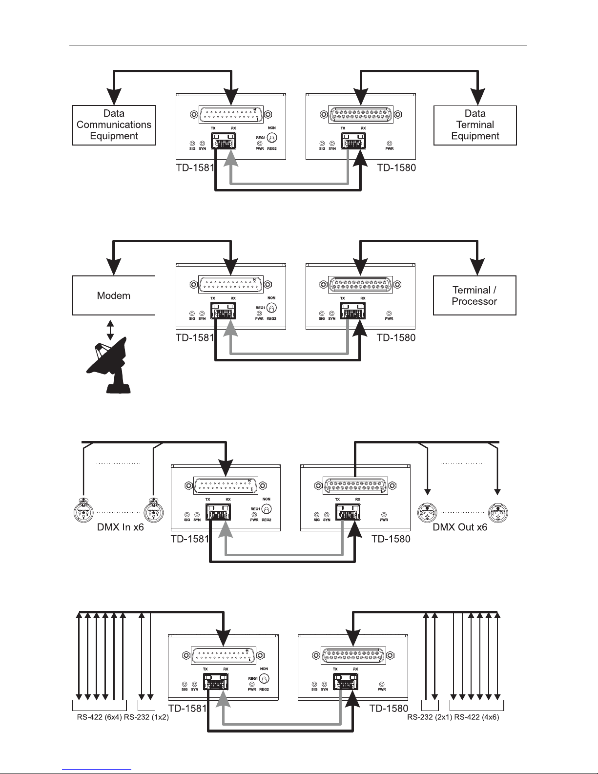
TypicalApplications
GenericFullProtocolEIA‐530/RS‐422Application
SATCOMRemoteDataLink
6ChannelDMXLighting
Multi‐ChannelDiscreteSerialData

Specifications
Dimensions

ELECTRICAL SPECIFICATIONS
MinTypMaxUnit
PowerRequirementVoltageRange7932V
SupplyCurrent‐625‐ mA
Balanced
DifferentialSignals
DataRateDC‐6.144Mbps
SamplingJitter0‐23%
InputLoad‐100‐ Ω
Common‐ModeInput
Voltage
‐ ‐ ±7V
Common‐ModeOutput
Voltage(100Ωload)
‐ 1.83V
Unbalanced
Single‐EndedSignals
DataRateDC‐120kbps
SamplingJitter0‐0.4%
InputLoad357kΩ
InputVoltageRange‐25‐ 25V
OutputVoltage(5kΩload)‐ ±5‐ V
EnvironmentalStorageTemperature‐40‐ 85°C
OperatingTemperature0‐50°C
InterfaceConnectorTD‐1581DB‐25Male
TD‐1580DB‐25Female
OPTICAL SPECIFICATIONS
ExternalSFPInterfaceMinTypMaxUnit
DataRate‐270‐Mbps
RecommendedJitter‐‐40Psec
OperatingVoltage‐3.3‐VDC
MaximumCurrent‐‐500mA
OpticalModulesSFPMSA(SFF‐8431,SFF‐8432,SFF‐8433)compliantslot,datarate266–1.25Gbps
PHYSICAL SPECIFICATIONS
CaseDimensionsLengthWidthHeightWeight
TD‐1580/TD‐15814.5in(114mm)2.75in(70mm)1.66in(42mm)0.4lb(0.2kg)

• 301.604.0100
UMT1580
150717
This manual suits for next models
3
Table of contents
Other Fiberplex Recording Equipment manuals


Popular Recording Equipment manuals by other brands


Lexicon
Lexicon OMEGA Desktop Recording Studio Bedienungsanleitung

AudioArts Engineering
AudioArts Engineering D-75 Technical manual

LST
LST FWI2-1 Specification sheet

thomann
thomann Tour Guide TG C18 user manual

ALLEN & HEATH
ALLEN & HEATH Xone VF-1 Service information

TS-market
TS-market EM CARD 16 Operation manual