FIBERROAD FR-5A3010P User manual
AI PoE Switch
This user manual describes installing and using the AI PoE Switch.
©2022 Fiberroad Technology Co., Ltd All right reserved Page 2 of 11
User Manual
Notes: 1. AI Extend: AI extend is a common PoE switch feature designed to extend PoE
distance up to 250m. The downside is that port speeds will be limited to only 10Mbps. This
limitation does not apply to the uplink ports. The AI Extend feature is suitable for situations
where your power source is too far away. There is, however, that bandwidth limitation to
be aware of.
2. AI VLAN: AI VLAN is essentially port isolation on each of the PoE ports. All PoE
ports are only able to communicate with the uplinks when this option is enabled. This can
be useful when the setup requires multiple clients to connect to a common network
resource but should not be able to connect to each other. Using this also improves network
security.
3. When AI QoS is enabled on the 8 port models, Port 1 - 4 will prioritise Video and
VoIP traffic flows over others. For example, an IP camera streaming in real-time takes
preference over a user transferring a backup file to a server.
4. AI PoE: The AI PoE feature allows the switch to check the ports for activity
periodically. If a port is not passing traffic for a certain amount of time, the switch will reset
the power on that specific port. The device on the other end will reboot with the idea that it
returns to a working state. This is a great feature to automate this process. It can save lots
of time on support and driving out to the site to troubleshoot or manually power cycle
equipment.
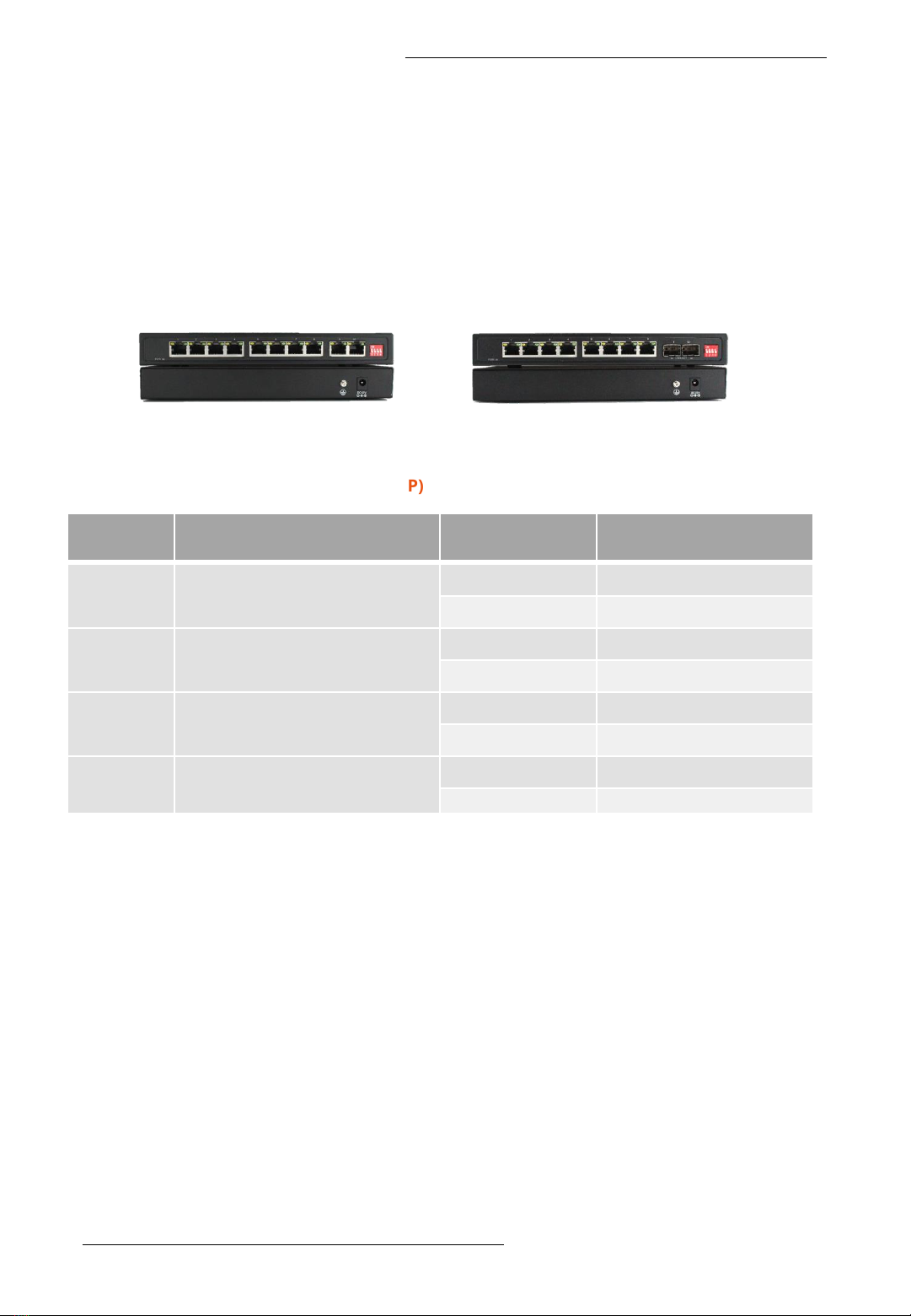
DIP
Switch Name Status Description
#1 AI Extend OFF Disable
ON Enable
#2 AI VLAN OFF Disable
ON Enable
#3 AI QoS OFF Disable
ON Enable
#4 AI PoE OFF Disable
ON Enable
❖DIP Switch (FR-5A3010P & FR-5A3208P)
Instruction
❖Optical Fiber Port
SFP Transceiver Module
You can select different SFP modules as required (Please refer to our SFP selection list for
the appropriate module). To insert/remove the SFP, the procedures are as follow:
1. On the side panel, insert the SFP module into the SFP port until it is securely locked.
2. Connect the optical fiber (1/2 core) to the LC connector(s) of the SFP.
3. To remove the SFP module, press down the lock of the LC connector of the optical fiber
to pull out the fiber cable.
4. Pull down the SFP lever and hold its position. Pull out the SFP module from the SFP port.
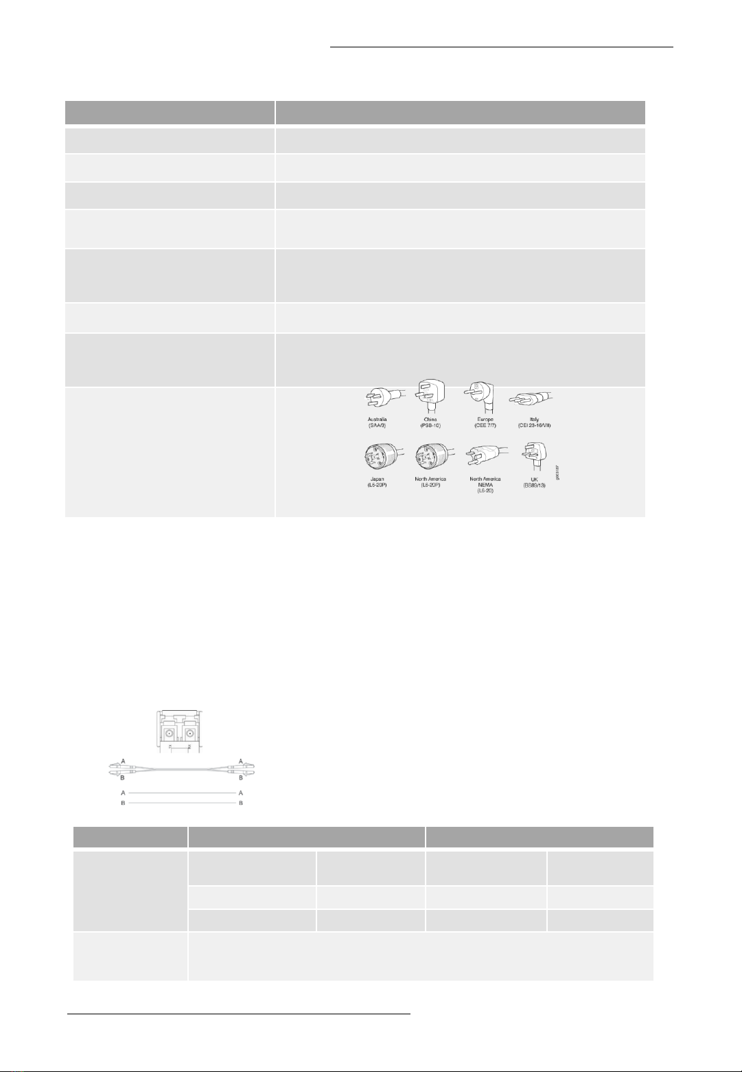
Notes: If you make your own cable, we suggest
labeling the two sides of the same line with the same
letter (A-to-A and B-to-B, shown as below, or A1-to-A2
and B1-to-B2).
❖PoE & Power Supply
User Manual
Item Specification
PoE Port Port 1 to 8 IEEE802.3af/at @PoE
Power Supply Pin Default: 1/2(+), 3/6(-),Optional:4/5, 7/8(-)
Max Power Per Port 30W; IEEE802.3af/at
Total PWR / Input Voltage 125W(DC52V) @ 15.4W
240W(DC52V) @ 30W
Power Consumption
Standby<4W
Full load<250W@30W
Power Inputs 1
Power Supply
External power adapter with AC100 –240V 50-60Hz input
52VDC 5A output@30W per port
52VDC 2A output@15.4W per port
AC Plug Types
©2022 Fiberroad Technology Co., Ltd All right reserved Page 3 of 11
Connector Multimode Fiber Sigle-mode Fiber
1000Base-
SX(850nm)
Bandwidth MHZ-KM Distance Bandwidth MHZ-
KM Distance
260 220m 400 500m
200 275m 500 550m
1000Base-LX
(1310nm/1550nm)
Single-mode Fiber 9/125um:2km
Single-mode Transceiver 1310nm: 10/20km
Single-mode Transceiver 1550nm: 40-120km
User Manual
©2022 Fiberroad Technology Co., Ltd All right reserved Page 4 of 11
LED State Indication
PWR On Power On
Off Power Off
LINK/ACT
On Valid Ethernet Link
Blink Data Transmission
Off No Ethernet Link
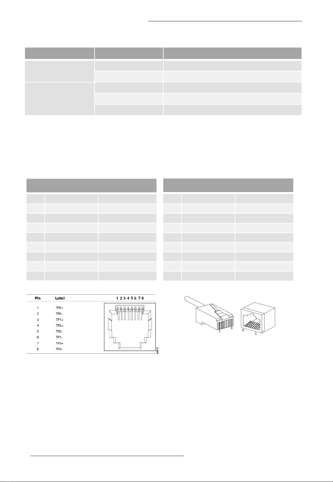
❖RJ45 Ethernet Port
Figure 1 10/100/1000M Lan Port Pinouts
10/100Mbps 10/100Base-T, RJ45 Connector Pin
Assignment
Pin MDI Signal Definition MDIX Signal Definition
1 TD+ RD+
2TD-RD-
3 RD+ TD+
4NC NC
5NC NC
6RD-TD-
7NC NC
8NC NC
RJ 45 port support automatic MDI/MDI-X operation. Can connect the PC, Server,
Converter and HUB .Pin 1,2,3,6 Corresponding connections in MDI. 1→3, 2→6, 3→1,
6→2 are used as cross wiring in the MDI-X port of Converter and HUB.
10/100/1000Base-TX are used in MDI/MDI-X, the define of Pin in the table as below.
1000Mbps 1000Base-T, RJ45 Connector Pin Assignment
Pin MDI Signal Definition MDIX Signal Definition
1 BI_DA+ BI_DB+
+ BI_DA- BI_DB-
3 BI_DB+ BI_DA+
4 BI_DC+ BI_DD+
5 BI_DC- BI_DD-
6 BI_DB- BI_DA-
7 BI_DD+ BI_DC+
8 BI_DD- BI_DC-
As aforementioned, an Ethernet crossover cable is adopted to connect two ports of the same
configuration (i.e. MDI-to-MDI or MDIX-to-MDIX). However, it may generate some confusion and
inconveniences when deploying two different kinds of Ethernet cables. The auto-MDI/MDIX
technology is developed to fix this problem: It automatically switches between MDI and MDIX as
required. Auto MDI/MDIX ports on newer device interfaces detect if the connection requires a
crossover, then automatically choose the MDI or MDIX configuration to properly match the other
end of the link. In this case, it doesn’t matter if you using straight through or crossover cables. The
chart below shows cable types for MDI/MDIX and auto-MDIX.
❖The Port Status LEDs (FR-POE233)

User Manual
©2022 Fiberroad Technology Co., Ltd All right reserved Page 5 of 11
Setting
MDI/MDIX Device Type
PC or other MDI Device Switch, hub or other MDIX Device
MDI Crossover cable Straight-through cable
MDIX Straight-through cable Crossover cable
Auto-
MDI/MDIX Either crossover or straight-through cable
❖Power over Ethernet(PoE) Pinout Diagram
Power over Ethernet or PoE is a standard system that transmits or delivers electrical
power along with data through the same cable. We know that there are different types of
network cables are available such as cat6, cat7, cat5, etc, and different types of ports also
available such as RJ45. RJ45 has a total of eight pins and it connects with an ethernet cable
that consists of eight separate wires. All these eight wires are not used for the data
transmission, so some of them can be used for electrical power transmission. As per the
standard, the electrical current should interface with the data transmission and the cable
should be safe.
The Power over Ethernet system works under the standardization of the (Institute of
Electrical and Electronics Engineers)IEEE 802.3 committee. Generally, PoE delivers 47-57V
DC power. This PoE system is used for both data and power transmission purposes in
Internet Protocol(IP) cameras, Wireless Access points(WAPs), Voice over Internet
Protocol(VoIP), etc.
According to the IEEE standard cat5 or better cable is required for the transmission of
high power levels. But cat3 cable also can be used if less power transmission is required.
The PoE system was physically implemented under the specification of IEEE 802.3af-2003.
Also, we know that there are two categories for the RJ45 colour code - T568A and T568B.
❖IEEE 802.3af -2003 Standard PoE Pinout Diagram for T568A
No. Description
1 White Green(TX+)
2 Green(TX-)
3 White Orange(RX+)
4 Blue(DC+) - PoE
5 White Blue(DC+) - PoE
6 Orange(RX-)
7 White Brown(DC-) - PoE
8 Brown(DC-) - PoE
*Hold the copper strips toward your face
No. Description
1 White Orange(TX+)
2 Orange(TX-)
3 White Green(RX+)
4 Blue(DC+) - PoE
5 White Blue(DC+) - PoE
6 Green(RX-)
7 White Brown(DC-) - PoE
8 Brown(DC-) - PoE

User Manual
©2022 Fiberroad Technology Co., Ltd All right reserved Page 6 of 11
❖Installation Preparation
Before installation, confirm that the work environment meets the installation
requirements, including the power needs and abundant space. Whether it is close to
the connection equipment and other equipment are prepared or not.
1. Avoid in the sunshine, keep away from the heat fountainhead or the area wherein
intense EMI.
2. Examine the cables and plugs that installation requirement.
3. Examine whether the cables be seemly or not (less than 100m) according to a
reasonable scheme.
4. Power: DC52V power input
5. Environment:
working temperature: 0~50℃(32 to 122℉)
Storage Temperature: -20~70℃ (-4 to +158℉)
Relative humidity 5%~95% (noncondensing)
Desktop Installation
To Install a PoE Switch on a desktop or shelf, simply complete the following steps:
Step 1:Attach the rubber feet to the recessed areas on the bottom of the PoE Switch.
Step 2: Place the PoE Switch on the desktop or shelf near an AC power source.
Step 3: Keep enough ventilation space between the PoE Switch and the surrounding
objects.
Step 4: Connect the PoE Switch to network 802.3at/802.3af powered device(PD) and
switch
Step 5: Supply Power to the PoE Switch
❖Wiring Requirements
Cable laying need to meet the following requirements,
1. It is needed to check whether the type, quantity and specification of cable match
the requirement before cable laying;
2. It is needed to check the cable is damaged or not, factory records and quality
assurance booklet before cable laying;
3. The required cable specification, quantity, direction and laying position need to
match construction requirements, and cable length depends on actual position;
4. All the cable cannot have break-down and terminal in the middle;
5. Cables should be straight in the hallways and turning;
6. Cable should be straight in the groove, and cannot beyond the groove in case of
holding back the inlet and outlet holes. Cables should be banded and fixed when
they are out of the groove;
7. User cable should be separated from the power lines. Cables, power lines and
grounding lines cannot be overlapped and mixed when they are in the same
groove road. When cable is too long, it cannot hold down other cable, but structure
in the middle of alignment rack;
8. Pigtail cannot be tied and swerved as less as possible. Swerving radius cannot be
too small (small swerving causes terrible loss of link). Its banding should be
moderate, not too tight, and should be separated from other cables;
9. It should have corresponding simple signal at both sides of the cable for
maintaining.
User Manual
©2022 Fiberroad Technology Co., Ltd All right reserved Page 7 of 11
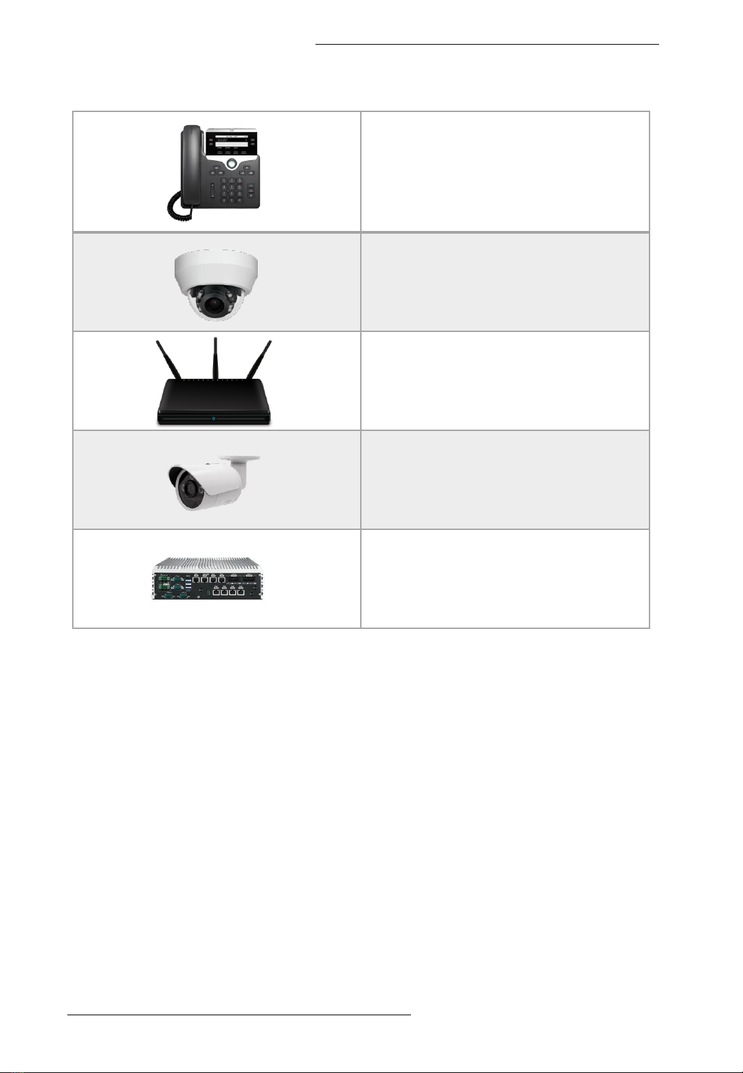
❖Power over Ethernet Powered Device
Voice over IP Phones
(3-5 Watts)
IP Camera
(10-12 Watts)
Wireless LAN Access Points
(6-12 Watts)
PAN/Tilt/Zoom Cameras
(30 Watts)
Remote Computer
(30 Watts)
❖PoE Power Supply Budget Calculation
Step1: Add Up The Demand For PoE In Watts
Add up the expected demand for power for each Powered Device (PD) in
watts. Allow for the maximum power and upper end of PD classification. Any
unspecified devices should be assumed Class 0.
For example, an IEEE802.3af, Class 0 device may consume 9 watts; however, as it’s
Class 0, assume 15.4 watts.
Round the numbers up, occasionally, to account for the additional consumption of
the UTP (unshielded twisted-pair) ethernet cable that runs between the PD and PoE
switch.
For example, if an IEEE802.3at Class 4 IP camera consumes 25.5 watts, round to 30
watts, which adds a buffer to balance out the loss between the PoE switch and the
device.

User Manual
©2022 Fiberroad Technology Co., Ltd All right reserved Page 8 of 11
Include room for future capacity. It’s convenient to have at least one spare port for
diagnostics, troubleshooting, or monitoring. And many clients want extra ports for the
option to add more PD devices in the future. However, as long as devices are
appropriately selected and integrated, accounting for spare ports isn’t required for a
PoE power budget calculation.
Step 2: Scale For The Operating Environment
When performing a PoE power budget calculation, it’s essential to account for
environmental conditions.
Accommodate for the conditions. Expect the long-term performance of a power
supply to be 70%of its rating in a benign/conditioned environment (somewhere with
steady temperatures between 32°F/0°C and 120°F/50°C).In a benign environment,
divide the total wattage from step one by 0.7.
If the power supply is subject to a harsh environment (cold temperatures less than
32°F/0°C or heat above 120°F/50°C), plan for diminished performance. Divide the total
wattage from step one by 0.6 for this type of setting.
In extreme conditions, industrial-grade modes, such as Fiberroad Industrial PoE Series,
DIN rail mountable, and DC 48V power supplies.
Take this harsh scenario, for instance:
A switch and its power supply will be stored in a metal enclosure, exposed to direct sun,
at a site in the northeastern United States. In winter, the temperature inside the
enclosure could be as low as –10°F/–24°C. And in summer, it could be as high as
140°F/60°C. Accounting for the temperature inflexions, expect the power supply to
operate at 60%of its power rating.
It’s always safe to assume a conservative long-term performance drop of 50%, no
matter the conditions. That means totalling the anticipated power demand (step 1) and
dividing by 0.5 (step 2) to get a power budget in watts.
Step 3: Select The Power Source
After determining the demand for PoE power and accounting for the surroundings, it’s
time to select an appropriate supply. Fiberroad has DC 48-56V supplies with ratings
from 30 watts to 480 watts.
❖Troubleshoot
⚫Please follow this step if the equipment have trouble.
⚫Make sure the equipment is installed according to the manufactures installation guide.
⚫Confirm RJ45 cable order meets EIA/TIA568A or 568B standard.
⚫Every PoE port can provide PoE equipment with a maximum power of less than 30W;
please do not connect the PoE equipment with control over 30W.
⚫Replace the equipment that can not work with a proper functioning 8port PoE Ethernet
switch to check if the equipment is damaged.
⚫Please get in touch with your vendor if trouble still exists.

User Manual
©2022 Fiberroad Technology Co., Ltd All right reserved Page 9 of 11
❖Specifications
Ethernet Interface
Model FR-5A3010P FR-5A3208P
RJ45 Port 8x10/100/1000Base-TX +
2x10/100/1000Base-Tx 8x10/100/1000Base-TX
Optical Fiber Port 2x1000Base-X(SFP)
SFP Slot Port
Gigabit SFP optical fiber interface, default
matching optical modules (optional order
single-mode / multi-mode, single fiber / dual
fiber optical module. LC)
Twisted Pair
Transmission
10BASE-T: Cat3,4,5 UTP(≤100 meter)
100BASE-TX: Cat5 or later UTP(≤100 meter)
1000BASE-T: Cat5e or later UTP(≤100 meter)
Port Mode(Tx)
Auto-Negotiation
Full/Half Duplex Mode
Auto MDI/MDI-X Connection
Standards
IEEE 802.3 for 10BaseT
IEEE 802.3u for 100BaseT(X) and 100BaseFX
IEEE 802.3ab for 1000BaseT(X)
IEEE 802.3z for 1000BaseSX/LX/LHX/ZX
IEEE 802.3x for flow control
IEEE 802.1p for Class of Service
IEEE802.3az Energy Efficient Ethernet
Packet Buffer Size 2Mbits
Maximum Packet
Length Up to 9K
MAC Address Table 4K
Transmission Mode Store and Forward (Full Wire Speed)
Exchange Property Delay time: < 7μs
Backplane bandwidth: 20Gbps
LED Indicator
Power Connect-always
RJ45 LINK/ACT: Connect-always; Data exchange-twinkle
Optical Fiber LINK/ACT: Connect-always; Data exchange-twinkle
Physical Characteristics
Housing Metal
IP Rating IP30
Dimensions 220*108*28 mm (L*W*H)
8.7*4.25*1.10 in (L*W*H)
Installation Mode Desktop
Weight 500g(1.10lb)

User Manual
©2022 Fiberroad Technology Co., Ltd All right reserved Page 10 of 11
Working Environment
Operating Temperature 0℃~50℃(32to 122 ℉)
Operating Humidity 5%~90% (non-condensing)
Storage Temperature -20℃~70℃(-4 to 158 ℉)
MTBF 100,819 Hours
MTBF Standard Telcordia SR-332 GB 25℃
Cooling Fanless, Passive Cooling
Noise Level 0 dBA
Certification & Warranty
Lightning Protection Surge Protection: 4kV 8/20us
Certification CE mark, commercial;CE/LVD EN60950; FCC Part 15 Class B;
RoHS
Warranty 3 years, lifetime technical support

User Manual
©2022 Fiberroad Technology Co., Ltd All right reserved Page 11 of 11
❖Regulatory Information
1.1 Electronic Emission Notices
This equipment has been tested and found to comply with the FCC Part 15, Subpart B, Class A
and protection requirements of European Emission Standard as follows: EMI Comply with FCC
Part 15 Class A & CE Mark Approval LVD EN 62368-1 Safety UL and others by request
1.2 FCC Class a statement
This equipment generates, uses, and can radiate radio-frequency energy, and if not installed
and used properly, that is, in strict accordance with the manufacturer’s instructions, may cause
interference to radio communication. It has been tested and found to comply with the limits
for a Class A computing device in accordance with the specifications in Subpart B of Part 15 of
FCC rules, which are designed to provide reasonable protection against such interference
when the equipment is operated in a commercial environment. Operation of this equipment in
a residential area is likely to cause interference, in which case the user at his own expense will
be required to take whatever measures may be necessary to correct the interference.
Changes or modifications not expressly approved by the party responsible for compliance
could void the user’s authority to operate the equipment.
This digital apparatus does not exceed the Class A limits for radio noise emission from digital
apparatus set out in the Radio Interference Regulation of Industry Canada.
1.3 Disclaimer
Fiberroad Technology Co., Ltd shall not be liable for damages of any kind, including, but not limited to,
punitive, consequential or cost of cover damages, resulting from any errors in the product information or
specifications set forth in this document and Fiberroad Technology Co., Ltd may revise this document at any
time without notice.
1.4 Trademarks used in this manual
Fiberroad Technology and the Fiberroad logo type and mark are registered trademarks of Fiberroad
Technology Co., Ltd . Any other trademarks mentioned in this manual are acknowledged to be the property
of the trademark owners.
This manual suits for next models
1
Table of contents
Other FIBERROAD Switch manuals


Popular Switch manuals by other brands


Comtrend Corporation
Comtrend Corporation GS-7620 Quick installation guide

Johnson Pump
Johnson Pump SPX AS888 instruction manual

3Com
3Com Baseline 2824 user guide

Intermatic
Intermatic T7401BC supplementary guide

Cross Technologies
Cross Technologies 1582-225L2 instruction manual

Konig
Konig CMP-EHUB41 manual