FIBERROAD 7 Series User manual


-
2
-
Overview
Thanks for your purchasing. Please read the Quick Installation Guide for better user
experience. Fiberroad 7 Series Industrial Ethernet Switch is environmentally hardened
at standard operating temperature range -40 to 75°C for stable operation in harsh
Industrial environment. The Industrial Switch is mini size, no fan, low power
consumption, high reliability and stability, and easy to maintain. Housed in rugged DIN
rail or wall mountable IP40 aluminum enclosures, these switches are perfect choices
for harsh environments, such as industrial networking, intelligent transportation
systems (ITS) and are also suitable for many military and utility market applications
where environmental conditions exceed commercial product specifications.
The Industrial PoE Switch can provide up to 30 watts of power per PoE+ port in
Ethernet 802.3at mode for industrial heavy-duty PoE devices, such as IP
surveillance cameras, IP phones and wireless access points. It is designed especially
for outdoor applications with 4KV~8KV surge resistance to keep continuous reliability
of the PoE systems.
The Industrial Managed Fiber Switch is high-performance layer 2 switch, with SFP
fiber ports transmitting data up to 120km from the device to control center with
effective immunity to EMI. The management function, includes STP/RSTP, MSTP,
ERPS, PoE power scheduling, PoE power management, PoE device auto-checking,
VLAN, IGMP, QoS, RMON, port mirroring, and bandwidth management etc.
Package List
The Industrial Switches is shipped with the following items. If any of these items are
missing or damaged, please contact your customer service representative for
assistance.
•
Industrial Fiber Ethernet Switch
•
Protective caps for unused SFP ports
•
DIN-Rail mounting kit
(attached to Industrial Switch’s rear panel by default)
•
Quick Installation Guide & User Manual (attached in CD)
•
Warranty card (Printed)

-
3
-
Panel Views of Industrial Switch
Front Panel View
1 2 1 3 3
5
1. PWR: Power on LED
2. Fiber: Fiber LED
3. LK/ACT: Fiber link active
4. SYS: Switch working
5. Green LED: Gigabit port speed LED
6. Yellow LED: Current port link up
7. LINK: Fiber link active
1 4
1 5
6
7

-
4
-
Top Panel View
99 10
8
8
11 10
11
12
8. PWR1: Terminal block power input 1
9. PWR2: Terminal block power input 2
10. Grounding M3 screw
11. 5V DC: Input voltage DC5V
12. RS-232 serial console port
13. Reset
910
8
13
11
12 13

-
5
-
Rear Panel View
15 17 19
15
16
18
15. Wall mounting plate
16. DIN-Rail mounting kit
17. Wall mounting hole M3 screw
18. Metal spring
19. Aluminum case for heat dissipation

-
6
-
Mounting Dimensions (unit = mm)
Small-size Industrial Switch - Unmanaged 2~5Ports
Medium-size Industrial Switch - Managed 5~10Ports
Big-size Industrial Switch - Managed 16~24Ports

-
7
-
LED Indicators
The front panel of the Industrial Switch contains several LED indicators.
The function of each LED is described in the following table:
DIN-Rail Mounting
When you take the Industrial Ethernet Switchout of the package., the aluminum DIN-Rail
attachment plate should be fixed to the back panel already. If you need to re-attach
the DIN-Rail attachment plate to the industrial switch, please make sure the stiff
metal spring is situated towards the top, as shown by the following pictures.
STEP 1 ☞
Insert the top of the DIN-Rail into the
slot just below the stiff metal spring.
STEP 2 ☞
The DIN-Rail unit will snap into place as
shown in the following illustration.
* To remove the Industrial Ethernet Switch from the DIN-Rail, simply reverse STEP 1
and STEP2 above.
LED
Color
State
Description
PWR
Green
On
Power is being supplied to power input.
Off
Power is not being supplied to power input
Fiber
LK/ACT
LINK
Yellow
On
Fiber link active
Off
Fiber link not working
SYS
Green
On
Switch working
Off
Switch non-working
-
8
-
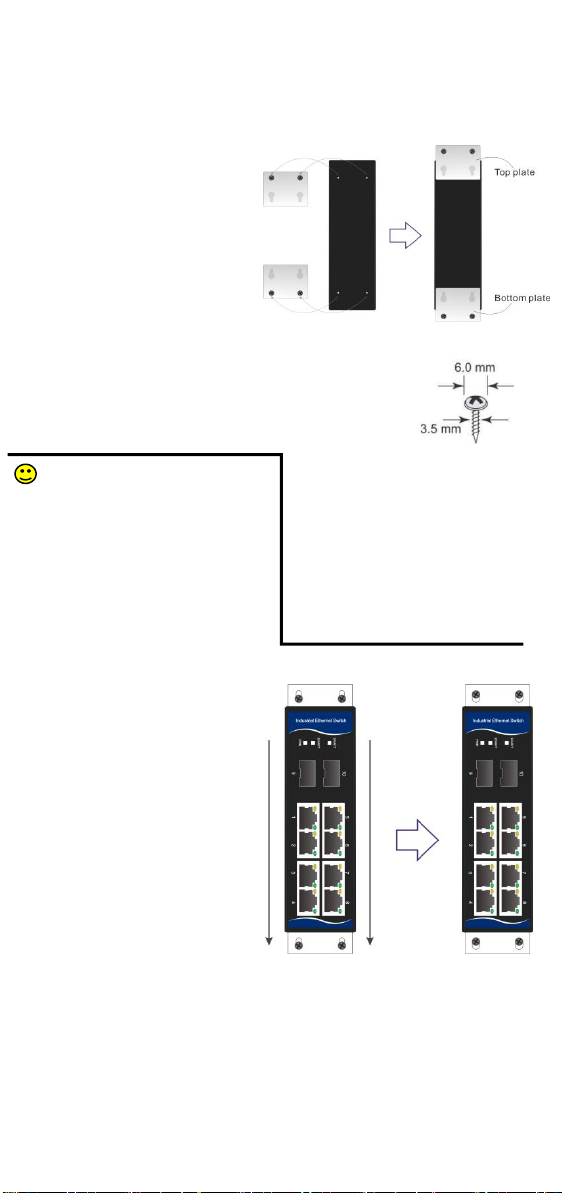
Wall Mounting
You will find it convenient to mount Fiberroad Industrial Switch on the wall for some
applications, as shown in the following figure:
STEP 1 ☞
Remove the aluminum DIN-Rail plate
from the rear panel of Industrial Switch,
and then attach the wall mount plates
with M3 screws as shown in the figure.
STEP 2 ☞
Mounting the Industrial Switch on the
wall requires 4 screws. Use the Industrial Switch, with
wall mount plates attached, as a guide to mark the correct
locations of the 4 screws. The heads of the screws should be less
than 6.0 mm in diameter, and the shafts should be less than
3.5mm in diameter as shown in the figure.
Before tightening the screws into the
wall, make sure the screw head and shank
size are suitable by inserting the screw
through one of the keyhole-shaped
apertures of the Wall Mounting Plates.
Do not screw the screws in all the way,
leave 2mm+/- to allow room for sliding
the wall mount panel between the wall
and the screws.
STEP 3 ☞
Once the screws are fixed to the wall,
insert the four screw heads through the
wide parts of the keyhole-shaped
apertures, and then slide the Industrial
Switch downwards, as indicated in the
figure. Tighten the four screws for more
stability.

-
9
-
Wiring Requirements
WARNING
Do not disconnect modules or wires unless power has been switched off or the area
is known to be non-hazardous. The devices may only be connected to the supply
voltage shown on the type plate. The devices are designed for operation with a
Safety Extra-Low Voltage. Thus, they may only be connected to the supply voltage
connections and to the signal contact with the Safety Extra-Low Voltages (SELV) in
compliance with IEC60950-1/EN60950-1.
ATTENTION
This unit is a built-in type. When the unit is installed in another piece of equipment,
the equipment enclosing the unit must comply with fire enclosure regulation
IEC60950-1/EN60950-1 (or similar regulation).
Safety First
Be sure to disconnect the power cord before installing and/or wiring your the
Industrial Switch.
Calculate the maximum possible current in each power wire and common wire.
Observe all electrical codes dictating the maximum current allowable for each wire
size. If the current goes above the maximum ratings, the wiring could overheat,
causing serious damage to your equipment.
Please read and follow these guidelines:
▶Use separate paths to route wiring for power and devices. If power wiring and
device wiring paths must cross, make sure the wires are perpendicular at the
intersection point.
NOTE: Do not run signal or communications wiring and power wiring through the same
wire conduit. To avoid interference, wires with different signal characteristics should be
routed separately.
▶You can use the type of signal transmitted through a wire to determine which wires
should be kept separate. The rule of thumb is that wiring that shares similar electrical
characteristics can be bundled together.
▶Please separate input wiring from output wiring.
▶Please label the wiring to all devices in the system.
-
10
-
Grounding the Industrial Switch
Grounding and wire routing help limit the effects of noise due to electromagnetic
interference. Run the ground connection from the ground screw to the grounding
surface prior to connecting devices.
ATTENTION
This product is intended to be mounted to a well-grounded mounting surface such as
a metal panel.
Wiring the Relay Contact (Optional)
The Industrial Switch has one relay output. The relay contact uses two contacts of the
terminal block on the Industrial Switch’s top panel. Refer to the next section for detailed
instructions on how to connect the wires to the terminal block connector, and how to
attach the terminal block connector to the terminal block receptor.
In this section, we illustrate the meaning of the two contacts used to connect the relay
contact.
FAULT✘
The relay contacts of the 2-pin terminal block connector are
used to detect user-configured events. The two wires
attached to the fault contacts form an open circuit when a
user-configured event is triggered. If a user-configured event
does not occur, the fault circuit remains closed.
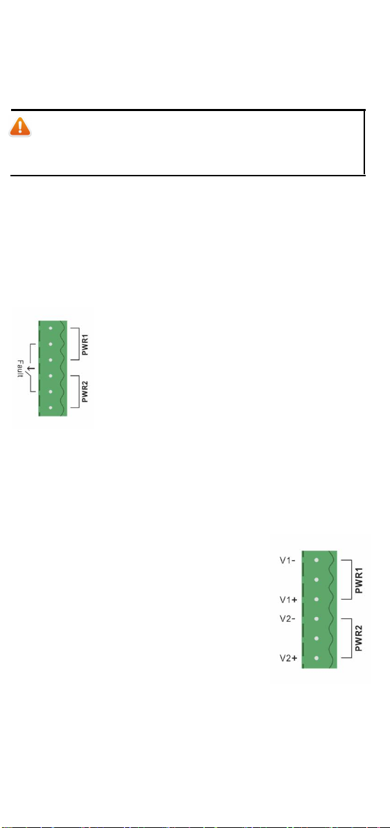
Wiring the Redundant Power Inputs
The Industrial Switch has two sets of power inputs—power input 1 and power input 2.
The two terminal block connectors on the top-left of the Industrial Switch's top panel are
used for the two power inputs. The top and front views of one of the terminal block
connectors are shown here.
STEP 1 ☞Insert the negative/positive DC
wires into the V-/V+ terminals, respectively.
STEP 2 ☞To keep DC wires from pulling loose, use
a small flat-blade screwdriver to tighten the wire-clamp
screws on the front of the terminal block connector.
STEP 3 ☞Insert the plastic terminal block connector
prongs into the terminal block receptor, which is located
on the Industrial Switch’s top pane
Table of contents
Other FIBERROAD Switch manuals


Popular Switch manuals by other brands

Honeywell
Honeywell V15W2 Series installation instructions

NIVOFLOAT
NIVOFLOAT NL-100 Series user manual

Eminent
Eminent EM8038 manual

Extreme Networks
Extreme Networks EAS 200-24p Switch Hardware installation manual

NETGEAR
NETGEAR GSM7212 - ProSafe Switch installation guide

DIVERSITECH
DIVERSITECH CS1200 installation instructions


