Konig CMP-EHUB41 User manual

CMP-EHUB41/51

1
Chapter 1: Installation
1.1 Installation
To install the Switch, please follow these steps:
1. You can place the Switch on a at table or a vertical wall if you wish to hang it.
2. Please inspect the Power Adapter carefully and make sure that it is properly connected to a power
source.
3. Be sure to leave enough space for heat dissipation and good ventilation in the Switch. Do not
place heavy objects on the Switch.
1.2 Power on
After the Switch powers up, it will be automatically initialized and the LED indicators should respond
as follows:
1. All of the Link/Act LED indicators will ash momentarily at rst, ash sequence later and ash
momentarily lastly, which represent a resetting of the system.
2. The Power LED indicator will light up all the time.
Chapter 2: Identifying External Components
2.1 Front Panel
The front panel of the Switch consists of several LED indicators.
2.2 Rear Panel
The rear panel of the Switch consists of 8 (in case of the CMP-EHUB41 5 ports) 10/100/1000 Mbps
RJ45 Ports and an AC power receptacle. All ports can work as the Uplink port.
Figure 2-1 CMP-EHUB51 Switch Rear Panel sketch
2.3 LED indicators
The LED indicators include Power LED and Link/Act LEDs. The LED indicators are used for monitoring
and troubleshooting of the Switch. The following section shows the LED indicators for the Switch
along with an explanation of each indicator.
• Power LED: This indicator will light red when the Switch powers up. If the LED is not lit, please
check the power adapter and connection.
• 1000M Link/Act LED: This indicator will light green when a 1000 Mbps device is connected to the
corresponding port. It ashes when data is being transmitted or received on the connection.
• 10/100M Link/Act LED: This indicator will light green when a 10 Mbps or 100 Mbps device is
connected to the corresponding port. It ashes when data is being transmitted or received on the
connection.

2
Troubleshooting
1. The Power LED is not lit
Make sure the AC power Adapter is plugged into an outlet properly and it‘s connector is plugged into
the power jack of the switch.
Make sure the power source is ON.
2. The Link/Act LED is not lit when a device is connected to the corresponding port
Make sure that the cable connectors are rmly plugged into the Switch and the device.
Make sure the connected device is turned on and its adapter is installed correctly and is working.
The cable must be less than 100 meters long (328 feet).
Declaration of conformity
We,
Nedis B.V.
De Tweeling 28
5215MC ’s-Hertogenbosch
The Netherlands
Tel.: 0031 73 599 1055
Email: info@nedis.com
Declare that product:
Name: KÖNIG
Model: CMP-EHUB41 & 51
Description: 5 & 8 port gigabit switch
Is in conformity with the following standards
EMC: EN 55022: 1998 + A1:2000 + A2:2003 + A2:2006
EN 61000-3-2:2000, EN 61000-3-3: 1995 + A1:2001
EN 55024: 1998 + A1: 2001 + A2: 2003
LVD: EN 60950-1: 2001, EN 60950-1: 2006
Following the provisions of the EMC directive 89/336/EEC and LVD 2006/95/EC.
‘s-Hertogenbosch, January 2008
Mrs. J. Gilad
Purchase Director

3
Safety precautions:
To reduce risk of electric shock, this product should ONLY be
opened by an authorized technician when service is required.
Disconnect the product from mains and other equipment if a
problem should occur. Do not expose the product to water or moisture.
Maintenance:
Clean only with a dry cloth. Do not use cleaning solvents or abrasives.
Warranty:
No guarantee or liability can be accepted for any changes and modications of the product or damage
caused due to incorrect use of this product.
General:
Designs and specications are subject to change without notice.
All logos brands and product names are trademarks or registered trademarks of their respective
holders and are hereby recognized as such.
Attention:
This product is marked with this symbol. It means that used electrical and electronic products
should not be mixed with general household waste. There is a separate collections system
for these products.
Copyright ©
CAUTION
RISK OF ELECTRIC SHOCK
DO NOT OPEN

CMP-EHUB41/51

1
Kapitel 1: Installation
1.1 Installation
Um den Switch zu installieren, befolgen Sie bitte diese Schritte:
1. Sie können den Switch auf einen achen Tisch stellen oder an einer Wand platzieren, wenn Sie
ihn aufhängen möchten.
2. Bitte untersuchen Sie das Netzteil sorgfältig und stellen Sie sicher, dass es ordnungsgemäß an
eine Stromquelle angeschlossen ist.
3. Stellen Sie sicher, dass ausreichend Platz für die Wärmeabgabe und eine gute Belüftung des
Switches vorhanden ist. Stellen Sie keine schweren Objekte auf den Switch.
1.2 Einschalten
Nachdem der Switch eingeschaltet ist, wird er automatisch initialisiert und die LED-Anzeigen sollten
wie folgt reagieren:
1. Alle Link/Act LED-Anzeigen blinken am Anfang zeitweilig, blinken im späteren Verlauf und blinken
schließlich zeitweilig, um ein Zurücksetzen des Systems zu kennzeichnen.
2. Die Power LED-Anzeige wird die ganze Zeit leuchten.
Kapitel 2: Identizierung externer Komponenten
2.1 Vorderseite
Die Vorderseite des Switch besteht aus mehreren LED-Anzeigen.
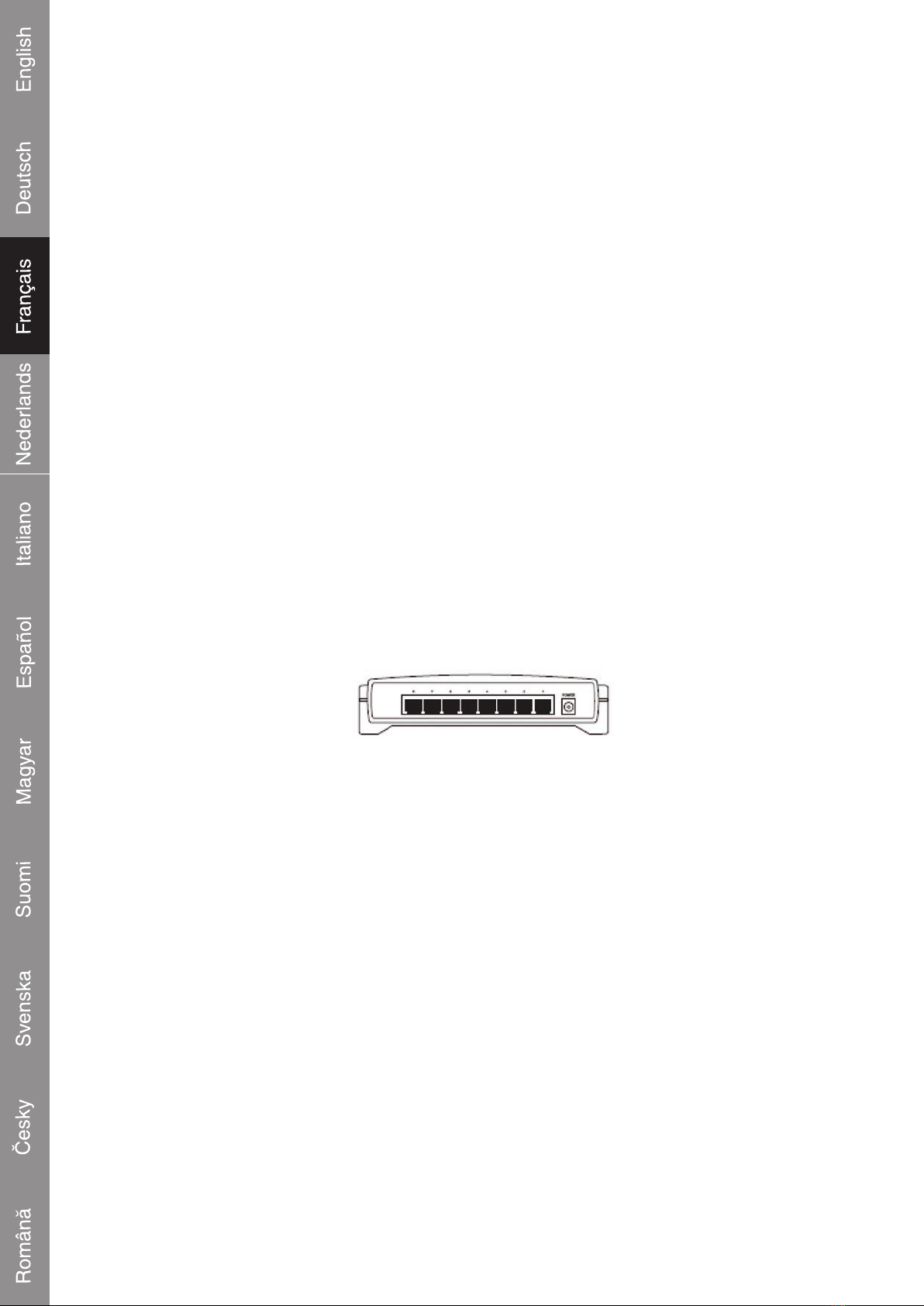
2.2 Rückseite
Die Rückseite des Switch besteht aus 8 (beim CMP-EHUB41 sind es 5 Ports) 10/100/1000 MBit/s
RJ45 Ports und einer Anschlussbuchse für die AC Stromversorgung. Alle Ports können auch als
Uplink-Port verwendet werden.
Abbildung 2-1 CMP-EHUB51 Switch Rückseite Skizze
2.3 LED-Anzeigen
Die LED-Anzeigen beinhalten Power LED und Link/Act LEDs. Die LED-Anzeigen werden für die
Überwachung und Fehlerbehebung des Switch verwendet. Der folgende Abschnitt zeigt die LED-
Anzeigen des Switch zusammen mit einer Erklärung für jede Anzeige.
• Power LED: Diese Anzeige leuchtet rot, wenn der Switch eingeschaltet ist. Wenn die LED nicht
leuchtet, prüfen Sie bitte das Netzteil und die Verbindung.
• 1000M Link/Act LED: Diese Anzeige wird grün leuchten, wenn ein 1000 MBit/s Gerät an den
entsprechenden Port angeschlossen ist. Die Anzeige blinkt, wenn über die Verbindung Daten
übertragen oder empfangen werden.
• 10/100M Link/Act LED: Diese Anzeige wird grün leuchten, wenn ein 10 oder 100 MBit/s Gerät an
den entsprechenden Port angeschlossen ist. Die Anzeige blinkt, wenn über die Verbindung Daten
übertragen oder empfangen werden.

2
Fehlersuche
1. Die Power LED leuchtet nicht
Stellen Sie sicher, dass das AC Netzteil ordnungsgemäß mit einer Steckdose verbunden und der
Steckverbinder in die Anschlussbuchse des Switch gesteckt ist.
Stellen Sie sicher, dass die Stromquelle eingeschaltet ist.
2. Die Link/Act LED leuchtet nicht, wenn ein Gerät an den entsprechenden Port angeschlossen ist
Stellen Sie sicher, dass die Kabelsteckverbinder fest in den Switch und in das Gerät gesteckt sind.
Stellen Sie sicher, dass das angeschlossene Gerät eingeschaltet und dessen Netzteil ordnungsgemäß
installiert und funktionsbereit ist.
Das Kabel darf nicht länger als 100 m sein.
KONFORMITÄTSERKLÄRUNG
Wir,
Nedis B.V.
De Tweeling 28
5215MC ’s-Hertogenbosch
Niederlande
Tel.: 0031 73 599 1055
Email: info@nedis.com
erklären, dass das Produkt:
Name: KÖNIG
Modell: CMP-EHUB41 & 51
Beschreibung: 5 & 8 Port Gigabit Switch
den folgenden Standards entspricht:
EMV: EN 55022: 1998 + A1:2000 + A2:2003 + A2:2006
EN 61000-3-2:2000, EN 61000-3-3: 1995 + A1:2001
EN 55024: 1998 + A1 : 2001 + A2 : 2003
LVD: EN 60950-1: 2001, EN 60950-1: 2006
Befolgt die Vorschriften der EMV-Richtlinie 89/336/EEC und NSR 2006/95/EC.
‘s-Hertogenbosch, Januar 2008
J. Gilad
Einkaufsleiterin

3
Sicherheitsvorkehrungen:
Um das Risiko eines elektrischen Schlags zu verringern, sollte
dieses Produkt AUSSCHLIESSLICH von einem autorisierten
Techniker geöffnet werden, wenn eine Wartung erforderlich ist.
Trennen Sie das Produkt vom Stromnetz und anderen Geräten, wenn ein Problem auftreten sollte.
Sorgen Sie dafür, dass das Gerät nicht mit Wasser oder Feuchtigkeit in Berührung kommt.
Wartung:
Nur mit einem trockenen Tuch säubern. Keine Lösungsmittel oder Schleifmittel verwenden.
Garantie:
Es kann keine Garantie oder Haftung für irgendwelche Änderungen oder Modikationen des Produkts
oder für Schäden übernommen werden, die aufgrund einer nicht ordnungsgemäßen Anwendung
des Produkts entstanden sind.
Allgemein:
Konstruktionen und technische Daten können ohne vorherige Ankündigung geändert werden.
Alle Logos, Marken und Produktnamen sind Warenzeichen oder registrierte Warenzeichen ihrer
jeweiligen Eigentümer und werden hiermit als solche anerkannt.
Achtung:
Dieses Produkt ist mit diesem Symbol gekennzeichnet. Es bedeutet, dass die verwendeten
elektrischen und elektronischen Produkte nicht im allgemeinen Haushaltsmüll entsorgt
werden dürfen. Für diese Produkte stehen gesonderte Sammelsysteme zur Verfügung.
Copyright ©
VORSICHT
STROMSCHLAGGEFAHR
NICHT ÖFFNEN

CMP-EHUB41/51

1
Chapitre 1 : Installation
1.1. Installation
Pour installer le switch, veuillez suivre ces étapes :
1. Vous pouvez placer le switch sur une table plane ou un mur vertical si vous souhaitez le
suspendre.
2. Veuillez contrôler attentivement l'adaptateur secteur et vous assurer qu'il est correctement branché
à une source d'alimentation.
3. Assurez-vous de laisser sufsamment d'espace pour la dissipation de la chaleur et une bonne
ventilation du switch. Ne placez pas d'objets lourds sur le switch.
1.2 Mise sous tension
Après la mise sous tension du switch, il s'initialise automatiquement et les indicateurs à LED doivent
se comporter comme suit :
1. Tous les indicateurs LED Link/Act clignote temporairement au départ, puis en séquence et enn
temporairement pour indiquer la réinitialisation du système.
2. L'indicateur LED Power reste allumé tout le temps.
Chapitre 2 : Identication des composants externes
2.1 Panneau avant
Le panneau avant du switch est composé de plusieurs indicateurs LED.
2.2 Panneau arrière
Le panneau arrière du switch est composé de 8 (ou 5, dans le cas du CMP-EHUB41) ports
10/100/1000Mbps RJ45 et d'un connecteur d'alimentation CA. Tous les ports peuvent fonctionner
comme port Uplink.
Figure 2-1 Aperçu du panneau arrière du switch CMP-EHUB51
2.3 Indicateurs LED
Les indicateurs LED comprennent la LED Power et les LED Link/Act. Les indicateurs à LED sont
utilisés pour la surveillance et le dépannage du switch. La section suivante montre les indicateurs
LED du switch ainsi qu'une explication de chaque indicateur.
• LED Power : Cet indicateur s'allume en rouge lorsque le switch est mis sous tension. Si le LED
ne s'allume pas, veuillez contrôler l'adaptateur secteur et le branchement.
• LED 1000M Link/Act : Cet indicateur s'allume en vert lorsqu'un périphérique 1000Mbps est
branché au port correspondant. Il clignote lorsque des données sont transmises ou reçues sur la
connexion.
• LED 10/100M Link/Act : Cet indicateur s'allume en vert lorsqu'un périphérique 10Mbps ou
100Mbps est branché au port correspondant. Il clignote lorsque des données sont transmises ou
reçues sur la connexion.

2
Dépannage
1. La LED Power ne s'allume pas
Assurez-vous que l'adaptateur secteur est correctement branché dans une prise et que son
connecteur est branché dans la prise d'alimentation du switch.
Assurez-vous que la source d'alimentation est activée.
2. La LED Link/Act ne s'allume pas lorsqu'un périphérique est branché sur le port correspondant
Assurez-vous que les connecteurs du câble sont correctement branchés dans le switch et le
périphérique.
Assurez-vous que le périphérique branché est sous tension et que son adaptateur est installé
correctement et fonctionne.
Le câble doit avoir une longueur inférieure à 100 mètres (328 pieds).
DECLARATION DE CONFORMITE
Nous,
Nedis B.V.
De Tweeling 28
5215MC ’s-Hertogenbosch
Pays Bas
Tel.: 0031 73 599 1055
Email : info@nedis.com
Déclarons que le produit :
Nom : KÖNIG
Modèle : CMP-EHUB41 & 51
Description : switch gigabit 5 & 8 ports
est conforme aux normes suivantes :
CEM : EN 55022: 1998 + A1:2000 + A2:2003 + A2:2006
EN 61000-3-2:2000, EN 61000-3-3: 1995 + A1:2001
EN 55024: 1998 + A1 : 2001 + A2 : 2003
DBT: EN 60950-1: 2001, EN 60950-1: 2006
suivant les dispositions de la directive 89/336/EEC et LVD 2006/95/EC.
‘s-Hertogenbosch, janvier 2008
Mme. J. Gilad
Directeur des Achats

3
Consignes de sécurité :
An de réduire les risques de chocs électriques, ce produit ne
doit être ouvert QUE par un technicien qualié agrée en cas
de réparation. Débranchez l'appareil du secteur et des autres
équipements en cas de problème. N'exposez jamais l'appareil à l'eau ou à l'humidité.
Entretien :
Nettoyez uniquement avec un chiffon sec. N'utilisez pas de solvants ou de produits abrasifs.
Garantie :
Aucune garantie ou responsabilité ne sera acceptée en cas de modication et/ou de transformation
du produit ou en cas de dommages provoqués par une utilisation incorrecte de l'appareil.
Généralités :
Le design et les caractéristiques techniques sont sujets à modication sans notication préalable.
Tous les logos de marques et noms de produits sont des marques déposées ou immatriculées dont
leurs détenteurs sont titulaires et sont donc reconnus comme telles dans ce document.
Attention :
Ce symbole gure sur l'appareil. Il signie que les produits électriques et électroniques ne
doivent pas être jetés avec les déchets domestiques. Le système de collecte est différent
pour ce genre de produits.
Copyright ©
ATTENTION
RISQUE DE CHOC ELECTRIQUE
NE PAS OUVRIR

CMP-EHUB41/51

1
Hoofdstuk 1: Installatie
1.1 Installatie
Voor het installeren van de switch voert u de volgende stappen uit:
1. Plaats de switch op een tafel of bureau. U kunt het apparaat ook verticaal aan een muur o.i.d.
ophangen.
2. Controleer de voedingsadapter zorgvuldig, sluit deze aan op de switch en steek de adapter in een
stopcontact.
3. Houd rond de switch voldoende ruimte vrij voor ventilatie en warmteafgifte van het apparaat.
Plaats geen zware voorwerpen op de switch.
1.2 Inschakelen
Nadat de switch ingeschakeld is, wordt deze automatisch geïnitialiseerd. De indicatie-LED's branden
als volgt:
1. Alle Link/Act-LED's zullen eerst kortstondig oplichten, daarna opeenvolgend knipperen en ten
slotte kortstondig oplichten, hetgeen een reset van het systeem aangeeft.
2. De Power-LED brandt permanent.
Hoofdstuk 2: Indicatie-LED's en aansluitingen
2.1 Voorzijde
De voorzijde van de switch bevat verschillende indicatie-LED's.
2.2 Achterzijde
De achterzijde van de switch bevat acht (in geval van de CMP-EHUB41 vijf poorten) 10/100/1000Mbps
RJ45 poorten en een aansluiting voor de voedingsadapter. Alle poorten kunnen als Uplink poort
werken.
Afbeelding 2-1 Achterzijde van CMP-EHUB51
2.3 Indicatie-LED's
De indicatie-LED's bestaan uit een Power-LED en verscheidene zogenaamde Link/Act-LED's.
De indicatie-LED's dienen ter controle van de switch en het opsporen/oplossen van problemen.
Hieronder vindt een overzicht van de functies van de verschillende indicatie-LED's.
• Power-LED: Deze LED brandt rood wanneer de switch ingeschakeld is. Als de LED niet brandt
controleer dan de voedingsadapter en de aansluiting tussen de voedingsadapter en de switch.
• 1000M Link/Act-LED: Deze LED zal groen branden wanneer er op de corresponderende poort
een 1000Mbps apparaat aangesloten is. De LED knippert wanneer er via de betreffende poort
data verzonden of ontvangen wordt.
• 10/100M Link/Act-LED: Deze LED zal groen branden wanneer er op de corresponderende poort
een 10Mbps of 100Mbps apparaat aangesloten is. De LED knippert wanneer er via de betreffende
poort data verzonden of ontvangen wordt.

2
Het oplossen van problemen
1. De Power-LED brandt niet.
Zorg er voor dat de voedingsadapter op de juiste wijze in een stopcontact zit en dat het stekkertje
van de adapter in de connector van de switch gestoken is.
Controleer of er spanning op het stopcontact staat.
2. De Link/Act-LED brandt niet wanneer er op de corresponderende poort een apparaat aangesloten
is.
Zorg er voor dat de connectors van de verbindingskabels goed in de switch en het apparaat gestoken zijn.
Zorg er voor dat het aangesloten apparaat ingeschakeld is en dat de adapter ervan juist aangesloten
is en werkt.
De kabel moet korter dan 100 meter zijn.
CONFORMITEITVERKLARING
Wij,
Nedis BV
De Tweeling 28
5215 MC ’s-Hertogenbosch
Nederland
Tel.: 0031 73 599 1055
E-mail: info@nedis.com
Verklaren dat het product:
Naam: KÖNIG
Model: CMP-EHUB41 & 51
Omschrijving: 5 & 8 poorten gigabit switch
in overeenstemming met de volgende normen is:
EMC: EN 55022: 1998 + A1:2000 + A2:2003 + A2:2006
EN 61000-3-2:2000, EN 61000-3-3: 1995+A1:2001
EN 55024: 1998 + A1 : 2001 + A2 : 2003
LVD: EN 60950-1: 2001, EN 60950-1: 2006
Volgens de bepalingen van EMC richtlijn 89/336/EEC en LVD 2006/95/EC.
‘s-Hertogenbosch, januari 2008
Mevr. J. Gilad
Directeur inkoop

3
Veiligheidsvoorzorgsmaatregelen:
Wanneer service of reparatie noodzakelijk is, mag dit product
UITSLUITEND door een geautoriseerde technicus geopend
worden; dit om de kans op het krijgen van een elektrische
schok te voorkomen. Als er een probleem optreedt, koppel het product dan los van het lichtnet en
van andere apparatuur. Stel het product niet bloot aan water of vocht.
Onderhoud:
Uitsluitend reinigen met een droge doek. Gebruik geen reinigingsmiddelen of schuurmiddelen.
Garantie:
Voor wijzigingen en veranderingen aan het product of schade veroorzaakt door een verkeerd
gebruik van dit product, kan geen aansprakelijkheid worden geaccepteerd. Tevens vervalt daardoor
de garantie.
Algemeen:
Wijziging van ontwerp en specicaties zonder voorafgaande mededeling onder voorbehoud.
Alle logo's, merken en productnamen zijn handelsmerken of geregistreerde handelsmerken van de
respectievelijke eigenaren en worden hierbij als zodanig erkend.
Let op:
Dit product is voorzien van dit symbool. Dit symbool geeft aan dat afgedankte elektrische
en elektronische producten niet met het gewone huisafval verwijderd mogen worden. Voor
dit soort producten zijn er speciale inzamelingspunten.
Copyright ©
LET OP:
GEVAAR VOOR ELEKTRISCHE
SCHOK - NIET OPENEN

CMP-EHUB41/51

1
Caitolo 1: Installazione
1.1 Installazione
Per installare l'interruttore seguire i seguenti punti:
1. L'interruttore può essere collocato su una supercie piana oppure appeso ad un muro.
2. Controllare con cura l'adattatore di alimentazione assicurandosi di averlo ben collegato
all'alimentazione.
3. Accertarsi di avere lasciato spazio sufciente per assicurare all'interruttore la dispersione del
calore e una buona ventilazione. Non collocare oggetti pesanti sull'interruttore.
1.2 Alimentazione accesa
Una volta alimentato, l'interruttore verrà automaticamente inizializzato e gli indicatori LED dovrebbero
rispondere nel modo seguente:
1. Tutti gli indicatori LED Link/Act lampeggiano dapprima in modo temporaneo, poi in sequenza ed
inne di nuovo in modo temporaneo, il che indica un resettaggio del sistema.
2. L'indicatore LED dell'alimentazione rimane sempre acceso.
Capitolo 2: Identicazione di componenti esterni
2.1 Pannello anteriore
Il pannello anteriore dell'interruttore è composto da diversi indicatori LED.
2.2 Pannello posteriore
Il pannello posteriore dell'interruttore è composto da 8 porte 10/100/1000Mbps RJ45 (nel caso di
CMP-EHUB41 5 porte) ed una presa di alimentazione. Tutte le porte possono funzionare come porta
Uplink.
Figura 2-1 CMP-EHUB51 Bozza pannello posteriore interruttore
2.3 Indicatori LED
Gli indicatori LED comprendono il LED di alimentazione ed i LED di collegamento/attività. Gli indicatori
LED sono impiegati per il monitoraggio e la risoluzione dei problemi dell'interruttore. La sezione
seguente illustra nel dettaglio ciascun indicatore LED dell'interruttore.
• LED di alimentazione: L'indicatore rosso si accende all'alimentazione dell'interruttore. Se il LED
è spento vericare l'adattatore di alimentazione e il collegamento.
• LED di collegamento/attività 1000M: L'indicatore verde si accende quando un dispositivo a
1000Mbps viene collegato alla relativa porta. Lampeggia quando vengono tramessi o ricevuti dati
dal collegamento.
• LED di collegamento/attività 10/100M: L'indicatore verde si accende quando un dispositivo a
10Mbps o 1000Mbps viene collegato alla relativa porta. Lampeggia quando vengono tramessi o
ricevuti dati dal collegamento.

2
Risoluzione dei problemi
1. Il LED di alimentazione non si accende
Assicurarsi che l'adattatore di alimentazione sia collegato correttamente alla presa e che il relativo
connettore sia bene inserito nel jack di alimentazione dell'interruttore.
Assicurarsi che l'alimentazione sia accesa.
2. Il LED di collegamento/attività non si accende quando un dispositivo viene collegato alla relativa
porta.
Assicurarsi che i connettori cavi siano bene inseriti nell'interruttore e nel dispositivo.
Assicurarsi che il dispositivo collegato sia acceso e che l'adattatore sia correttamente installato e
funzionante.
Il cavo deve avere una lunghezza inferiore ai 100 metri.
DICHIARAZIONE DI CONFORMITÀ
Questa società,
Nedis B.V.
De Tweeling 28
5215MC ’s-Hertogenbosch
Paesi Bassi
Tel.: 0031 73 599 1055
Email: info@nedis.com
Dichiara che il prodotto:
Nome: KÖNIG
Modello: CMP-EHUB41 & 51
Descrizione: 5 & 8 port gigabit switch
è conforme ai seguenti standard
EMC: EN 55022: 1998 + A1:2000 + A2:2003 + A2:2006
EN 61000-3-2:2000, EN 61000-3-3: 1995 + A1:2001
EN 55024: 1998 + A1 : 2001 + A2: 2003
LVD: EN 60950-1: 2001, EN 60950-1: 2006
Secondo le disposizioni della direttiva EMC CEE89/336 and LVD CEE2006/95.
‘s-Hertogenbosch, Gennaio 2008
Sig.ra J. Gilad
Direttore agli acquisti

3
Precauzioni di sicurezza:
Per ridurre il rischio di scosse elettriche, questo prodotto
deve essere aperto ESCLUSIVAMENTE da personale tecnico
specializzato, se occorre assistenza. Se si dovessero vericare
dei problemi, scollegare il prodotto dall'alimentazione di rete e da ogni altra apparecchiatura. Non
esporre il prodotto ad acqua o umidità.
Manutenzione:
Pulire solo con un panno asciutto. Non utilizzare solventi detergenti o abrasivi.
Garanzia:
Non sarà accettata alcuna garanzia o responsabilità in relazione a cambiamenti e modiche del
prodotto o a danni determinati dall'uso non corretto del prodotto stesso.
Generalità:
Il design e le caratteristiche tecniche sono soggetti a modica senza necessità di preavviso.
Tutti i logo, i marchi e i nomi dei prodotti sono marchi registrati dei rispettivi proprietari e riconosciuti
come tali.
Attenzione:
Il prodotto è contrassegnato con questo simbolo, con il quale si indica che i prodotti elettrici
ed elettronici usati non devono essere gettati insieme ai riuti domestici. Per questi prodotti
esiste un sistema di raccolta differenziata.
Copyright ©
ATTENZIONE
RISCHIO DI SCOSSE ELETTRICHE
NON APRIRE
This manual suits for next models
3
Table of contents
Languages:
Other Konig Switch manuals

Konig
Konig CMP-KVMSWIT20 User manual

Konig
Konig CMP-EHUB52 User manual

Konig
Konig CMP-KVMSWIT70 User manual

Konig
Konig CMP-KVMSWIT60 User manual

Konig
Konig CMP-KVMSWIT75 User manual

Konig
Konig CMP-KVMSWIT50 User manual

Konig
Konig CMP-USBNETBOX4 User manual

Konig
Konig KN-HDMISW25 User manual

Konig
Konig KN-HDMISW10 User manual

Konig
Konig KN-HDMISW02 User manual