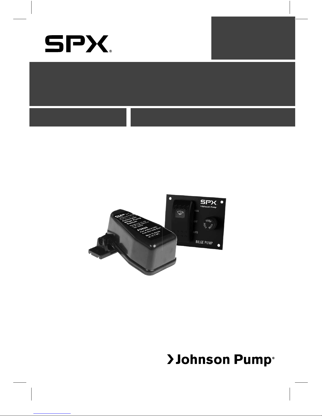
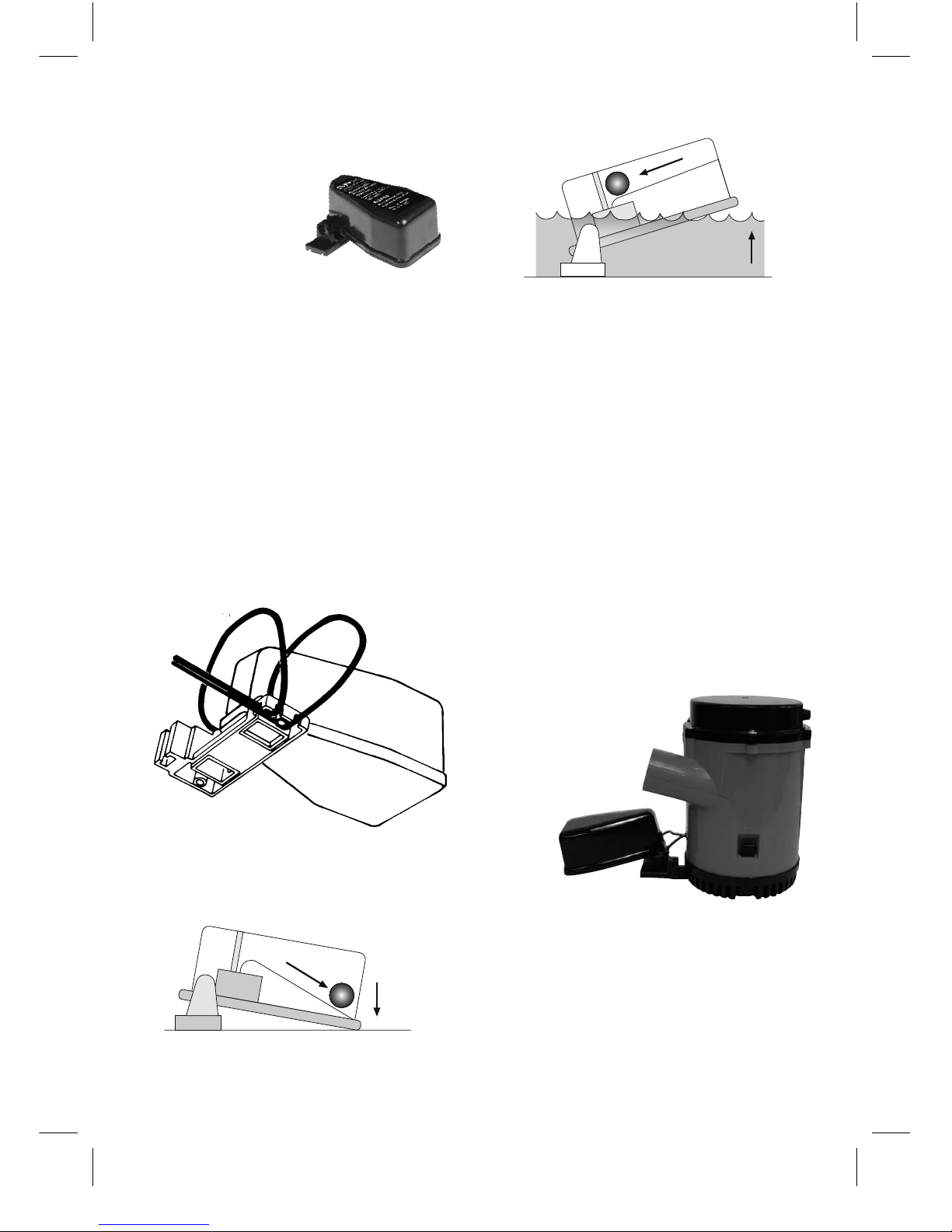
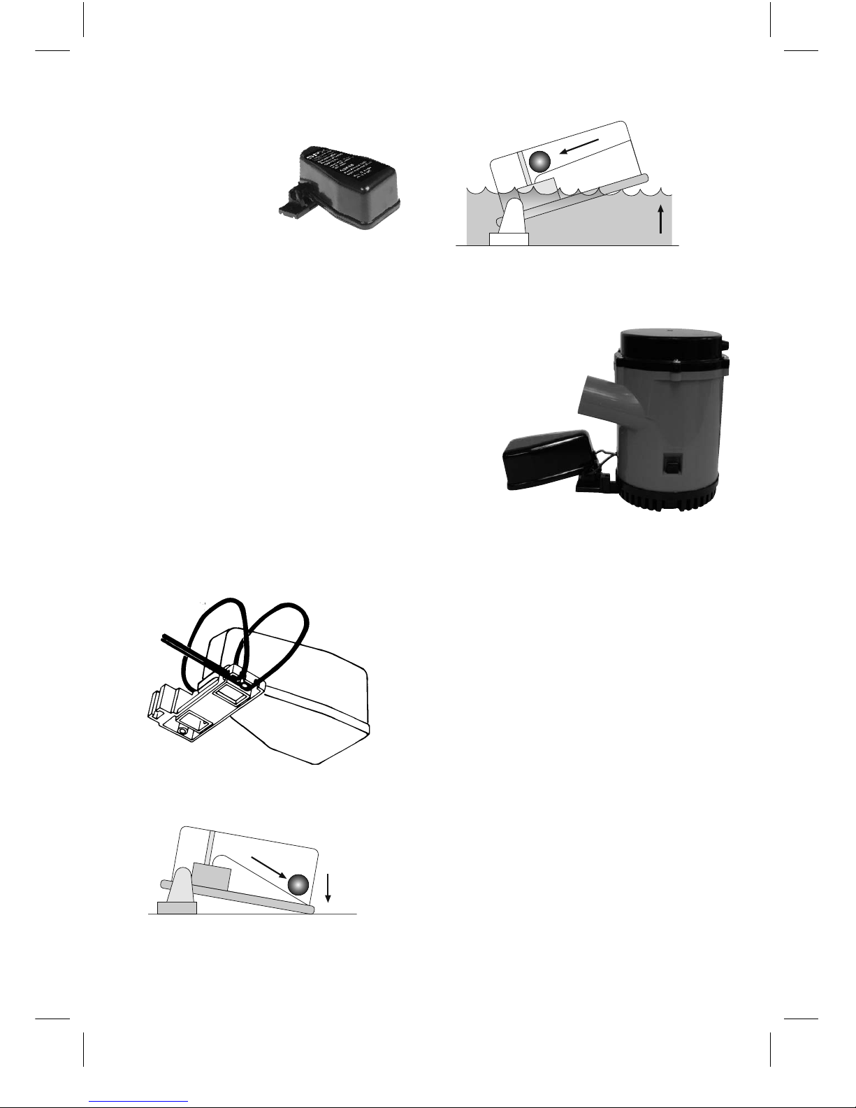
Automatic Switch
Made in China
ISO8846:1990/electrical devices-Protection against ignition of surrounding flammable gases
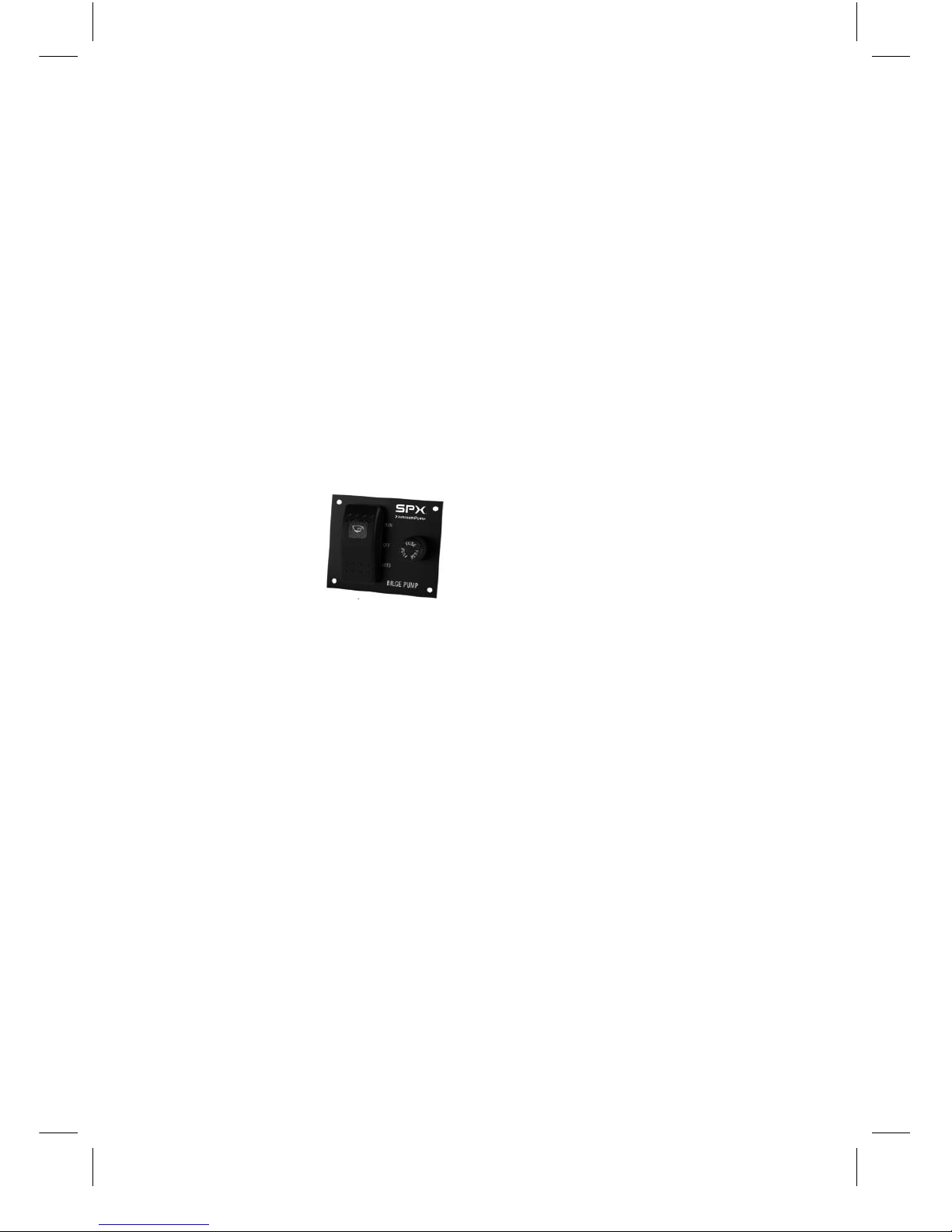
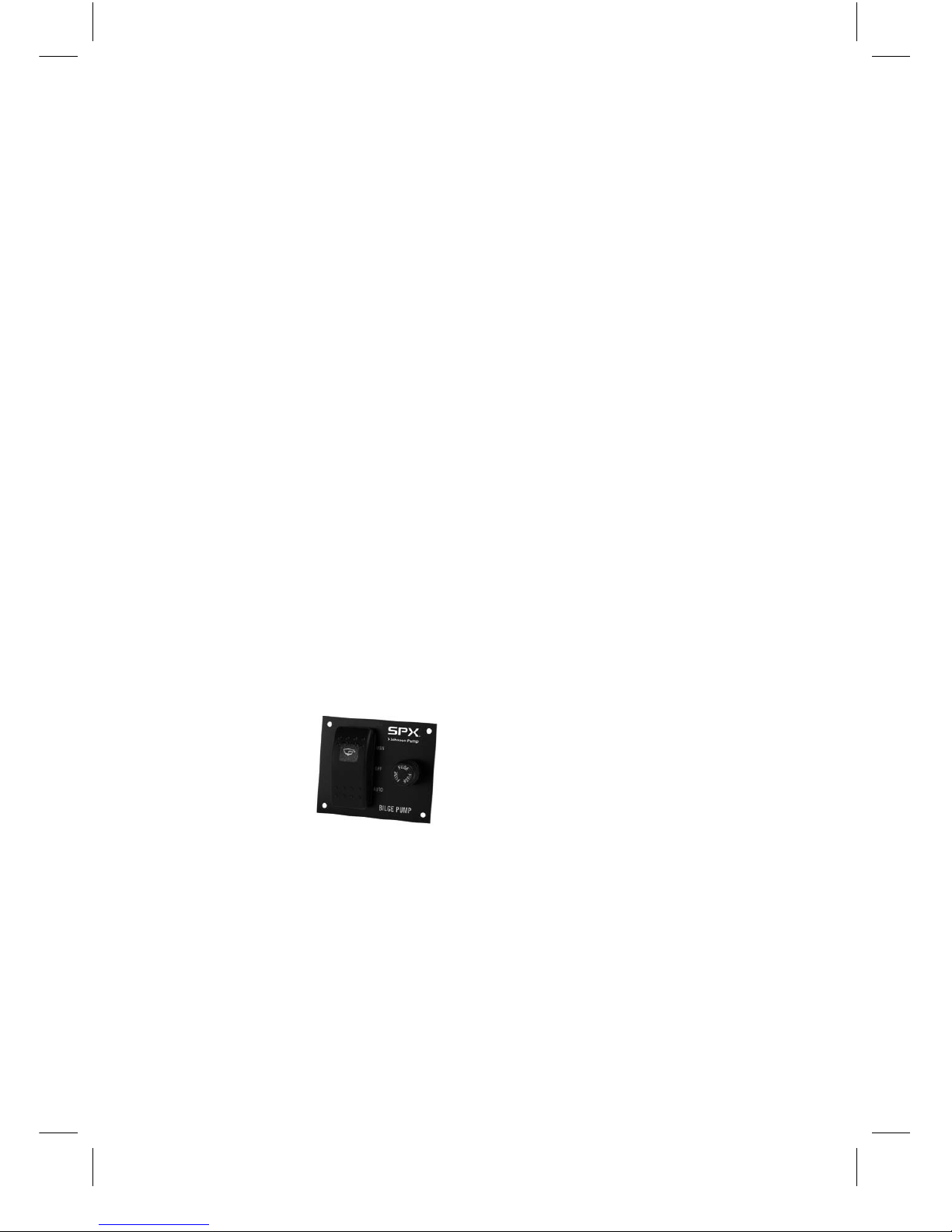
Bilge Pump Control Panel
Made in USA
Garanti 1 år
Warranty 1 year
Garantie 1 Jahr
Garantie 1 an
Garanzia 1 anno
Garantía 1 año
INDEX INDICE
Svenska....................................................................................................................................................................3
English .....................................................................................................................................................................5
Deutsch....................................................................................................................................................................7
Français ...................................................................................................................................................................9
Español ................................................................................................................................................................11
Italiano ................................................................................................................................................................... 13
Besök www.johnson-pump.com för mer information om vår världsomspännande organisation, våra godkännanden,
certifieringar och lokala representanter. SPX Corporation förbehåller sig rätten att ändra design och material utan
föregående avisering. Designelement, konstruktionsmaterial och dimensioner som beskrivs i denna bulletin gäller
endast som information och skall alltid bekräftas skriftligt för att vara gällande.
For more information about our worldwide locations, approvals, certifications, and local representatives, please visit
www.johnson-pump.com. SPX Corporation reserves the right to incorporate our latest design and material changes
without notice or obligation. Design features, materials of construction and dimensional data, as described in this
bulletin, are provided for your information only and should not be relied upon unless confirmed in writing.
Für weitere Informationen über unsere weltweiten Standorte, Zulassungen, Zertifizierungen und unsere Vertreter vor
Ort, besuchen Sie bitte unsere Webseite: www.johnson-pump.com. Die SPX Corporation behält sich das Recht vor,
die neuesten Konstruktions- und Werkstoffänderungen ohne vorherige Ankündigung und ohne Verpflichtung hierzu
einfließen zu lassen. Konstruktive Ausgestaltungen, Werkstoffe sowie Maßangaben, wie sie in dieser Mitteilung
beschrieben sind, sind nur zur Information. Alle Angaben sind unverbindlich, es sei denn, sie wurden schriftlich
bestätigt.
Pour plus d’information sur nos succursales internationales, nos approbations, nos certifications et nos représentants
locaux, veuillez consulter notre site Internet au www.johnson-pump.com. SPX Corporation se réserve le droit
d’incorporer nos plus récents concepts ainsi que tout autre modification importante sans préavis ou obligation. Les
éléments décoratifs, matériaux de construction et les données dimensionnelles, tels qu’énoncés dans ce communiqué,
sont fournis pour votre information seulement et ne doivent pas être considérés comme officiels à moins d’avis
contraire par écrit.
Para más información sobre nuestras oficinas a nivel mundial, aprobaciones, certificaciones y representantes locales,
por favor visite www.johnson-pump.com. SPX Corporation se reserva el derecho de incorporar nuestro diseño más
reciente y cambios materiales sin necesidad de notificación previa u obligación de ningún tipo. Características de
diseño, materiales de construcción y dimensiones, tal y como están descritas en este boletín, son proporcionadas sólo
con fines informativos y no deben ser usados como referencia a menos que sean confirmados por escrito.
Per ottenere maggiori informazioni sulle nostre sedi nel mondo, autorizzazioni, certificazioni, e rappresentanti locali,
potete visitare il sito www.johnson-pump.com. La SPX Corporation si riserva il diritto di apportare cambiamenti ai
propri design e materiali senza preavviso o vincolo. Le caratteristiche del design, i materiali di costruzione e i dati
dimensionali, così come descritti nel presente bollettino, sono forniti solo per vostra informazione e non saranno
oggetto di obbligazione salvo autorizzazione confermata per iscritto.