FibroLAN GSM1000 Manual

GSM1000&GSM1000/MA Series
1000Base-SX/LX to 1000Base-LX
NTU/ Extender
User and Installation Guide
Version: 3.0
FibroLAN Ltd.
2 Carmel St. P.O. Box 544 Yokneam-Illit, 20692 ISRAEL
Tel: 972-4-9591717 Fax: 972-4-9591718

GSM1000 Gigabit Converter
2
FEDERAL COMMUNICATIONS COMMISSION
AND
CANADIAN DEPARTMENT OF COMMUNICATIONS
RADIO FREQUENCY INTERFERENCE STATEMENTS
This equipment generates, uses, and can radiate radio frequency energy and if
not installed and used properly, that is, in strict accordance with the
manufacturer’s instructions, may cause interference to radio communication. It
has been tested and found to comply with the limits for a Class A computing
device in accordance with the specifications in Subpart B of Part 15 of FCC
rules, which are designed to provide reasonable protection against such
interference when the equipment is operated in a commercial environment.
Operation of this equipment in a residential area is likely to cause interference,
in which case the user at his own expense will be required to take whatever
measures may be necessary to correct the interference.
Changes or modifications not expressly approved by the party responsible for
compliance could void the user’s authority to operate the equipment.
This digital apparatus does not exceed the Class A limits for radio noise
emission from digital apparatus set out in the Radio Interference Regulation of
the Canadian Department of Communications.
Le présent appareil numérique n’émet pas de bruits radioélectriques dépassant les limites
applicables aux appareils numériques de la classe A prescrites dans le Règlement sur le
brouillage radioélectrique publié par le ministère des Communications du Canada.
CE Mark
The CE mark symbolizes compliance with the European Community
required technical standards.
The product herewith complies with the requirements of the EMC Directive
89/336/EEC, the Low Voltage Directive 73/23/EEC and the R&TTE
Directive 99/5/EC.
The product was tested in a typical configuration.
Levy Malkiely
Quality Manager

GSM1000 Gigabit Converter
3
Table of contents
General Description page 4
Product description page 5
Front Panel components page 7
Installation procedures page 8
Power connection page 9
Fiber Optic connectivity page 10
Fiber ports specifications page 11
DIP switches setting page 12
LST (Link Segmentation Test) page 13
MA™ Concepts and Functions page 15
SLE (Subscriber Link Emulation) page 16
Typical Configurations page 17
Default Parameters setting page 19
Troubleshooting page 20
Specifications page 21
Warranty Limitation page 22
Thank you for purchasing the GSM1000/GSM1000MA GBE
Media Converter from FibroLAN.
We hope that this guide will help you to obtain the
best results from the device while minimizing
installation time.
If you still need help installing or troubleshooting the GSM1000 converter
after reading the detailed information in this guide, please visit our web
site, contact your reseller, or call FibroLAN directly.
Note: unless where indicated otherwise, in this guide, the GSM1000
applies also to GSM1001 through GSM1021, and to similar
GSM1000/MA devices. Single Fiber Strand devices are also available
TRADEMARKS
HP and OpenView are registered trademarks of Hewlett-Packard.
Any other trademarks mentioned in this manual are acknowledged to be the property of
the trademark owners.

GSM1000 Gigabit Converter
4
1 – General Description
The GSM1000 Media Converter extends the distance of your LAN by converting a gigabit
Multimode (or Single Mode) into a GBE Single Mode signal transmission.
The device provides conversion from a MM (1000Base-SX) or SM (1000Base-LX) into a SM
(1000Base-LX) link allowing distance gain of up to120Km.
The GSM1000 through 1003 are suitable for point-to-point connectivity, whereas the GSM1004
-1009, GSM1016, GSM1018, GSM1020, and GSM1021 models allow extension, including
cascading long haul networks.
The GSM1000/MA&GSM1010/MA are another GSM1000 family products (remotely managed
devices) supporting the FibroLAN management MA™ technology.
Single Fiber Strand GSM1000 (20Km) and GSM1000/MA (20,40Km) are also available
The MA™ (Micro Agent) is an on chip management system enabling the management of remote
access devices, eliminating the need of a SNMP agent and IP address.
When the GSM1000/MA is connected through its F/O link to a remote Master Unit
(Access Concentrator normally located on the Access Node or Network Center) which is MA™
enabled and SNMP managed (FibroLAN Metrostar™, or S.CON1M/MA), a comprehensive set of
monitoring and control functions can be implemented from any management station (normally
located in the Master Unit) into the attached remote units (GSM1000/MA) or any FibroLAN
device supporting the MA™ technology.
Link Segmentation Test (LST) allows easy link test segmentation (inTest mode)
to locate a failed link segment, and in Fault Propagation mode (LST OFF) the disconnect of the
entire link segment ( if one of the F/O link is disrupted) and Network Device notification of the
link failure. A front panel LED will show the LST setting for each F/O port.
The GSM1000 family supports another unique outstanding feature: SLE
(Subscriber Link Emulation) enabled through system management for GSM
enabled MA devices (GSM1000/MA and GSM1010/MA, refer to section 11 for details)
A Loop-Back mechanism on each F/O port simplifies troubleshooting during link problems.
2 – Features Summary
•Two fiber (1000Base-SX/UNI,1000Base-LX/OA) ports
•Conversion method: Direct Digital with LST capability.
•MTU: 10K octets
•Covered distance: up to 120Km point to point, more if cascaded.
•LST: Link Segmentation Test for each port
•Local loop-back for each F/O port
•Optional internal DC Power Supply (-48VDC)
•Versatile installation: desktop, shelf or wall-mount
•Diagnostics LED indicators for Link and Activity monitoring each F/O
port.
•Optional Extended Temperature Range (ETR)
•Front Panel DIP switches for LB (loop-back) and LST for each F/O port.
•Front panel MA Active LED (GSM1000/MA&GSM1010/MA series).
•Remote MA management (GSM1000/MA&GSM1010/MA series).
•"Remote Power Failure" signal is generated when the GSM1000MA
device senses a power failure
•Supports SLE (Subscriber Link Emulation) through system management
(GSM1000/MA&GSM1010/MA devices).

GSM1000 Gigabit Converter
5
3 – Product Description
The GSM devices are offered in the following preconfigured versions as shown
in the below tables:
GSM1000 1000Base-SX, Duplex SC, Multi Mode 850nm (up to 550m) to 1000Base-LX, Duplex SC, Single
Mode 1310nm, 10km
GSM1001 1000Base-SX, Duplex SC, Multi Mode 850nm (up to 550m) to 1000Base-LX, Duplex SC,
Single Mode 1310nm, 20km
GSM1002 1000Base-SX, Duplex SC, Multi Mode 850nm (up to 550m) to 1000Base-LX, Duplex SC,
Single Mode 1550nmDFB, 40km
GSM1003 1000Base-SX, Duplex SC, Multi Mode 850nm (up to 550m) to 1000Base-LX, Duplex SC,
Single Mode 1550nmDFB, 80km
GSM1020 1000Base-SX, Duplex SC, Multi Mode 850nm (up to 550m) to 1000Base-LX, Duplex SC,
Single Mode 1550nm/DFB/APD, 120km
GSM1004 1000Base-LX extender, Single Mode 1310nm, Duplex SC, 10km to Single Mode 1310nm,
Duplex SC, 10km
GSM1005 1000Base-LX extender, Single Mode 1310nm, Duplex SC, 20km to Single Mode 1310nm,
Duplex SC, 20km
GSM1006 1000Base-LX extender, Single Mode 1550nm DFB, Duplex SC, 40km to Single Mode
1550nm DFB, Duplex SC, 40km
GSM1007 1000Base-LX extender, Single Mode 1550nm DFB, Duplex SC, 80km to Single Mode
1550nm DFB, Duplex SC, 80km
GSM1021 1000Base-LX extender, Single Mode 1550nm DFB-APD, Duplex SC, 120km
to Single Mode 1550nm DFB, Duplex SC, 80km
GSM1018 1000Base-LX extender, Single Mode 1550nm DFB-APD, Duplex SC, 120km
to Single Mode 1550nm (DFB-APD), Duplex SC, 120km
GSM1008 1000Base-LX extender, Single Mode1310nm, Duplex SC, 10km to Single Mode1550nm,
DFB, Duplex SC, 40km
GSM1009 1000Base-LX extender, Single Mode1310nm, Duplex SC, 10km to Single
Mode1310nm, Duplex SC, 20km
GSM1016 1000Base-LX extender, Single Mode1310nm, Duplex SC, 10km to Single Mode
1550nmDFB, Duplex SC, 80km
GSM1000F13 1000Base-SX, SC, Multi Mode 850nm to 1000Base-LX, Simplex SC, Single Mode,
Single Fiber Strand, 1310nm Tx/1550nm Rx, 20Km (over G.652 fiber)
GSM1000F15 1000Base-SX, SC, Multi Mode 850nm to 1000Base-LX, Simplex SC, Single Mode,
Single Fiber Strand, 1550nmDFBTx/1310nm Rx, 20Km (over G.652 fiber)
GSM1000/MA MA Managed 1000Base-SX, Duplex SC, Multi Mode 850nm to 1000Base-LX, Duplex SC,
Single Mode 1310nm, 10km
GSM1001/MA MA Managed 1000Base-SX, Duplex SC, Multi Mode 850nm to 1000Base-LX, Duplex SC,
Single Mode 1310nm, 20km (over G.652 fiber)
GSM1001/MA-48 MA Managed 1000Base-SX, Duplex SC, Multi Mode 850nm to 1000Base-LX, Duplex SC,
Single Mode 1310nm, 20km (over G.652 fiber), -48VDC PSU, including 3m power cable
GSM1002/MA MA Managed 1000Base-SX, Duplex SC, Multi Mode 850nm to 1000Base-LX, Duplex SC,
Single Mode 1550nmDFB, 40km
GSM1003/MA MA Managed 1000Base-SX, Duplex SC, Multi Mode 850nm to 1000Base-LX, Duplex SC,
Single Mode 1550nmDFB, 80km
GSM1003/MA-48 MA Managed 1000Base-SX, Duplex SC, Multi Mode 850nm to 1000Base-LX, Duplex SC,
Single Mode 1550nmDFB, 80km, 48VDC PSU, including 3m power cable
GSM1020/MA Ma managed 1000Base-SX, MM 850nm, 2*SC, to 1000Base-LX, 2*SC, SM, 1550nm
DFB/APD, 120kM
GSM1021/MA MA Managed 1000Base-LX extender, single-mode 1550nm DFB-APD, 120km to
single-mode 1550nm DFB, SC, 80km
GSM1004/MA MA Managed 1000Base-LX extender, single-mode 1310nm, Duplex SC, 10km to single-
mode1310nm, Duplex SC, 10km
GSM1005/MA MA Managed 1000Base-LX extender, Single Mode1310nm, SC, 20km to Single
Mode1310nm, SC, 20km (over G.652 fiber)

GSM1000 Gigabit Converter
6
GSM1006/MA MA Managed 1000Base-LX extender, Single Mode 1550nm DFB, SC, 40km to Single
Mode1550nm DFB, SC, 40km
GSM1007/MA MA Managed 1000Base-LX extender, Single Mode 1550nm DFB, SC, 80km
to Single Mode 1550nm DFB, SC, 80km
GSM1018/MA MA Managed 1000Base-LX extender, Single Mode 1550nm DFB/APD, duplex SC,
120km to Single Mode 1550nm DFB/APD, duplex SC, 120km
GSM1008/MA MA Managed 1000Base-LX extender, Single Mode 1310nm, SC, 10km to Single
Mode1550nm, DFB, SC, 40km
GSM1009/MA MA Managed 1000Base-LX extender, Single Mode 1310nm, SC, 10km to Single Mode
1310nm SC, 20km
GSM1009/MA-48 MA Managed 1000Base-LX extender, Single Mode 1310nm, SC, 10km to Single Mode
1310nm SC, 20km, (over G.652 fiber), -48VDC PSU, including 3m power cable
GSM1016/MA MA managed,1000Base-LX extender, SM, 1310nm, duplex SC, 10Km, to SM, 1550nm DFB,
duplex SC, 80Km
GSM1016/MA-48 MA managed,1000Base-LX extender, SM, 1310nm, duplex SC, 10Km, to SM, 1550nm DFB,
duplex SC, 80Km, 48VDC PSU, including 3m power cable
GSM1000F13/MA MA Managed 1000Base-SX, Duplex SC, Multi Mode 850nm to 1000Base-LX, Simplex SC,
Single Mode, Single Fiber Strand, 1310nm Tx / 1550nm Rx, 20Km (over G.652 fiber)
GSM1000F15/MA MA Managed 1000Base-SX,Duplex SC, Multi Mode 850nm to 1000Base-LX, Simplex SC,
Single Mode, Single Fiber Strand, 1550nmDFB TX / 1310nm Rx, 20km (over G.652)
GSM1000F13L/MA MA Managed 1000Base-SX, Duplex SC, Multi Mode 850nm to 1000Base-LX, Simplex SC,
Single Mode, Single Fiber Strand, 1310nmDFB Tx / 1550nm Rx, 40Km (over G.652 fiber)
GSM1000F15L/MA MA Managed 1000Base-SX, Duplex SC, Multi Mode 850nm to 1000Base-LX, Simplex SC,
Single Mode, Single Fiber Strand, 1550nm DFB TX / 1310nm Rx, 40km (over G.652)
All GSM1000 series models have common basic functionalities. Therefore, any
description and features of one model refers to all other types.
The F/O ports (Port 1=SX/LX, Port 2=LX) support GBE 1000Base-SX/LX transmissions
and are set to FDX (Full Duplex) mode. When the remote device is a FibroLAN
module, you have to ensure that the links connecting the MCM1000T/MCM1000S/L
modules and GSM1000/MA are set to 1000Base-LX Full Duplex to preserve the link
integrity for the MA in - band management.
Any network device that connects to the GSM1000 and GSM1000/MA F/O ports
should be configured to Auto-Negotiation disabled mode (forced to 1000Mbps
and FDX).
The GSM1000 series unit has front panel DIP switches (LST ON/OFF, Loop-Back
ON/OFF) per port to easily perform troubleshooting and maintenance functions.
The device is housed in a compact and rugged metal case, providing strong free –air-
cooling for extended stable operation and reliability.
The GSM1000 series unit is suitable for desktop, shelf (with the optimal CTF- RM) or
wall-mount installation (SCH-WM kit)
The GSM1000 device is equipped with a single internal power supply (100 - 240V
universal input), or an optional -48 VDC power supply (PS48) highly overrated to
increase the system’s MTBF. A front panel LED indicates the power status.
The ETR (Extended Temperature Range) option allows usage in industrial
environment.
The GSM1000/MA series are managed by the FibroLAN MetroView Element
Manager System. These devices generate a "Remote Power Failure" signal upon
power drop. This failure is indicated in the attached GBE module status (Remote
device Power "fail")
GSM1000 Gigabit Converter
7
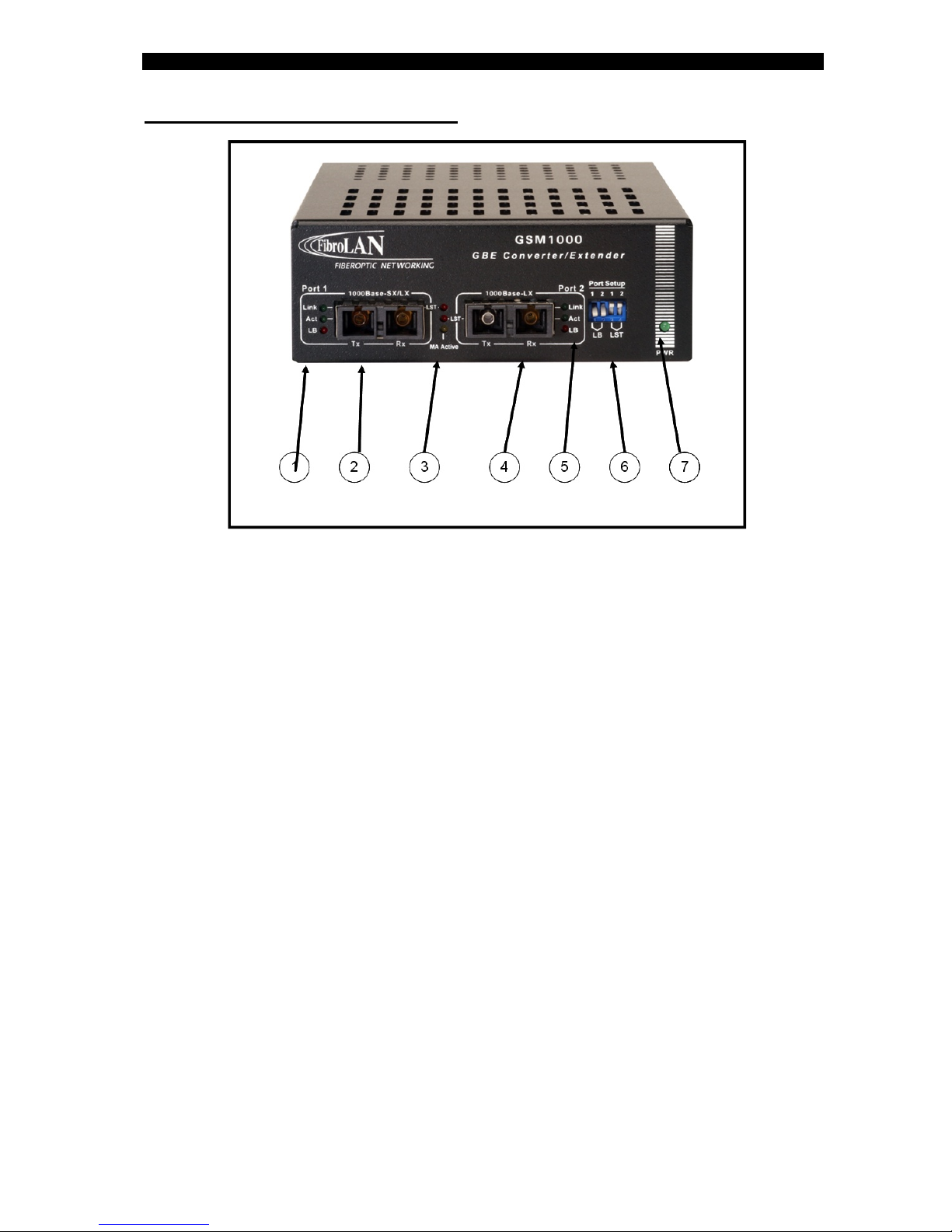
4 – Front Panel components
1. Port 1 (1000Base-SX/LX) LEDs:
•Link: steady green lit: a F/O link has been established.
•Act: port 1 activity. Blinking green (receive / transmit)
•LB: lit (red) implies port 1 is in loop-back mode
2. Port 1/UNI Duplex SC F/O connector: (left /Tx, right / Rx)
3. System LED indicators:
•Upper LED LST: lit red implies a signal is sent from port 2>port 1 in LST ON
mode (DIP switch S4 in UP position) when data is not transmitted at the
same time
•Lower LED LST: lit red implies a signal is sent from port 1 >port 2 in LST ON
mode (DIP switch S3 in UP position) when data is not transmitted at the
same time
•MA active: steady lit (yellow): the GSM1000/MA is connected to a remote
MA enabled and active device.
4. Port 2/OA Duplex SC F/O connector: (left /TX, right / Rx)
5. Port 2 (1000Base-LX) LEDs:
•Link: steady green lit: a F/O link has been established.
•Act: port 1 activity. Blinking green (receive / transmit)
•LB: lit red implies port 2 is in loop-back mode
6. DIP switches LB and LST for each F/O port (see section 9 for details)
DIP switches are shown in their default setting)
7. PWR: Power ON/OFF green LED indicator.

GSM1000 Gigabit Converter
8
5 – Installation procedures
The device is intended for use with indoors power lines only
GSM1000 all models (including –48 VDC models):
For Desktop use: Affix the supplied plastic “feet” (after peeling off the adhesive
protecting sheet) to the bottom of the devices, with each “foot” approximately 1 cm
from each edge. Place the device horizontally on a hard, clean surface (desk, shelf,
etc.), leaving free space around it for natural ventilation. Avoid placing the device on
other active, heat generating equipment and avoid placing such devices on the
GSM1000.
For wall mount installation
Attach the single channel wall mount kit (SCH – WM part # B161) with two (supplied) screws to
the base of the GSM1000 unit (select any 2 adjacent nuts: 1+2 or 3+4 or1+3 or 2+4) to achieve
the desired mode of mounting. The screws to be fixed on the wall should not protrude more
than 8mm. Append the GSM1000 unit on the wall.
For Shelf installation:
Use the 19” Rack shelf (CTF-RM P/N B012) for installation of up to 3 GSM units.
During the installation of several 19” Rack shelves, it is recommended to leave at least
1cm ventilation space between two adjacent racks.
GSM1000 Gigabit Converter
9
6– Power Connection
CAUTION: When connecting a device to an AC (DC) power outlet,
always first connect the cord to the device, and ensure that it is
securely fastened. Only afterward connect the cord to the wall outlet.
Make sure to use grounded (3 way) outlets (in case of AC models).
For each country FibroLAN (or FibroLAN’s distributor) provide with the
product an appropriate power supply cord which is safety approved in
accordance with related country’s National Electric Code
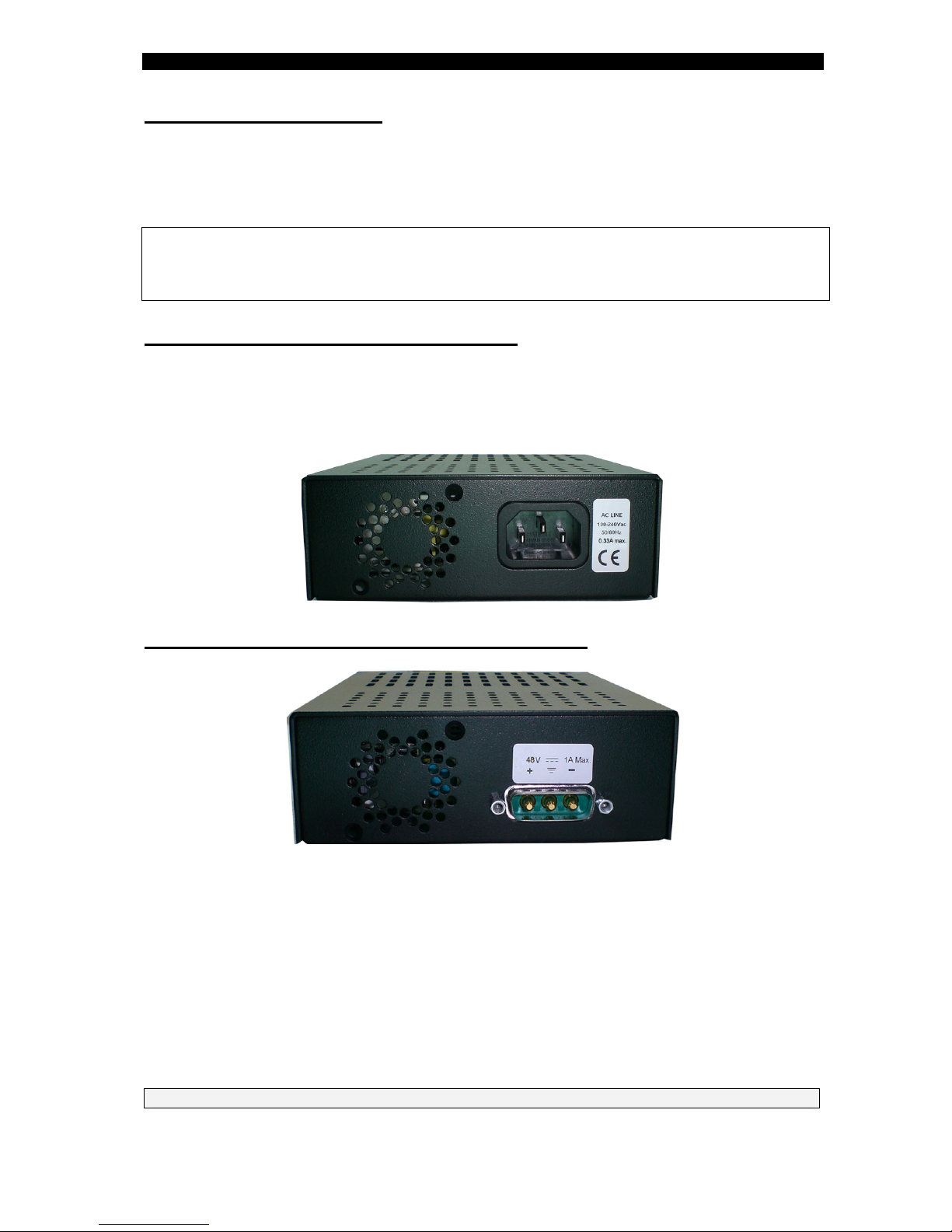
GSM1000 ( all models ) AC connection
Connect to AC line socket at the rear of the converter, using the included power cord.
The GSM1000 will accept and automatically switch between any line voltage from
100 to 240 VAC, 50-60 Hz. There is no ON/OFF switch on the device. When the power
is connected to the device, the device is ON. The POWER LED on the front panel
being illuminated will indicate this.
GSM1000 with 48 VDC Power Supply ( PS48 )
Proceed as above using a suitable DC supply cable. Verify that the DC-Mains
provide a 10Amp DC circuit breaker. Ensure that the polarity of the cable complies
with the polarity of the DC receptacle on the device as depicted above. If you use the
FibroLAN CBPS-48V cable (B151), insert all-way-in the D-type DC connector and
secure the D-Shell to the DC Inlet of the GSM1000 device using the two captive
screws. Connect the cable 3 leads to the DC Power Outlet, ensuring that the -48V blue
lead is connected to the -48V of the DC Power Outlet, the red/brown OV lead to the OV
of the DC Power Outlet, and the ground lead (yellow/green) to the ground of the DC
Power Outlet. There is no ON/OFF switch on the device.
When the power is connected to the device, the device is ON. The POWER LED being
illuminated will indicate this.
NEVER OPEN THE DEVICE WHEN IT IS CONNECTED TO POWER LINES!

GSM1000 Gigabit Converter
10
7 – Fiber Optic Connection
The GSM1000 series products are equipped with two duplex SC-type connectors.
Do not remove the protective covers on the fiber connectors until you are ready to
connect the fiber optic cables. Power should be connected before attaching the fiber
optic cables. When dealing with fiber optic cables, it is essential to ensure that the Tx
at one end of the link is connected to the Rx at the other end of the link.
Some duplex fiber optic cables are color coded to help monitor the direction of data
transmission. If the fibers are not coded, special attention must be paid to ensure a
proper connection. If your distance is shorter than specified in the table below for your model
or should perform a local test, insert first in line (both receive and transmit) appropriate
attenuators (5db should suffice).
CAUTION! Radiation emitted from a fiber optic connector may be hazardous to
human vision. Therefore the following rules must be strictly observed
All single-mode (SM) models are CLASS I LASER PRODUCT that may
endanger your eyes and must be handled with special care.
When not in use, keep the fiber optic connector closed using its protective
cover.
Never stare directly into the fiber optic connector of a powered device or into the
end of a fiber connected to it.
Do not look directly into the fiber optic cables or transmitter
Laser Safety
The emissions produced by the end products described in this guide are under Class 1 emission
level according to IEC 60825-1 and the FDA 21 CFR 1040.10 and 1040.1. These products shall not
be installed in an optical network handling above Class 1 level

GSM1000 Gigabit Converter
11
F/O port specifications (common to all GSM1000, and GSM1000/MA models)
Model FO Port
Minimal
Output
Power
dBm
Maximal
Output
Power
dBm
Minimal
Receive
Sensitivity
dBm
Maximal
Input
Power
dBm
Wavelength
Suggested
Distance
Km
1000Base-SX -9.5 -4 -19 0850nm 0.2-0.5
1000Base-LX1 -11 -3 -20 -3 1310nm 0-10
1000Base-LX2 -7 0 -20 -3 1310nm 5-20
1000Base-LX3 -5 0 -23 -31550nm/DFB/Tx 10-40
1000Base-LX4 0 +2 -24 -3 1550nm/DFB/Tx 25-80
1000Base-LX5 0 +5 -32 0 1550nm/DFB-APD/Tx 80-120
GSM1000F13 -9 +2 -21 -3 1310nmTx/
1550nm Rx 5-20
GSM1000F15 -9 0 -21 -3
1550nmDFB Tx/1310nm Rx 5-20
GSM1000F13L -3 +2 -22 -3
1310nmDFB Tx/1550nm Rx 10-40
GSM1000F15L -3 +2 -22 -3
1550nmDFB Tx/1310nm Rx 10-40
Connector Cleaning
First inspect, and if necessary, carefully fold a clean, dry wipe in a small square (4 to
8 layers). Process with a gentle cleaning motion, tracing a figure 8 pattern. Make
sure to deploy a clean wipe section for each connector and be careful do not
contaminate with your hands during this operation.
When wet cleaning is necessary, ensure to deploy as little alcohol as possible and dry
rapidly the remaining alcohol or solvent with another dry wipe.
GSM1000/MA Power Failure (Last Gap)
In case of power failure, the device sends an alert signal to the attached MetroStar
module (MCM1000X, MCM1000T, MCM1000S/L): "Remote Power Failure" signal.
The term "Remote Power Failure" in this manual is sometimes referred to
"Last gap" or "Dying gasp" by the industry as well as in the product specifications.
The remote module will show in its Module status the indication "Fail" under
Remote device Power status.
GSM1000 Gigabit Converter
12
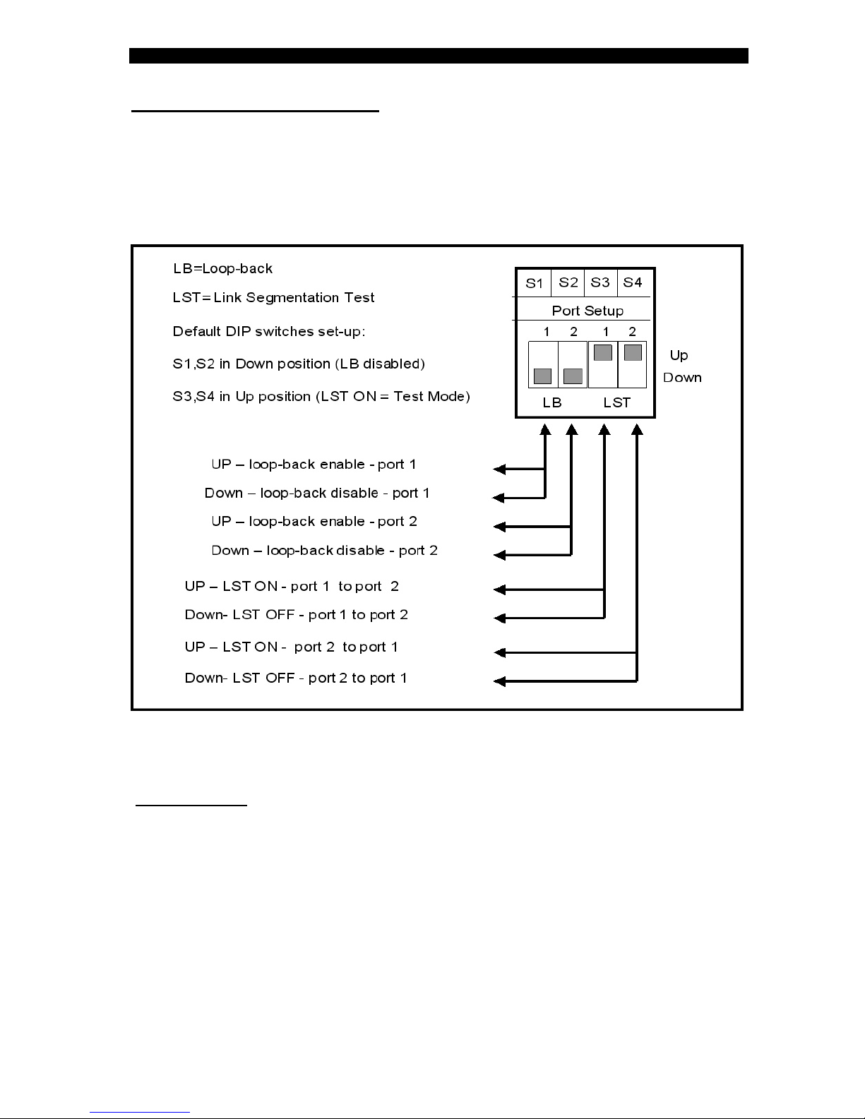
8 – DIP switches setting.
Each GSM1000 unit is equipped with an array of 4 DIP switches (front panel) that
facilitate the proper testing and setting of the F/O ports for optimal operation.
The following operations can be implemented on each F/O port:
•Loop-back enable / disable
•Link segmentation test: LST ON (Test mode)
•LST OFF (Link failure notification = Fault Propagation enabled)
Notes: Port 1: F/O port 1000Base-SX/LX (input port) - UNI
Port 2: F/O port 1000Base- LX (output port) - OA
LB (loop-back)
In normal operation, the LB DIP switches are in disable mode (DOWN position)
When it is necessary to perform a loop-back test in the selected port, then the
associated LB DIP switch should be enabled (UP position). The appropriate
LB LED will light to indicate that the selected GSM1000 port is in loop-back mode.
Local Loop-back operation: incoming received data on the RX port is looped back and
transmitted from the TX port.
Note: before applying Power to the unit, ensure that the LB DIP switches are in
DOWN position (LB disabled).
Note: When the GSM1000/MA CPE devices are present in the network (normally
connected to a MetroStar module: MCM1000T or MCM1000S) and the MA
management is active and operational, the MA LB/LST commands will override
the DIP switches setting.

GSM1000 Gigabit Converter
13
9 – LST (Link Segmentation Test)
The LST in the GSM1000 is used to notify one Network device upon a link failure in the
other Network device, or in the opposite direction (Fault Propagation).
The setting of the LST switches has absolutely no effect as long as no link failure is
detected. Thus, data is communicated normally.
The LST DIP switches have two positions per data link direction.
S3 controls LST signals from the F/O port 1(1000Base-SX/LX) to Fiber port 2
(1000Base-LX). (See Figure 1 below).
When S3 is in its down position (LST OFF), a link down at the Fiber port 1 switches off
the Fiber output port 2, thus, signaling the other device upon the failure.
When S3 is in its up position (LST ON), a link down at the Fiber port 1 generates an
idle signal that is transmitted at the fiber output port 2 which does not affect the other
attached device. (provided that the tested link is intact and functional)
S4 controls LST signals from the Fiber port 2 to Fiber TP port 1.
When S4 is in its down position (LST Off), a link down at the Fiber port 2 switches off
the Fiber output port 1, thus, signaling the attached device upon the failure. When S4 is
in its up position (LST ON), a link down at the Fiber port 2 generates an idle signal that
is transmitted at the F/O output port 1 which does not affect the attached device.
(provided that the link is intact and functional)
Default Operation Mode: LST ON (“TEST” mode)
Users that do not require real time alert (Fault Propagation) upon a failure from one
Network device to the other Network device, should set S3 and S4 switches of both
converters in their Up position (LST ON).
Users requiring real time alert (Fault Propagation) upon a failure may define/setup one
direction of alert, or both directions. This can be from Network Device B to Network
Device A or/and the other way.
LST Operation
Figure –1 depicts a typical installation when Fault Propagation (LST OFF) from
Network device B to Network Device A is selected.
Switch position: Device C – S3 Down, S4 Up; Device D – S4 Down, S3 Up
Figure-1 Using LST (Link failure notification)
When a link failure is detected between Network device B and device C, it turns off the
transmission of device C, thus, turning Off the Fiber link input of device D. This turns
off the transmission of device D, thus, turning Off the F/O link input of Network device
A. Same events will take place in case the link between Network device A and
GSM1000D has failed (provided that DIP switches S3 (GSM1000D) and S4
(GSM1000C) are in LST OFF mode.

GSM1000 Gigabit Converter
14
The user may verify the integrity of the link segments by switching LST ON (S3 Up) at
device C. An idle signal is transmitted to device D that turns ON the links
at devices D and A. (S4 Up at device D alone turns On the link at Network Device A)
The LST ON may be thus used to verify that the tested link segments are intact and
operative. Figure 2 depicts the LST ON functionality
Figure – 2 LST ON (Test Mode)
The Link alert (Fault Propagation) can be also selected for both directions
simultaneously. (in both devices D and C the S4, S3 DIP switches are set to down
position (LST OFF).
If the 1000Base-LX link fails, when the LST IS OFF, appropriate signals are transmitted
to both remote Network Devices A and B alerting them that a link failure
has occurred.
The LST operates in the same manner when GSM1000/MA devices are in the
network (connected to a Metrostar module). The only difference is that the LST
commands are from the remote management and override the DIP switches
setting.In GSM1000/MA, the LST FO port 1 to port 2 function is not allowed
under management and the DIP switches S3 and S4 in GSM1000 /MA are by
default preset to Test Mode (LST ON) to preserve the MA link Integrity (see
Figure-3.
In Figure-3 the LST command port 1 to port 2 at GSM1000/MA is not allowed
to avoid the case that the MA management will fail if the user has inadvertently
disconnected the F/O link between Network device B and GSM1000/MA (or the
same a link has failed). If the LST P1>P2 were active at GSM1000/MA, upon the
failure of the GSM1000/MA port 1 link, this event will cause the failure of the F/O
links at MCM1000S and Network Device A, thus the MA management is lost.
Figure-3 – LST with GSM1000/MA

GSM1000 Gigabit Converter
15
10 – MA Concepts and Functions (GSM1000/MA &GSM1010/MA)
The MA™ (Micro Agent) is an on-chip management system providing the monitoring and
management of remote access devices without the need of an expensive SNMP agent module.
The MA™ does not require an IP address
The chip is embedded in both the remote units, mostly referred to as a CPE, and in the access
concentrator device deployed in the access node. A unique secured in-band management
protocol allows the two devices communicating between themselves over the fiber link bi-
directionally, therefore both monitoring and management commands can be remotely
performed on the CPE. Control frames are not forwarded to data ports
Micro Agent Basic System Block Diagram
When MA™ enabled devices are deployed at both ends of the fiber link, they automatically
learn about each other’s presence and begin providing full remote management functions
within 20 to 30m.seconds from the moment the link has been established. However, if an MA™
enabled devices cannot complete such handshake within that time, it concludes that the
opposite end device is not MA™ enabled, subsequently it bypasses its special functions and
operates like a standard, straight forward access device. Therefore there are no interoperability
issues between network devices which have MA™ chips embedded in them and those that
have not.
The following management functions are available for the GSM1000/MA and through an
MA™ enabled and SNMP managed MetroStar:
•Device status: display the device ports basic status and configuration settings.
(Port 1 and 2: Link status (SX, LX), Signal Detect (SX, LX), LST mode, Loop back
status (LX, port 2) and upstream bandwidth.
(also shown are the device Temperature and Firmware revision level)
•Device Control: provides the user with options to set the channel’s description,
to invoke the LB/LST control, set upstream bandwidth, enable/disable channel,
and to restore the device’s defaults setting.
The GSM10x0/MA devices generate a " Remote Power Failure" signal upon power
failure. The attached GBE module will show in its Module status this condition
(Remote device Power "fail"). The term "Remote Power Failure" in this manual is
sometimes referred to "Dying gasp" or "Last gap" by the industry as well in the
product specifications.
Note: for a detailed description, please refer to the MMM-01 Management
Manual (version 1.6.2 and up))

GSM1000 Gigabit Converter
16
11 – SLE (Subscriber Link Emulation)
If the remote device is a FibroLAN MA™ device (GSM1000/MA or GSM1010/MA) and
the MetroStar system is managed, the most powerful SLE feature can be deployed,
further enhancing the network resilience.
Figure-3 SLE Operation
FibroLAN’s Subscriber Link Emulation virtually emulates the subscriber’s device or
network connected to the F/O (or TP) port of the remote device (GSM10x0/MA) onto
the F/O link of the Network device A. When activated (controllable via the
management system only) it senses the loss of the F/O link connected to the remote
MA device, notifies the MCM1000S/L and cuts off the F/O link between the MCM1000S
module port 1and the port of the Switch/Router which is alerted in real time of the
subscriber’s failure. All this is performed without disrupting the main F/O link, thus
ensuring on-going control of the remote device (CPE) via MA.
It should be noted that if the F/O link of port 1 of the MCM1000S/L module
(normally connected to a switch/router port) has failed, the SLE will cut-off the
F/O link between the GSM1000/MA and the Remote Network device B providing
in this manner an optimal bidirectional safe operation.
Thus SLE has in effect two modes of operation:
•Downstream SLE mode: link failure of the MCM1000S/L module F/O input port
(port 1) will cause the link disconnect of the input port of the Network device B.
•Upstream SLE mode: remote GS1000MA device link input port failure will
cause the link disconnect of the Network device A.
Note: When both SLE and LST are enabled, the SLE will override the LST
mechanism if the input port link (at the MCM1000S/L module or at the remote MA
device) has failed. On the other hand, if the F/O link is disrupted (main F/O link)
the LST will take over and execute the required actions.
During normal network operation, it is recommended to activate the SLE mechanism.
(Enable Downstream and Upstream m odes through the management).
Users requiring real time alert (Fault Propagation) upon a failure may define both
directions of alert (in GSM1000) and in one direction in GSM1000/MA.
Use and operate the LST (in TEST mode) in order to determine and locate a failed
Link segment.
GSM1000 Gigabit Converter
17
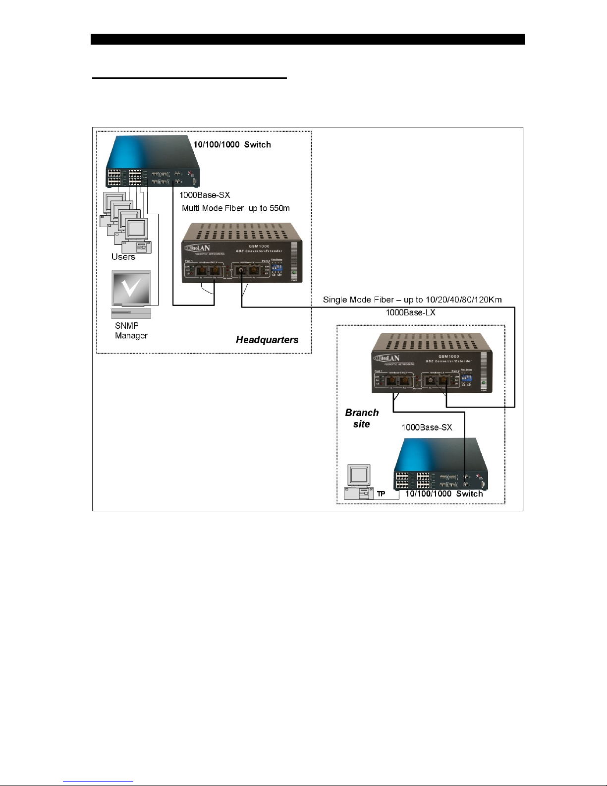
12 – Typical Configurations
Gigabit Multimode to Single Mode Configuration
The GSM1000 Media Converter extends the distance of your LAN by converting a gigabit
Multimode (or Single Mode) into a GBE Single Mode signal. The device provides conversion
from a MM (1000Base-SX) or SM (1000Base-LX) into a SM (1000Base-LX) link allowing
distance gain of up to 120Km transmission. A variety of models with various optical interfaces
are available to fit your requirements.
Use the 19” Rack shelf (CTF-RM P/N B012) for installation of up to 3 GSM units

GSM1000 Gigabit Converter
18
Network Extension Topology
If greater distances are needed, you may deploy and install the GSM1020
(instead of GSM1003) and GSM1018 (instead of GSM1007) extending your
network 120Km in each link.
See section 4 (product description for more details)

GSM1000 Gigabit Converter
19
Typical GSM1000/MA&GSM1010/MA Network
When the remote MA enabled devices are connected through their F/O link to a remote Access
Concentrator like the MetroStar which is MA™ enabled and SNMP managed, a
comprehensive set of monitoring and control functions can be implemented (through the
MCM1000S MA enabled module) into GSM1000/MA&GSM1010/MA remote devices.
The MMM-01 Management module installed in the MetroStar System will monitor,
control and manage the modules installed in the MetroStar chassis and the remote GSM/MA
devices. It will report alerts and traps to the SNMP Manager located in the Headquarters
building.
MetroStar™ equipped with a management module can be monitored and
managed from any SNMP management station running popular management
platforms (e.g. FibroLAN MetroView, HP OpenView, SNMPc, etc.)
13 – Default Parameters setting (GSM1000/MA)
Upstream bandwidth 1000Mbps
Channel enabled,
No port description
LB disabled
LST enabled (LST ON)
GSM1000 Gigabit Converter
20
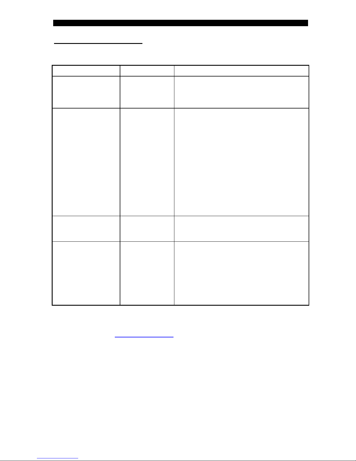
14 – Troubleshooting
Prior to performing the following procedures, verify that the LB DIP switches are in
DOWN position (loop-back disable), the LST DIP switches are in Test Mode (Up position)
Perform the same setup at the connected MetroStar module. Disable the SLE.
Problem Indication Corrective Action
No power Main power LED
PWR not lit
Check that the power supply cable is firmly connected
to the main power supply and rack mount power
source.
Check that the AC input power source is between 100
and 240VAC.
Fiber link not working
(port 1 or port 2)
Link LED not lit Verify that the correct fiber optic cables are being
used, i.e. multi-mode or single mode. Check that the
receive fiber is properly connected to the transmit port
of the remote fiber device AND the transmit port to
the receive port of the remote device.
The GSM1000/GSM1000/MA devices do not support
Auto-Negotiation in their F/O ports; thus any attached
device should be forced to A/N disabled (1000Mbps
and FDX).
Perform a loop-back test to verify link integrity
If LB test fails, verify that the output power of the fiber
optic port (s) is within manufacturer’s specifications.
Verify that the dB loss of the fiber cable you are
connecting to plus additional losses ( connectors
losses, normally 1,5dB per mated pair; Splice loss
0.3db max and 3db loss for safety margin) is within
the allowed dB budget
No transmit/receive on
F/O port
LED Act not lit Check the status of the various LEDs indications and
F/O Links.
Ensure that the equipment attached to the GSM is
properly configured and operating
MA is not working MA Active LED not
lit
Verify that the MCM1000S or MCM1000T module is
properly connected to the remote GSM1000/MA
device ( or GSM1010/MA )
Check that the Link LED is lit at both ends.
At the MetroStar management station perform the
following checks:
a. Link status b. Signal Detect status
c. Remote MA device status.
If necessary, you may perform the “ Restore link
default parameters “ command
If the problem persists after carrying out the above procedure, do the following: exchange
suspected GSM1000 with another similar GSM1000, and check connectivity and mode of
operation. If that has solved the problem, send your GSM1000 for repair. If the problem still
persists, there is probably some sort of general network failure. Call your local Fibrolan dealer or
•Date and place of purchase, from whom, original invoice
•The serial number and Firmware revision of the GSM1000 unit
•The serial number of the MetroStar™device and the type of the installed modules.
•The configuration of the equipment that is connected to the MetroStar™and the
sequence of events leading to the problem.
•Actions already taken and status files.
•Software revision levels of the installed equipment.
Table of contents


