FIC MB05W User manual

FIC MB05W Service Manual
FIC MB05 ServiceManual 1-1
MB05W
MB05W
(WB-B55)
1.1 Introduction
Thischapterprovidesthe outline features and operation of the MB05 including theBIOS
Setup program and other system options.
The MB05 notebookoffersthe latest in advanced portable computing and multimedia
technologythat even outperforms most desktop computers.It incorporates the latest Intel
Pentium - M processorand fullycompatibles with an entire libraryof PC software based on
operating systems suchas Windows2000 / XP. It also runs on future versionsof Windows. It
comes with a built-in keyboard, glide pad pointing device, soundsystem, PCMCIA slots, USB
(Universal SerialBus)port, IEEE 1394 port,advanced powermanagement and more new
multimedia features.
1.2 Feature Highlights
The MB05 includesavarietyof innovative features:
Category Specification Stepping
CPU Intel Pentium M Processor
: Banias 1.3/1.5 GHZ
Core Logic
Intel Montara-GM (North Bridge) :
CPU(Banias) I/F
VGAController
LVDS I/F
DVOB&DVOC IF.
RGBanalog I/F
200/266 DDR MEMORY I/F
Hub-Link I/F
Intel ICH4-M (South Bridge) :
Integrated Hub-Link I/F to connect with PCI
Bridge
Dual IDEMaster/Slave Controller,Integrated
DMA Controller
1.1/2.0 Universal Serial Bus HostController
Integrated 10/100M Fast Ethernet MAC
Controller
Integrated Audio Controllerwith AC97 V2.2
Interface
Advanced PowerManagement(ACPI)
RTC
Integrated PCI toLPC Bridge
Integrated Audio Controllerwith AC97 Interface
PCI Bus Interface (PCI 2.2 compliant)
GPIO
Advance PIC
PDF created with FinePrint pdfFactorytrial version http://www.fineprint.com

FIC MB05W Service Manual
1-2 FIC MB05Service Manual
Cache Memory L1 Cache (Pentium Processor internal):
64KB
8-waycache associativityprovides
L2 Cache (Pentium Processor internal):
1024KB Advanced Transfer Cache,8 way
associativity
8-wayset associative,32-byte line size,1 line per
sector
System Memory
Expansion Memory:2 SO-DIMMSlot (1.25”)
Size: 128/256/512MB/1G
Type: DDR DRAM, 3.3V
Data Path: 64Bit
Frequency: 266MHz
Please refer to the MB05 Keycomponent list in detail.
BIOSROM Flash ROM
1st Vendor : SST 49LF040A PLCC Package 4Mbit LPC
flash ROM
Super I/O SMSC LPC47N267
FDC, IEEE1284 PrinterPort
Serial Port x 1 ports
IR Port ASKIR, SIR, FIR, HPSIR, Consumer IR
Plug andPlaySupport
RTC + NVRAM Integrated in South Bridge (Intel ICH4-M)
Real Time Clockwith 256 byte extended
CMOS.
K/B Controller Mitsubishi M38859 LPC KBC
Internal K/B,Touch Pad, External K/Bor M/S
Supported A20Gate,firmware version 2.14
PMU NewPMU08
Mitsubishi M38859FFHP
EmbeddedController
TBD
VGA Controller Embedded in Intel Montara-GM
High Performance and high quality3D
accelerator
Integrated dual DVO bridge
Integrated LVDS Interface
Integrated RGB analog Interface
High performance 2D accelerator
Complete TV-OUT/Digital Flat Panel Solution
VRAM Share systemmemory, UMA (using DVMT configuration)
8/16/32 MB
TV out encoder None
CardBus
Controller RICOH R5C554 (PCI Card Buscontroller)
PC/Card Bus Type II x1
Build in smart card (none)
Sound
AC’97 CODEC
RealtekALC202
AC’97 Revision 2.2 Compliant
PDF created with FinePrint pdfFactorytrial version http://www.fineprint.com

FIC MB05W Service Manual
FIC MB05 ServiceManual 1-3
Modem MDC modem support
V.90, K56flex, ITU-T V.34, V.32, RJ11 Jack
TIA/EIA602, V.42
ITU-T V.17, V.29, V.27ter, V.21 Ch2
TIA/EIA578 Class1 FAX
Wake up on Ring
On board LAN Realtek8100BL
Support LAN boot( no used)
Support for auto-negotiation (10BASE-T and 100BASE-
TX)
Wake up On LAN( S1~S5)
3com Combo
802.11b
802.11 a+b Support by Intel Calexico Mini-PCI WirelessLAN Card
<Design ReadyOnly>
1394 RICOH R5C554 PCI-CARDBUS / 1394 OHCI-LINK / 1394
PHY
USB
Intel ICH4-M Integrated in South Bridge Intel ICH4-M)
Three Independent UHCI USB1.1 Host Controllers and
One EHCI USB2.0 Host Controller, support up to six port.
LegacyKeyboard/Mouse support.
Supports onlyone Debug port at port 1(firstport), it is at
USB2.0 transfer rate..
IDE Interface
(Intel ICH4-M) Fast IDE:
--Integrated multithreaded I/O linkmastering with read
pipelined streaming
--Dual independent IDE channel each with 16 DWFIFO
--Native and compatibilitymode
--PIO mode 0,1,2,3,4,and multiword DMA mode 0,1,2
--Ultra DMA33/66/100
PrinterInterface
IEEE 1284-Compatible
SPP mode (PS2 bi-directional mode)
EPP mode (EPP 1.7 and EPP1.9 IEEE1284
Compliant)
ECPmode (IEEE1284 Compliant)
Serial Interface None
External PS/2
Port
(M38859)
External Keyboard or PS/2 Mouse
Exclusivelyconnected.
Can use both device byusing branch
cable(option)
Universal Serial
Bus
(Intel ICH4-M)
--INTEL ICH4-M Integrated
--Three Independent OHCI USB1.1 Host Controllersand
One EHCI USB2.0 Host Controller, support up to six
port.
--Supportup to 6 USB ports
--Supportlegacydevices
--Overcurrent detection equipped
--Optional configured each port asa wake-up source
Infrared None
Modem 56K Data/FaxModem (v.90)
LAN 10/100 Base TX LAN
Lan boot support and WFM 2.0
LCD Panel 14.1”XGA
15 XGA
; Please refer to the MB05 Keycomponent list in detail.
PDF created with FinePrint pdfFactorytrial version http://www.fineprint.com

FIC MB05W Service Manual
1-4 FIC MB05Service Manual
HDD 2.5 inch HDD (Standard)
9.5mm Height
; Please refer to the MB05 Keycomponent list in detail.
CD-ROM
(Option) CD-ROM (9.5mm Height)
; Please refer to the MB05 Key component list in detail. .
FDD(None)
USB FDD
3 mode Support
; Please refer to the MB05 Keycomponent list in detail.
DVD
(Option)
DVD
9.5mm Height ,8X
; Please refer to the MB05 Keycomponent list in detail.
CD-RW,Combo 9.5mm Height ,24X
; Please refer to the MB05 Keycomponent list in detail.
Pointing Device Internal Touch Pad
PS/2 mouse I/F
Pad ALPS : KGDDET 005A
Please refer to the MB05T Keycomponent list in detail.
Keyboard Internal Keyboard
6.5mm Height, 3.0mm Stroke, 19mm Pitch
Please referto the MB05 Keycomponent list in detail.
Speakers
(audio) Two built-in dynamic speakers
40 x20mm,1W4
Microphone None
Buzzer Not support
Battery BatteryPack
Type: 8 cell Li-ION Battery with EEPROM
Voltage: 14.4V
Capacity: 4400mA(circle);3600mA(square)
Vendor: SANYO
Please refer to the MB05 Keycomponent list in detail.
RTC Battery Ni-MH Battery
Model: CR2032
Voltage: 2.9V
Capacity: 225mAh
Vendor: PANASONIC
DC/DC
Converter Daughter Board
5.0 V Max 6.0 A
3.3 V Max 6.0 A
12VMax120mA
2.5V Max 3.5A
1.8V Max3.5A
CPU Vcore 1.45V Max 22A
AC Adapter ADP75FB : Delta(Consign)
PA-1600-05F : Liteon
Input: AC100 240V, 50/60Hz
Output: 19V, 60W Peak80W(Liteon)
19V.75W(Delta)
Size: 115mm x50mmx29mm (Delta)
110mm x50mmx 29mm (Liteon)
Vendor: Delta or Liteon
Color : TBD
; Please refer to the MB05 Keycomponent list in detail.
Size W=308mm, D=268mm, H=27.7~31mm.
PDF created with FinePrint pdfFactorytrial version http://www.fineprint.com

FIC MB05W Service Manual
FIC MB05 ServiceManual 1-5
Weight Approx 4.9 lb = 2.2Kg
Battery Handling
Category Specification Remark
Power On Li-ion 3.5 h
BatteryCharging
Max Change
Current:
1.7A-1.75A±150mA
Power Off Li-ion 3.5 h
BatteryLife 1st Li-ion 4 h TBD
Save to RAM 1st Li-ion 1 Days TBD
Charge 24 hCMOS Battery
Discharge 5 year
System on
System off
Maximum 60WConsumption
power Typical 30W TBD
PDF created with FinePrint pdfFactorytrial version http://www.fineprint.com
FIC MB05W Service Manual
1-6 FIC MB05Service Manual
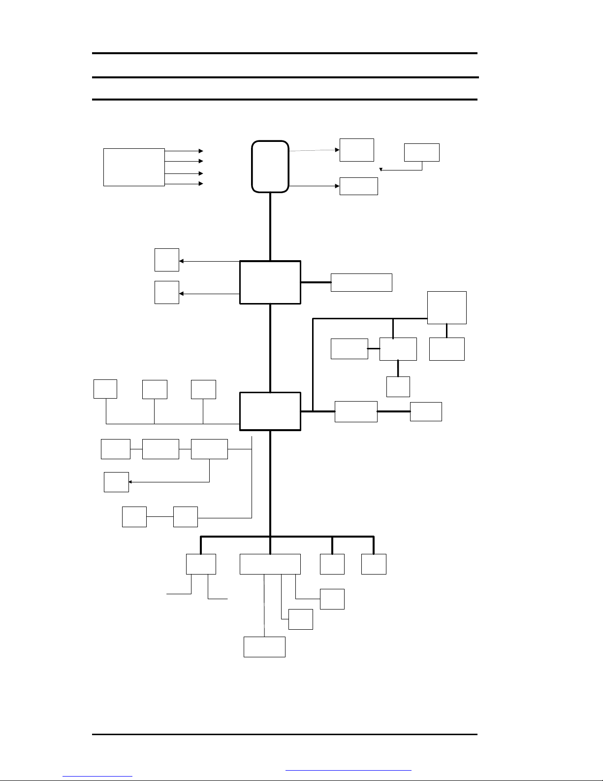
1.3 System Configuration
INTEL
Centrino
INTEL
ICH4-M
LPC47N267
INTEL
MONTARA-G
M
CPU
CORE
GMTG767
ICS950812
CPU PCI CLK
FIC ASIC
F010502-B0
CRT
LCD
USB1 USB0
USB2
DDRSDRAMX 2
MINI PCI
CONN
R5C554 PCMCIA
CNN X 2
G576
1394 PORT
RTL8100BL RJ 45
HD
PHONE ALC202GMTG1421
MDCRJ11
M38859 PMU08
COM
PORT
4M
ROM
PARALLEL
PS2
INT K/B GP
RGB
LVDS
32BIT PCI BUS
LPC
MBUS
MBUS
MIC
IN
Figure 1- 1 System Configuration Diagram
PDF created with FinePrint pdfFactorytrial version http://www.fineprint.com

FIC MB05W Service Manual
FIC MB05 ServiceManual 1-7
1.4 Quick Tour ofthe Notebook
Please take a moment to become familiar with the location and purpose of everycontrol, the
LED status panel, connectors and ports, which are illustrated in thissection. It is
recommended to first go through the UserGuide of the notebook, which isshipped together
with the notebookforinformation on how to operate its features.
1.4.1 The Inside of the Notebook
To open the LCD cover of the notebook, findthe coverlatch located at the front centerof the
LCD cover. Push the latch to the right to release and tilt the LCD cover up. Inside, you will see
the LCD displaypanel,keyboard, touch pad, status LED, and powerswitch.
Color LCD Display ❷
Status LED Indicator ❸
Keyboard
❹
Easy Buttons ❺
Power On/Resume
Button ❻
Touchpad Pointing
Device
Figure 1- 2 The Frontside of the Notebook
•Color LCD Display
The notebookcomputer comes with a colorLCD that you can adjust fora
comfortable viewing position. The LCD can be 15" TFT colorLVDS with
1024x768 XGA (Extended GraphicsArray) or1280x1024 SXGA+ resolution
panels. The features of the Color LCD Displayare summarized asfollows:
ŸTFT color LVDSwith 14.1" 1024x768 XGA or14.1" 1280x1024
SXGA+ resolution panels.
ŸCapable of displaying 16M colors(32-bit truecolor)on either size
panels.
ŸLCD displaycontrol hot-keysallows you to adjust the brightness of
the LCD.
ŸSimultaneous displaycapabilityfor LCD and external desktop
computer monitor.
PDF created with FinePrint pdfFactorytrial version http://www.fineprint.com

FIC MB05W Service Manual
1-8 FIC MB05Service Manual
•EasyButtons
There are threeeasybuttons used for activating wirelessfunction and
accessing user-defined functionsinstantlyand easily. Description of the easy
buttonsappearsin the latter part of thissection.
•Status LED Indicator
Keeps you informed of yournotebookcomputer’scurrent power statusand
operating status. Description of the statusicons appears in the latter part of
thissection.
•Power On/Resume Button
Switches the computerpower on and off, orresumeswhenever it isin
Suspend mode.
•Keyboard
ŸStandard QWERTY-keylayout and full-sized 82/84 keys keyboard
with Windowssystemhot-keys, embedded numerickeypad, 7 hot
keys, inverted "T" cursor arrow keys, and separate page screen
control keys.
ŸWide extra space belowthe keyboard panel for yourwrist or palm to
sit-on comfortablyduring typing.
•Touchpad Pointing Device
Microsoft and IBM PS/2mouse compatiblewith three selectbuttonsas one
Scroll button andtwo Touchpad clickbuttons. These three buttons array
below the Glidepad. Themiddle one is located with the Scroll button that lets
you execute the scroll page function. The two clickbuttonslocated at each
side support tapping selection and dragging functions. These buttons work
like a standard computer mouse. Simply moveyour fingertip over the Glide
Pad to control the position of the cursor.Use the selection buttonsbelowthe
Glide Pad to select menu items.
PDF created with FinePrint pdfFactorytrial version http://www.fineprint.com

FIC MB05W Service Manual
FIC MB05 ServiceManual 1-9
Easy Buttons
Œ
Wireless LANButton
•
Easy Button 1
Easy Button 2
Figure 1- 3 Easy Button
•WirelessLAN Button
Push this button to activate or inactivatethe Wireless LAN. When you
activate the wirelessLAN function, it will search the wirelessLAN signal
automaticallyif you had installed the driver
•EasyButton 1
You can define the specificfunction byyourself to active the program. For
example, you can define it to access the outlook98/2000/2002... utilityjust by
pressing this button. You can simplifyseveral procedures in entering into
Outlook98/2000/2002... environment. Formore understanding and
interesting, you can refer Section 2.5to recognize thedriverinstallation
proceduresin activating EasyButton 1.
•EasyButton 2
You can define the specificfunction byyourself to active the program. For
example, you can define it forproviding a veryconvenient wayin connecting
Internet onlybypressing thisbutton. For more understanding and interesting,
you can refer Section 2.5 to recognize thedriverinstallation proceduresin
activating EasyButton 2.
PDF created with FinePrint pdfFactorytrial version http://www.fineprint.com
FIC MB05W Service Manual
1-10 FIC MB05Service Manual
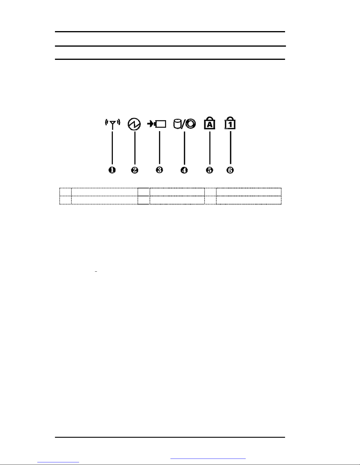
Status LED Indicator
Located just in front of the palmrest assembly,you will find three LEDsfor the powerand
batterycharge status.These LEDsare positioned to be visible even if the LCD cover is
closed.
Œ
Wireless LANStatus •
Power Indicator Ž
Batterycharging LED
•
HDD/CD Access •
Caps Lock ‘
Num Lock
Figure 1- 4 Status LEDIndicator
•Power Indicator
Lets you know that power to the systemisturned on. ThisLED ispositioned
so that you can see the power state whether the LCDpanel is opened or
closed.
ŸLightsgreen when the system is powered on
ŸLightsgreen blinking when the system isin Suspend to RAM.
•BatteryCharging LED
Lightsto indicatebatteryin charging status.
ŸLightsgreen to indicate that the batteryisin charging.
ŸLightsoff toindicatethe batteryisfullychargedorno batteryinstalled.
•HDD/CD Access
When LED in green light indicates that the system isaccessing either the
Hard Diskor opticaldiskdrive.
•CapsLock
When LED in green light indicates that the Caps Lockkeyon the keyboard is
activated. When activated, all alphabet keystyped in will bein uppercase or
capital letters.
•Num Lock
When LED in yellow light indicates that the Num Lockkeyon the keyboard is
activated. When activated, the embedded numeric keypad will be enabled.
PDF created with FinePrint pdfFactorytrial version http://www.fineprint.com

FIC MB05W Service Manual
FIC MB05 ServiceManual 1-11
•WirelessLAN Status
When LED in green light indicates that the system isaccessing data from or
isretrieving data bywirelessLAN.
1.4.2 Front Side ofthe Notebook
Cover Switch ❷Battery
Figure 1- 5 Front Side ofthe Notebook
•CoverSwitch
The cover (LCD panel)is locked when it isclosed. Slide the button rightaside
to release the latch foropening the cover of the computer.
•Battery
The batterypackis inserted here.
1.4.3 The RearSide ofthe Notebook
The right side of the notebookcomputeroffers the features shown in the followingfigure.
PS/2 Port ❷
Print Port ❸
COM Port
❹
VGA Port ❺
ModemPort ❻
DC-In Port
❼
Air-OutletVent ❽
Locking Device Keyhole
Figure 1- 6 RearSide of the Notebook
•PS/2 Port
Lets you connect an external PS/2-style mouse, PS/2-style keyboard,or
PS/2-style numerickeypad to the system. With an optional Y-cable adapter,
you also can connect anycombination on two of these devices
simultaneously.
PDF created with FinePrint pdfFactorytrial version http://www.fineprint.com

FIC MB05W Service Manual
1-12 FIC MB05Service Manual
•PrintPort
Use this port to connecta parallel printer orotherparallel device. The
parallel portsupportsEnhanced CapabilitiesPort (ECP)standard. The
standard provides you with a greater processing speedthan the conventional
parallel port. The port also supportsbi-directional protocols.
+The default setting for the parallel port on your notebook computer is
setto Enhanced Capabilities Port (ECP). Some older parallel devices
may notfunction with the ECP default setting. You may need to adjust
the setting to accommodate your parallel device by changing the BIOS
setting.
•COMPort
Lets you connect a 9-pin external serial device such asa PDA, mouse, or
otherserial devices.
•VGA Port
Lets you attach an external CRT monitor for widerdisplay.You can run the
LCD displayand the external CRT monitor simultaneouslyor switch it to CRT
onlyusing the displayhot-key.
•ModemPort
A 56Kinternal fax/data modemis installed. It keeps you connected to the
outside world through networks.
•DC-In Power Port
Lets you connect the AC poweradapter in supplying continuouspower to
your notebookand recharging the battery.
•Air-Outlet Vent
Emitsthe heat out of your computer and keeps it within operating
temperature.
•Locking Device Keyhole
Lets you attach a Kensington securitysystem or a compatible lockto secure
your notebookcomputer.
1.4.4 The LeftSide ofthe Notebook
The left side of your notebookcomputer provides the features shownin the following figure.
To see allthe ports located on the left side,you can open the cover first.
PDF created with FinePrint pdfFactorytrial version http://www.fineprint.com
FIC MB05W Service Manual
FIC MB05 ServiceManual 1-13
USB Port ❷
LANPort ❸PC Card Slot
❹IEEE 1394 ❺
Built-in Stereo Speakers
Figure 1- 7 Left Side ofthe Notebook
•LAN Port
An internal 10Base-T/100Base-TX LAN module connects yourcomputer to
othercomputers/networksthrough a local area network(LAN).
•USBPort
The Universal Serial Bus(USB) port allows you to connect up to 127 USB-
equipped peripheral devices(forexample, printers, scanners and soon)to
your notebookcomputer
•IEEE 1394
IEEE 1394 portisa high speed I/O port that can transferhigh levels of data in
real-time, such as externalhard disk, Digital Video Camera.
•PC Card Slot
ŸLets you connect various PC cards such as memorycard
ŸSupportsboth 3V,5V 32-bit CardBus and 16-bit PC cards.
•Built-in Stereo Speakers
Integrated leftand right mini stereo speakerslocated at the two sides of the
N/B for sound and audio output foryour multimedia presentations orlistening
pleasure.
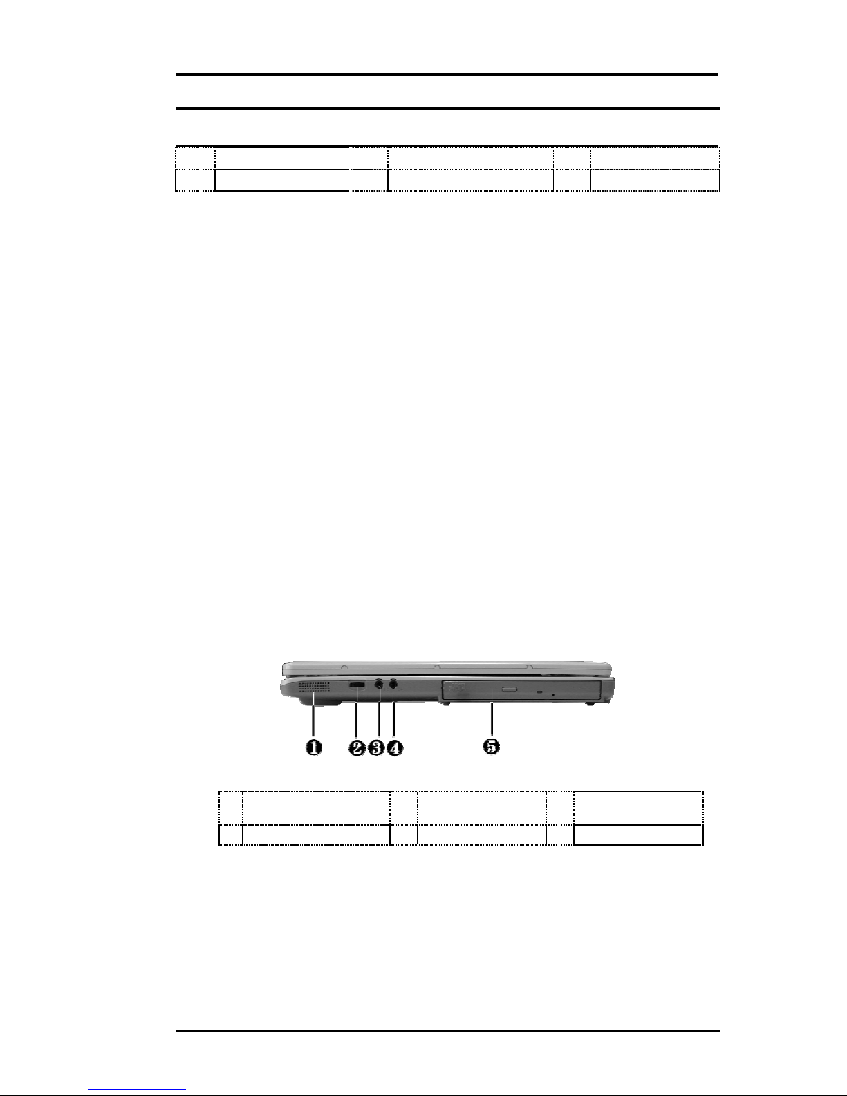
1.4.5 The Right Side ofthe Notebook
Built-in Stereo
Speakers ❷
Volume Control ❸
Microphone Jack
❹
Headphone Jack ❺
Optical Disk Drive
Figure 1- 8 Right Side ofthe Notebook
•Built-in Stereo Speakers
Integrated leftand right mini stereo speakerslocated at the two side of the
N/B for sound and audio output foryour multimedia presentations orlistening
pleasure.
•Volume Control
Allows you to control the speakervolume.
PDF created with FinePrint pdfFactorytrial version http://www.fineprint.com
FIC MB05W Service Manual
1-14 FIC MB05Service Manual
•Headphone Jack
Lets you plug in a stereo headphone, powered speakers, or earphone set
with 1/8 inchphono plug forpersonal listening.
•Microphone Jack
Allows you to connect an external microphone for monophonicsound
recording directlyinto your notebookcomputer.
•Optical DiskDrive
Allows you to load and startprograms from a compactdisc(CD) ora digital
video disc (DVD)and playconventional audio CDs. It also canmake CD by
using CD-R or CD-RW.
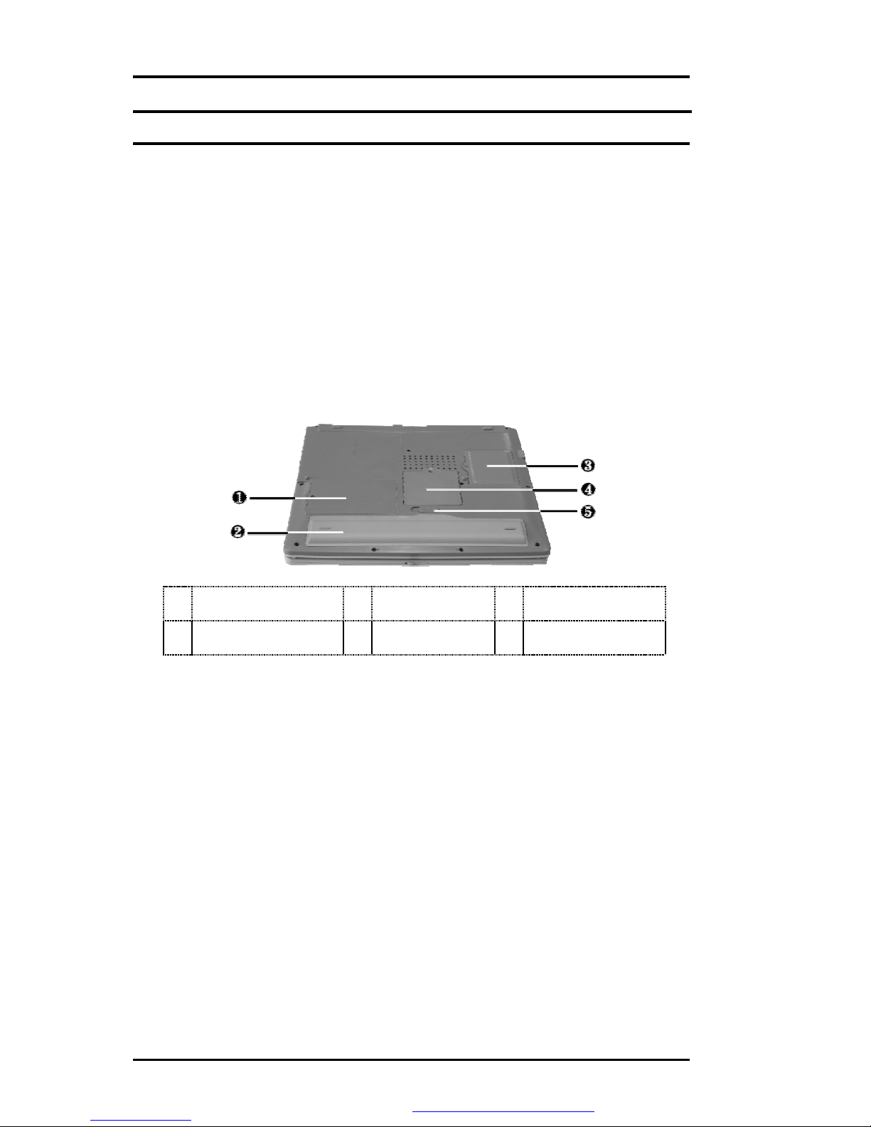
1.4.6 The Under Side ofthe Notebook
Hard Disk
Compartment ❷
Battery Bay ❸
Wireless LAN
Compartment
❹
Memory
Compartment ❺
Battery Release
Latch
Figure 1- 9 Under Side of the Notebook
•BatteryRelease Latch
Push the latch to the left end to remove the batterypack.
•BatteryBay
Equipped witha choice of Lithium-Ion (Li-Ion)batterypack.
•Hard DiskCompartment
Open this cover of thiscompartment to replace with other Hard DiskDrive.
Please refer to Chapter 7 for how to replace it.
•MemoryCompartment
Removethe screwto find two DIMM slots. One is inserted with DDR SDRAM
memoryboard configured bythe factory.The otheris emptyfor upgrade use.
•WirelessLAN Compartment
Provides optional wirelessLAN card inserted into thiscompartment for
executing relative functions.
PDF created with FinePrint pdfFactorytrial version http://www.fineprint.com

FIC MB05W Service Manual
FIC MB05 ServiceManual 1-15
1.5 Notebook Accessories and SystemOptions
It isalso important to understand the accessoriesthat come along with the notebookand the
options forfullyutilizing the capabilitiesof the computer. This section describesbrieflywhat
these accessoriesand optionsare.
1.5.1 ACAdapter and Power Cord
The AC Adapter supplies external power to yourcomputer and at the same time chargesthe
internal batterypack. The AC adapter has an auto-switching design that can connectto any
100VAC ~ 240VAC power outlets. Connect the adapter to the ACwall outlet using the power
cord. You just change the power cord if you are going to useyournotebookin other countries
with differentconnector outlets.When you connect the AC adapter, it charges the battery
whether or not the notebookcomputeris powered on. There isan LED on the AC adapter to
indicate if DC power isalreadyavailable.
1.5.2 BatteryPack
Asidefrom the AC adapter,yourcomputer can alsobe powered through the internalbattery
pack. The batterypackuses rechargeable Lithium-Ion (Li-Ion)batterycellsthat provide long
computing hourswhen fullycharged and power management enabled. You should always
leave the batteryinside yourcomputer even when using the AC adapter as it alsoacts asa
back-up power supplyin case power from the AC adapteris cut off. It isalso veryimportant to
have the batterypackalwayscharged to preventbatterycell degradation.
1.5.3 Internal Modem Module
The notebookallowsyou to insert a proprietaryinternal 56Kbps-modemcard to the notebook
found onthe underside of the notebook. The internal modem card supportsonlyfax and data
communication and is V.90-compliant. You connect the telephone lineto the RJ-11 jackfound
on the rear side of the notebook.
1.5.4 Internal Ethernet LANModule
Thisnotebookcomes with an optional 10Base-T/100Base-TX LAN module that supports data
transfer rates at 10Mbps and can be up to 100Mbps.
1.5.5 DVD-ROM Drive
Otherthan the internal CD-ROMdrive,the notebookalso provides optional factorybuilt-in
DVD-ROM drive. DVD-ROM drives are also backward compatible with CD-ROM, so you can
also use anyaudio CDs, video CDs,photo CDs,and CD-R. Using a software MPEG-2/DVD
program,the notebookcan playbackanycommercial DVD movie titles.
1.6 System BIOS SETUP Program
Yourcomputer islikelyto have been properlysetup and configured byyour dealerprior to
delivery.However,you may find it necessaryto use the computer’s BIOS (BasicInput-Output
System)Setup program to change systemconfiguration information, such as the current date
and time, or yourhard diskdrive type. The Setup program can be accessed when you power
on the system and pressing the <F2>function key.
The settings that you specifywithin the Setup program are recorded in a special area memory
called the CMOSRAM.Thismemoryis backed up bya batteryso that iswill not be erased
when you turnoff or reset the system. Whenever you turn on the computer, the system will
read the settingsstored in the CMOS RAMandcompare them to the equipmentcheck
conducted during the PowerOn Self Test (POST). Ifan erroroccurs, an error message willbe
PDF created with FinePrint pdfFactorytrial version http://www.fineprint.com

FIC MB05W Service Manual
1-16 FIC MB05Service Manual
displayed on the screen, and you will then be prompted to run the Setup Program.
Asthe POST (Power-On Self Test)executesduring the boot up process, the screen will
displaythe following message:
Press<F2> toEnter SETUP
Pressthe <F2> keyto run the BIOS Setup program. The BIOS Setup programisorganized
into five menus which you can select using the ßand àkeys. To move fromone option to
another, you use the up and down arrowkeys while using the <F5> and <F6>, or <+>and <->
keysto change the settings. On the right hand side of the screen are some brief help
descriptionsof each item you want to change.
On the BIOS Setup program, you will findthe following parts on the screen:
•ItemSpecificHelp
The right side of the screen. Thisarea describes each parameterand its
available settings.
•MenuBar
The top line of the screen.Each of the five selections displaysits own screen.
•Parameters
The left side of the screen. This area lists the parameters and their current
settings.
•KeyStatus Bar
The bottom part of the screen. These linesdisplaythe keys available to move
the cursor, select a particular function and soforth.
To exit the BIOS Setup program, simplypressthe <Esc> keyandselect from the Exit menu
whether you want to Save changesand exit; Discard Changesand exit.
PDF created with FinePrint pdfFactorytrial version http://www.fineprint.com

FIC MB05W Service Manual
FIC MB05 ServiceManual 1-17
1.6.1 Using theMainMenu Setup
Phoenix BIOS Setup Utility
Main Advanced Security Boot
Exit
Item Specific Help
System Time:
[12
:00 :00]
<Tab>, <Shift
-
Tab>,
System Date: [02/19/2003] or<Enter> selects
LAN MAC Address 00-40-CA-C3-9A-07 field.
Boot DisplayDevice: [Both]
4
Primary Master [30006MB]
Secondary Master Installed CD/DVD
System Memory: 640 KB
Extended Memory: 112640 KB
CPU Type: Intel Pentium-MProcessor
CPU Speed: 1300 MHz
BIOSVersion: A.1A-2973-0812
F1
Help áâ
Select Item -/+ ChangeValues F9 Setup Defaults
Esc
Exit ß-->
Select Menu Enter
Select 4Sub-Menu
F10
Saveand Exit
•SystemTime
Allows you to change the system time using the hour:minute:second format
of the computer.
Enter the current time forreach field and use the <Tab>, <Shift>+<Tab>, or
<Enter> keyto move from one field or backto another.
You can alsochange the system time from your operating system.
•SystemDate
Allows you to set the system date using the month/date/yearformat.
Enter the current time forreach field and use the <Tab>, <Shift>+<Tab>, or
<Enter> keyto move from one field or backto another.
You can alsochange the system time from your operating system.
•LAN MACAddress
Thisfield reportsthe MAC address of the LAN module on your notebook.
•BootDisplayDevice
Lets you select the displaydevice.
•PrimaryMaster
Thisfield displayvarious parameters forthe hard diskdrive. If type [Auto] is
selected, the systemautomaticallysetsthese parameters. If type [User] is
selected, Cylinders, Heads and Sectors and other value can be edited.
PDF created with FinePrint pdfFactorytrial version http://www.fineprint.com

FIC MB05W Service Manual
1-18 FIC MB05Service Manual
•SecondaryMaster
Thisfield isfor information onlyasthe BIOSautomaticallydetects the optical
drive.
•SystemMemory
Thisfield reportsthe amount of base (or conventional)memoryfound bythe
BIOS during Power-On Self-Test (POST).
•Extended Memory
Thisfield reportsthe amount of extended memoryfound bythe BIOS during
Power-On Self-Test (POST).
•CPU Type
Thisfield reportsthe CPU type information detected bythe BIOS during
Power-On Self-Test (POST).
•CPU Speed
Thisfield reportsthe CPU speed information detected bythe BIOSduring
Power-On Self-Test (POST).
•BIOS Version
Thisfield isfor information onlyasthe BIOSdisplays the BIOS version during
the Power-On Self-Test (POST).
1.6.2 InternalHDD Sub-Menu
Phoenix BIOSSetup Utility
Main Advanced Security Boot
Exit
PrimaryMaster: [30006MB] Item SpecificHelp
Type:
[Auto]
Select the drive type
LBAFormat corresponding to the
Total Sectors: [58605120] fixed diskinstalled
MaximumCapacity: 30006MB in your system.
If type USERis
Multi-Sector Transfers: [16 Sectors] selected, Cylinders,
LBA Mode Control: [Enabled] Heads & Sectorsare
32 Bit I/O: [Disabled] Edited directly.
Transfer Mode: [FPIO 4/DMA 2]
Ultra DMA Mode: [Mode5]
F1
Help áâ
SelectItem -/+ ChangeValues F9 Setup Defaults
Esc
Exit ß-->
SelectMenu Enter
Select 4Sub-Menu
F10
Save andExit
Use the Type field to selectthe drive type installed. You can select different drive types as
CD-ROM, User, Auto, or None bypressing <Space>bar. Set thisoption to Auto soyour
computer will automaticallydetect the drive type duringpoweron. Set thisoption to None
when your computeris not installed anydevices. Press <Esc> toreturn to the Main Menu.
PDF created with FinePrint pdfFactorytrial version http://www.fineprint.com

FIC MB05W Service Manual
FIC MB05 ServiceManual 1-19
1.6.3 Using the AdvancedCMOS Setup
Phoenix BIOSSetup Utility
Main Advanced Security Boot
Exit
Item SpecificHelp
NumLock [LockOn] Selects Power-on state
for NumLock
Embedded ShareMemory [16MB]
Quiet Boot [Enabled]
Screen Expansion [Disabled]
LegacyUSB Support [Enabled]
USB2.0 [Enabled]
PXE OPROM [Disabled]
Wake on LAN from S5: [Enabled]
4
I/O Device Configuration
F1
Help áâ
SelectItem -/+ ChangeValues F9
Setup Defaults
Esc
Exit ß-->
SelectMenu Enter Select 4Sub-Menu
F10
Saveand Exit
•Num-Lock
Lets you specifyEnabled orDisabled foractivating or inactivating Num-Lock
function when system is booting.
•Embedded Share Memory
Lets you specifythe sharing memorysize ofthe Video chip from DDR
SDRAM. The Default sharing sizeis 32MB. You should carefullyspecifythe
value,since while the set value istoo high, the memorysize of your software
application will be reduced.
•Quiet Boot
Lets you specifythe boot screen to Logo screen or POST screen bychoosing
Disabled orEnabled, respectively.
•Screen Expansion
Lets you choose full-size screen or reduced size screen forviewing the
displaymode.
•LegacyUSBSupport
Lets you specifyEnabled orDisabled foractivating or inactivating Legacy
USBDevice function when system is booting.
•USB2.0
Lets you specifyEnabled orDisabled foractivating or inactivating USB 2.0
Device function when system isbooting.
PDF created with FinePrint pdfFactorytrial version http://www.fineprint.com

FIC MB05W Service Manual
1-20 FIC MB05Service Manual
•PXE OPROM
Lets you specifyEnabled orDisabled foractivating or inactivating PXE
OPROM Device function when system is booting. Please set it to default
value
•Wake on LAN from S5
Lets you activate orinactivate the LAN function when system isbooting by
specifying Enabled or Disabled option. Wake on LAN is a function that you
can boot the system from LAN remotely.
•I/O Device Configuration
Lets you configure input/output device such as Serial Port, Parallel Port, and
Floppydiskcontroller.
I/O DeviceConfiguration Sub-Menu
PhoenixBIOSSetup Utility
Main Advanced Security Boot
Exit
I/O Device Configuration Item Specific Help
Serial port A: [Auto] Configure serial port A
using options:
Parallel port: [Auto]
Mode: [Bi-directional] [Disabled]
No configuration,
[Enabled]
User configuration,
[Auto]
BIOS or OS chooses
configuration,
(OS Controlled)
displayed when
controlled byOS
F1
Help áâ
SelectItem -/+ Change Values F9 Setup Defaults
Esc
Exit ß-->
SelectMenu Enter
Select 4Sub-Menu
F10
Saveand Exit
•Serial portA
You can select the Enabled, Disabled, orAuto option forenabled ordisabled
the port, or automaticallysensed byBIOS or OS.
•Parallel port
Allows you to select the Enabled, Disabled, orAuto option forenabledor
disabled thisport, or automaticallysensed byBIOS or OS.
•Mode
Allows you to select a parallel mode as Bi-directional, EPP or ECPwhen the
parallel portis configured. When you set the configured parallel port to
PDF created with FinePrint pdfFactorytrial version http://www.fineprint.com
This manual suits for next models
1
Table of contents
Other FIC Laptop manuals


Popular Laptop manuals by other brands


HP
HP EliteBook 725 G2 datasheet

Compaq
Compaq 12XL125 - Presario - K6-2 533 MHz Maintenance & service guide

Toshiba
Toshiba Satellite Pro S200 user manual

EUROCOM
EUROCOM 1800N Road Warrior user manual

HP
HP Spectre 13 x2 PC Pro Ultrabook Maintenance and service guide

Toshiba
Toshiba Satellite M305-S4820 Specifications


