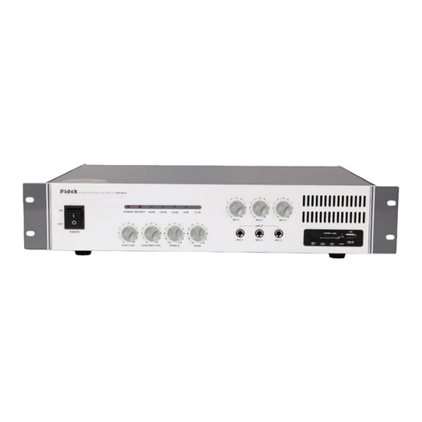
fidek FPT-8004 User manual

FPT-8004
FPT-15002
STA NDB Y
STA NDB Y
CH 1
CH 2
F P T- 15 0 0 2
SELE CT EN TER
--10dB10dB-10dB C LIP THER MAL FAULT
LOAD
SIGN AL --20 dB20dB-20dB
PARA L.
CH 3
CH 4
CH 1
CH 2
--10dB10dB-10dB C LIP THER MAL FAULT
PARA L.
SELE CT EN TER
F P T- 8 0 0 4
LOAD
SIGN AL --20 dB20dB-20dB
BRID GE
PARA L.
BRID GE
Professional Digital Power Amplifier
USER'S MANUAL
Pro fessi onal Dig ital Po wer Amp lifie r
Pro fessi onal Dig ital Po wer Amp lifie r

1
CONTENT
1. FEATURES.......................................................................................................................2
2. IMPORTANT SAFETY INSTRUCTIONS............................................................................3
3. FRONT PANEL FUNCTION INTRODUCTION
FPT-8004 FRONT PANEL..................................................................................................4
FPT-15002 FRONT PANEL................................................................................................ 5
4. REAR PANEL FUNCTION INTRODUCTION
FPT-8004 REAR PANEL....................................................................................................6
FPT-15002 REAR PANEL..................................................................................................7
5. SET...................................................................................................................................8
6. FUNCTION INTRODUCTION......................................................................................9-11
7. PC SOFTWARE ASSEMBING.....................................................................................12-13
8. DANTE CONTROL FUNCTION..................................................................................14-15
9. COMPUTER INTERFACE SOFTWARE COMMUNICATION CONTROL FUNCTION....................15
10. CONNECTION..............................................................................................................16
10. LINK DIAGRAM...........................................................................................................17
11. ONLINE CONTROL SYSTEMS......................................................................................18
12. TROUBLESHOOTING.................................................................................................. 18
13. SIGNAL FLOW DIAGRAM............................................................................................19
14. SPECIFICATIONS.........................................................................................................19

FEATURES
1. Plug and play USB/RJ45 network ports that are automatically connected.
2. Ethernet TCP/IP on-line muitiprocessor management.
3. DANTE network Audio Technology, low latency,not interference from conventional Analog signals. capable of up to
512 channels long distance digital,can be switched freely.
4. DSP high speed processing.
5. TFT color touch intuitive operation,level status display using intuitive.
6. Multiple input Y and output modes(Stereo、Sum、Input Y), Multiple input Y source selection(GENERATOR、
ANALOG、AES3、DANTE) with a variety of signal sources(white noise,pink noise,sine wave sweep signal).
7. Audio voltage limiter,delay control.
8. Input 6 segments of EQ including 2 types of multiple choice, output 8 segments of EQ have frequency, bandwidth,
gain settings.
9. Multiple filter type settings (Linkwitz-Riley、Butterworth、Bessel、6dB/oct、12Db/oct、18Db/oct、24dB/oct、
30dB/oct、36dB/oct、48dB/oct) .
10. With temperature, load detection fuction. Real-time detecting work temperature, voltage and current of power amplifier
automatically adjust output work rate that enables the amplifier to work in optimal working conditions.
11. 30 preset features for easy invocation.
12. Analyze the load of the power amplifier in real time, judge the negative sound box of the power amplifier, determine
whether there is an open channel or a short circuit in the speaker line, and the whole speaker audio curve can be scanned
prior to normal use after booting,make sure all systems of the speaker is good.
13. Multi-user program management is easy to operate.
2

1. Read these instructions.
2. Keep these instructions.
3. Heed all warnings.
4. Follow all instructions.
5. Do not use this apparatus near water.
6. Clean only with dry cloth.
7. Do not block any ventilation openings. Install in accordance with the manufacturer's instructions.
8. Do not install near any heat sources such as radiators, heat registers, stoves, or other apparatus (including amplifiers)
that produce heat.
9. Do not defeat the safety purpose of the polarized or grounding-type plug. A polarized plug has two blades with one
wider than the other. A grounding type plug has two blades and a third grounding prong. The wide blade or the third
prong are provided for your safety. If the provided plug does not fit into your outlet, consult an electrician for
replacement of the obsolete outlet.
Protect the power cord from being walked on or pinched particularly at plugs, convenience receptacles, and the 10.
point where they exit from the apparatus.
11. Only use attachments/accessories specified by the manufacturer.
12. Use only with the cart, stand, tripod, bracket, or table specified by the manufacturer, or sold with the apparatus.
When a cart is used, use caution when moving the cart/apparatus combination to avoid injury from tip-over.
13. Unplug this apparatus during lightning storms or when unused for long periods of time.
14. Refer all servicing to qualified service personnel. Servicing is required when the apparatus has been damaged in
any way, such as power-supply cord or plug is damaged, liquid has been spilled or objects have fallen into the
apparatus, the apparatus has been exposed to rain or moisture, does not operate normally, or has been dropped.
The apparatus shall not be exposed to dripping or splashing and that no objects filled with liquids, such as vases, 15.
shall be placed on the apparatus.
16. The MAINS plug is used as the disconnect device, which shall remain readily operable.
IMPORTANT SAFETY INSTRUCTIONS
Disposal of Old Electrical & Electronic Equipment (Applicable in the European Union and
other European countries with separate collection systems)
The recycling of materials will help to conserve natural resources. For more detailed information about recycling of
this product, please contact your local Civic Office, your household waste disposal service or the shop where you
purchased the product.
This symbol on the product or on its packaging indicates that this product shall not be treated
as household waste. Instead it shall be handed over to the applicable collection point for the
recycling of electrical and electronic equipment. By ensuring this product is disposed of
correctly, you will help prevent potential negative consequences for the environment and
human health, which could otherwise be caused by inappropriate waste handling of this product.
3

STA ND BY
CH 3
CH 4
CH 1
CH 2
--10d B10 dB-10d B CLI P THE RMA L FAU LT
PARAL.
SEL ECT E NTE R
F P T- 8 0 0 4
LOA D
SIG NAL --2 0dB20d B-20dB
BRI DGE
PARAL.
BRI DGE
1 2
FPT-8004 FRONT PANEL
4
4
3
6
58
7 9 11
10
12
13
1
Pro fessi onal Di gital P ower Am plifi er
1. Vents
They are the main vents of amplifier,Please keep them clear to allow air flow.
2. Edit touch screem
The audio signal of network power amplifier can be balanced,divided,delay and limited by editing touch screen.
3. Opetional/Deterministic Code switch
Selection and determimation,left and right rotate select menu data,press lightly to determine.
4. Parallel indicator LED
Export CH1/CH2 from CH1 Input number, CH1/CH2 with CH1 messenge CH1/CH2 input from CH1/CH2.GUI soft
integrated indicator will light in these two condition.
5. Bridge indicator
When the output mode of GUI soft or touch screen control soft set to “bridge to single channel”, the bridge indicator
will light up.
6. Signal indicator LED
When there is signal input the signal LED will light.
7. Level indicator
When the input signal reaches -20dB ,the indicator of -20dB will light and if reach -10dB the indicator of -10dB will light.
8. Clipping indicator light
Input signal exceeds the max sinal value of input sensitivity will lead to the output signal distortion, pls reduce the input
signal to guarantee output signal not to be distortion.
9. Impedance indicator LED
When there is a problem with the load Impedance of the test amplifier connection, the indicator LED will light.
10. Temperature indicator LED
The Temperature indicator LED will light when the temperature of the amplifier is over high.
11. Protect indicator LED
When there is a problem with the amplifier the indicator LED will light.
12. Touch screen backlight control
If not touch the screen after 15 minutes the backlight will be crushed out, touch the switch to turn of the backlight and
touch again the screem the backlight will light.
13. USB Debug port
The user can use the USB line to connect the amplifier with the PC, also can use the GUI soft in PC to contral the amplifier.
FRONT PANEL FUNCTION INTRODUCTION

5
STA ND BY
1 2
CH 1
CH 2
F P T- 15 0 0 2
SEL ECT E NTE R
--10d B10 dB-10d B CLI P THE RMA L FAU LT
LOA D
SIG NAL --2 0dB20d B-20dB
PARAL.
3
4
5
6
7
8
9
10 11
12
1
FPT-15002 FRONT PANEL
Pro fessi onal Di gital P ower Am plifi er
1. Vents
They are the main vents of amplifier,Please keep them clear to allow air flow.
2. Edit touch screem
The audio signal of network power amplifier can be balanced,divided,delay and limited by editing touch screen.
3. Opetional/Deterministic Code switch
Selection and determimation,left and right rotate select menu data,press lightly to determine.
4. Parallel indicator LED
Export CH1/CH2 from CH1 Input number, CH1/CH2 with CH1 messenge CH1/CH2 input from CH1/CH2.GUI soft
integrated indicator will light in these two condition.
5. Signal indicator LED
When there is signal input the signal LED will light.
6. Level indicator
When the input signal reaches -20dB ,the indicator of -20dB will light and if reach -10dB the indicator of -10dB will light.
7. Clipping indicator light
Input signal exceeds the max sinal value of input sensitivity will lead to the output signal distortion, pls reduce the input
signal to guarantee output signal not to be distortion.
8. Impedance indicator LED
When there is a problem with the load Impedance of the test amplifier connection, the indicator LED will light.
9. Temperature indicator LED
The Temperature indicator LED will light when the temperature of the amplifier is over high.
10. Protect indicator LED
When there is a problem with the amplifier the indicator LED will light.
11. Touch screen backlight control
If not touch the screen after 15 minutes the backlight will be crushed out, touch the switch to turn of the backlight and
touch again the screem the backlight will light.
12. USB Debug port
The user can use the USB line to connect the amplifier with the PC, also can use the GUI soft in PC to contral the amplifier.
FRONT PANEL FUNCTION INTRODUCTION

FPT-8004 REAR PANEL
1700W
220V~50Hz
25A/250V~
SECONDARY ETHERNET
PRIMARY
CH1/ 2 OUT
ANALOG INPUTS DIGITAL INPUT AES3
CH 2 IN C H1 I N
CH1/ 2 IN
CH 3 INCH 4 IN
CH3/ 4 INCH3/ 4 OUT
FPT-8004
1 3 4 5 6 7
8 9 10
6
2 3
+
+
CH1/2-
-
CH1 /2 +
CH 1 /2-
OUT PUTS
CH1
CH2
CH3
CH4
Prof essio nal Dig ital Po wer Amp lifie r
RISK OF E LECTR IC SHOC K
CAU TION
DO NOT OP EN
TO REDU CE THE RI SK OF ELE CTRIC S HOCK;
DO NO T RE MOVE COV ER ( OR B AC K); N O
USER S ERV ICEA BLE PAR TS IN SIDE ;REFE R
SERVI CING TO Q UALIF IED PER SONN EL.
POWER
ON
OFF
1. Power Switch
Push the switch to the “on” position,the indicator light,it mean the amplifier is turned on.Push the switch to the “OFF”
position,the amplifier is turned off.
2. Breaker
When the amplifier is under protection mode, the protecting device of circuit-breaker will leap up. And after cleaning
the breakdown, please press the device down,then it can back to work.
3. Fan Vents
They are the main vents of the amplifier. please keep them clear to allow air flow.
4. SPEAKON output socket
The output speaker socket of channel 1/2/3/4, connect speaker + to PIN 1+, connect speaker -to PIN 1-.
5. PRIMARY/ETH main network Dante port
Primary/Eth support Dante connection
6. Secondary/ETH second network Dante port
Secondary/ETH can guarantee the continuity of operation
7. ETHERNET network debugging port
It can connect with computer to configure various parameters.
8. Power input socket
Can use the matched power cable to contact with this port.
9. Analog input interface
CH1/CH2/CH3/CH4 Analog signal are input from this port.
there are two input connection way: parallel or not parllel.
10. AES number input/output port
Support AES-EBU signal input and output,the post line connection as below:
Parellel input connection not Parallel input conection
signal source signal source
AES-EBU number signal source
REAR PANEL FUNCTION INTRODUCTION

1700W
220V~50Hz
25A/250V~
www.fidek .com .cn www.fidek .com .hk
First Audio M anufac turing( GuangZh ou) Ltd .
FPT--15002
170 0 WATTS
22 0V ~5 0H z
SECONDARY ETHERNET
PRIMARY
ANALOG INPUTS DIGITAL INPUT AES3
CH 2 IN
CH1/ 2 OUT CH 1/2 IN
CH 1 IN
1 2 3 34 5 6 7
8 9 10
7
OUT PUTS
CH1
CH2
FPT-15002 REAR PANEL
POWER
ON
OFF
Prof essio nal Dig ital Po wer Amp lifie r
+
+
CH1/2-
-
CH1 /2 +
CH 1 /2-
Parellel input connection not Parallel input conection
signal source signal source
AES-EBU number signal source
1. Power Switch
Push the switch to the “on” position,the indicator light,it mean the amplifier is turned on.Push the switch to the “OFF”
position,the amplifier is turned off.
2. Breaker
When the amplifier is under protection mode, the protecting device of circuit-breaker will leap up. And after cleaning
the breakdown, please press the device down,then it can back to work.
3. Fan Vents
They are the main vents of the amplifier. please keep them clear to allow air flow.
4. SPEAKON output socket
The output speaker socket of channel 1/2, connect speaker + to PIN 1+, connect speaker -to PIN 1-.
5. PRIMARY/ETH main network Dante port
Primary/Eth support Dante connection
6. Secondary/ETH second network Dante port
Secondary/ETH can guarantee the continuity of operation
7. ETHERNET network debugging port
It can connect with computer to configure various parameters.
8. Power input socket
Can use the matched power cable to contact with this port.
9. Analog input interface
CH1/CH2/CH3/CH4 Analog signal are input from this port.
there are two input connection way: parallel or not parllel.
10. AES number input/output port
Support AES-EBU signal input and output,the post line connection as below:
REAR PANEL FUNCTION INTRODUCTION

CH1
CH2
CH1
CH2
CH1
CH2
8
CH1
INPUT
CH1
INPUT
CH2
INPUT
CH2
INPUT
CH1
INPUT
CH1
INPUT
CH2
INPUT
CH2
INPUT
SET
FPT-15002 Double channels mode: Stereo/CH1+CH2/Y type input, single channel: Bridge-single channel mode, Ch1/
CH2 can combine to bridge mode, CH3/CH4 can combine to bridge mode.
FPT-15002 Double channels mode: Stereo/CH1+CH2/Y type input.
In stereo mode, both channels operate independently,
with their input attenuators controlling their respective
levels.signal at channels CH1's output,while signal
at CH2's input produces output at CH2's output.
Stereo mode CH1+CH2 mode
Y type mode Bridge mode
CH1+CH2 input means CH1 plus CH2 signal to amplifier
then output the plus signal.
The input signal of CH1 and CH2 in parallel mode,
CH1 and CH2 output the same signal.
This mode combines the full power capabilities of both
channels into a single speacker system.the amplifier internally
re-configures so that both channels operate as a unit. signals
at channel CH1's input produces at speaker +, signals at
channels CH2's input produces output at speaker-.

9
FUNCTION DESCRIPTION
一、Normal boot Process
A. Connect the power line, press the power switch, display
screen displays the trademark number.
B. Then the machine starts loading the data and the machine
displays the main interface when it is finished. Display
the current input and output volume and the status.
二、Main menu
1. Go to the main menu display screen after booting normally.
2. Select the output gain that needs to be adjusted, and adjust
the parameter by rotating knob.
3. Click on [+], [-] of the output gain of the target channel
on the screen to adjust the parameter.
4. Tap the other buttons on the main screen to jump to other
interfaces and features.
5. Volume parameter is as follows: Music volume; Mute,
-100dB~0dB, step distance 0.5dB.
三、Setting up Menus
1. Right click on the main screen, upper corner of the <Settings> key
switch to the settings menu.
2. Enter your password in the lock screen function and click <lock>
to lock screen operation. Re-enter your password and click <unlock>
to unlock it. Only the machine interface and the settings interface
can be operated when the screen is locked.
3. Select the specified segment of the IP address, rotate the knob to
adjust the IP address, adjust IP with the machine-linked computer
IP to the modification, click <ok> to complete the modification.
An IP address is used to connect a machine to a computer's network.
4. Click on the right language to switch between Chinese and English.
5. Click on <Return> to return to the next level of menu.
四、Program Storage Menu
1. Switch to the program storage interface by clicking the
<storage> key of the main screen.
2. Press the previous page, the next switch program save the
location interface, a total of 30 programs can be saved.
3. Select the program serial number you want to save and the
default program name preset1~preset30 appears on the
spin knob, and then click <save>.
4. You can save it online by desktop control software and
save it with your own name, but notice that the Chinese
character library is incomplete, so please avoid using
Chinese when naming.
五、Program Call Menu
1. Switch to the program call screen by clicking the <call> key of the
main screen.
2. Press the previous page and the next page toggles the program call
location interface.
3. Select the program serial number you want to call, and then click ok.
4. You can also make calls online through desktop control software.
Note: GUI can also be used to store、 call、 delete、 save to the computer、
import from the computer and other functions of these programs.
六、Debugging the interface menu
1. Click the <debug> key of the main screen to enter the
debugging interface.
2. In the debugging interface、there are input、 output mode、
input equalization、 frequency division network、 output
equalization、 delay、voltage limit、 voltage-temperature、
load and other function keys.
3. Click the button to enter the corresponding function sub-interface.
七、Output Menu
1. The output mode includes bi-channel、 bridge-mono、 and the
required set-point hits (Application) will take effect. Take Channel 1
and 2 as an example;
2. Dual Channel Mode: Channel 1 and Channel 2 both have output in
this mode.
3. Bridging-Mono: In this mode, channel 1 has output and channel 2
has no output.

FUNCTION DESCRIPTION
八、Input Menu
1. Input mode selection: including stereo, superposition and
type Y input. Take channels 1 and 2 as example:
Stereo mode: The output of channel 1 is controlled by Channel 1
input and the Channel 2 is controlled by Channel 2 input,
neither of which interferes with the other.
Superposition mode: Channel 1 output is controlled by Channel 1
input and Channel 2 input. Channel 2 output is controlled
by Channel 1 input and Channel 2 input.
Y input mode: Channel 1 output is controlled by Channel 1
input and Channel 2 output is controlled by Channel 1 input.
2. Input source election: including generator mode, analog
mode, digital AES3 mode, Dante mode.
Generator mode: Used to produce white noise, power noise,
sweep signal and so on inside the machine.
Analog mode: For analog signal input, either 0dB or -6dB
attenuation can be selected.
Digital AES3 mode: For digital input.
Dante mode: For Dante signal input.
Switch to the corresponding input source when using the
corresponding input signal, otherwise no output will be generated.
3. Parameter adjustment: it can adjust the gain of white noise
and powder noise, the gain and speed of sweep of sweep signal.
White noise: turn on/off, -100dB~0dB, step 0.5dB.
Powder noise: Turn on/off, -100dB~0dB, step 0.5dB.
Sweep signal: Turn on/off, -100dB~0dB, step 0.5dB.
The higher the teaching value, the faster the sweep signal
changes and the maximum change speed is at 8 .
九、Voltage、Temperature、Current Detection Menu
1. Click on corresponding button in the debugging interface to enter
the temperature and voltage, current detection setting up the interface.
2. Temperature detection function
Temperature detection is a kind of over-temperature protection function
of the equipment. When the temperature is more than 85 degrees,
the output signal will compress1/3 and the temperature is more than
100degrees, the output signal will be compressed shrink 3/4, the
temperature is greater than 110 degrees, no output; when the temperature
falls to the normal range, the output will return to normal.
3. Voltage detection function
The voltage detection parameter information is as follows:
Actual voltage value (VAC):
Display the actual detected voltage value.
Voltage upper limit (VAC):
Manually set voltage limit values, 0 to 277V, and must be less than
the upper limit of the voltage. When the actual voltage detection
value is higher than the set voltage upper limit or lower voltage limit,
the device will enter the protective status, and the device will not
output until the detected voltage is restored to the normal range of output.
4. Current Detection Function
For the sane type of temperature detection when the detected output
current is greater than the machine can bear, it is forced to enter the
protective status, turn off all output and restore after restarting.
Remarks: The above voltage current temperature detection can be turn
on or off by switch control, and the protective function will not work
when it is in the off status.
十Enter the balance、
Parameters are as follows:
Input Equalization: Paragraph 6
Type: Parameter /Low frame/Viaduct
Frequency: 19.7Hz~20200Hz
Gain: -15dB~+15dB, step 0.5dB
Bandwidth: 0.011~3.595
十一、Crossover Network
Parameters are as follows:
High-pass filter/low-pass filter
Slope: 12dB/24dB/36dB/48dB
Type: Bessel/Butterworth/ Linkwitz-Riley
Gain: -15dB~+15dB, step 0.5dB
Bandwidth: 0.011~3.595
Polarity: +/-
10

11
十二 The output equalization、
Parameters are as follows:
Output equalization: 8 Paragraph
Type: Parameter
Frequency: 19.7Hz~20200Hz
Gain: -15dB~+15dB, step instance 0.5dB
Bandwidth: 0.011~3.595
十三 Delay setting、
1. Click the delay button in the debug interface to enter the delay
setting interface.
2. Corresponding to each channel delay, the delay range is 0~1s, step 0.021s.
3. Select the delay which needs to be modified, and rotate the encoder
to adjust.
4. Press the code will change the adjusting speed (steep), and the adjusting
speed can be divided into x1, x10 and x100. In third gear, step is 2.1s.
5. Click the close button below after the modification, if it is on, it means
the current channel delay has taken effect.
6. The delay is displayed in three units (milliseconds, feet, meters).
Adjust one of these values, and the others will be modified accordingly.
十四 Pressure limit settings、
1. Set the output voltage limit, which is divided into four
levels: close, -3dB,-6dB,-12dB.
2. Click on the selection to take effect, in the closed state
there is no pressure limit.
The corresponding gain is compressed under -3dB,-6dB,
and -12dB respectively.
十五 Load Detection Menu、
1. In the debug interface click the load button, you can enter the load
detection settings interface. 2、Load detection function is used to
test the working state of the sound in each frequency band.
3. Click on <open>, a sinusoidal signal output with a frequency varying
gradually from 19.7Hz to 20.2KHz is generated, Then check the feedback
of each band to determine the sound working status. Load curves can
be drawn and recorded through GUI operations.
十六 Panel locking function、
Panel lock function: According to the operation input password
in the 1.3 setting menu, or through the GUI online click panel lock
function enter password lock function to lock. The purpose of panel
locking is to prevent parameter misadjustment and to restrict other
users from changing device parameters and functions in case of
misoperation or interference.
十七、Processor manual reset function
1. Reboot and hold the encoder while waiting for the display to appear.
2. Press the encoder to reset the machine when prompted, the display
screen will appear when reset the work “Reset OK” prompt.
十八、Standby function
十九、Automatic Standby
1. The machine has no touch screen operation for 3 minutes , and without input, the LCD display screen will go out and the machine
will go into power-saving state.
2. The input signal or light touch on the LCD screen will wake up.
二十、Push-button standby
1. Press the standby button and the machine goes into standby mode. Standby mode forces the current output to go into a low-power
state and the LCD display to go out.
2. Press standby again to wake up and restore the output.
3. The key standby can be wakened by the key again.
FUNCTION DESCRIPTION

12
PC SOFTWARE INSTALLATION
4. User can choose USB to be connected, Please confirm the PC already connected with the equipment.
5. User can also choose website mode to connect,the procedure is as below:
1) Set the IP address in te menu.
2) Click the GUI menu to connect then choose TCPIP as below:
1. Insert a disc in the drive,open the PC to choose Setup.exe to installate.
2. Choose the right language.
3. Click next step to continue the installation.
The software will tell you the informaiton of the installation procedure,please according the tips to finish the installation.

0Device 192.168.0.199
13
PC SOFTWARE INSTALLATION
5. The main menu of the software.
Four channel two channel
3) Click scan( if use USB way to connect no need this step),it will show the IP if connect success.
4) Click the selection to choose the right equipment,then click connection.
0Device 192.168.0.199
192.168.0.199 Device
Device

14
Dante CONTROL FUNCTION
4. Click <Setting>,choose WDM,click <start>.
5. Open the software of Dante Controler.
1. Change from the input source selection to Dante input,connect the web line.
2. Open the software of Dante Virtual Soundcard.
3. Register the Licensing.

电脑界面软件通讯控制功能
15
Dante CONTROL FUNCTION
As the below picture. means the channel selection. Channel 15,16 means the accept port of the Dante.
We can see the condition of the machine when click the Device View if connect success. We can also see Sign change to
green color in the Receive of Dante.
SOFTWARE COMMUNICATION CONTROL FUNCTION IN COMPUTER
1. Control all the functions by GUI software.The rear panel cannot be operated on line.
2. Communication including parameter setting and reading, the adjustment of the audio parameter, software control and so on.
3. Parameter setting and reading including: parameter setting ,level reading, function lock,engineering lock and so on.
4. Software control can read one current procedure, 30 users' data operation.
5. We can click the “help” in the software to check the instruction details.

较远的音频信号
可通 过交换 机可 多次 中转
16
STANDB Y
STANDB Y
STANDB Y
STANDB Y
STANDB Y
CONNECTION
Dante amplifier
Network switch
Passive array speakers
Dante number sound console
Network switch
PC control port
(can use PC to adjust or use
amplifier to adjust)
Dante amplifier Passive speakers
Passive speakers

17
ON-LINE CONTROL PROMPT
The users must read the following instructions carefully before making an online control operation. This increases the
risk of an exception such as offline, computer crash etc., when online control is performed:
1. To ensure that the machine is in the normal working range; please check that the AC power supply (AC) complies with
the machine allowed range before use.
2. If the conditions permit, the AC power outlet needs to have the grounding connection setting. And connect the grounded
power supply to the computer and machine
3. Don't install the same version and type of control program in the computer repeatedly.
4. Don't control all the controls in the computer in the appropriate file directly.
5. It should avoid on-line control operation in the environment of strong signal interference.
6. Don't plug in the machine after the machine is turned on, if any of the following actions may result in the failure of online
control or may even damage the machine or computer.
1) Before the implementation of the online, please do not move your computer, machine or online control cable after the
machine is turned on.
2) Don't move your computer, machine, or online control cable after the machine is successfully online.
3) Don't use machine panel after successful online operation, including touching the machine's any keystrokes.
4) Don't plug in a machine or personal computer connection after successful online connection.
5) Don't switch on the same type of online control software on your computer after you have successfully online.
6) Don't use a computer to control multiple machines after successful online.
7. Refer to the “Important Safety Matters” section of the machine <<Instructions for Use>>.
1. Computer that can implement on-line control 2. Computer interface to implement on-line control 3. Grounding of AC Power Supply
COMMON TROUBLESHOOTING GUIDELINES
Malfunction phenomenon Method of exclusion
No display on LCD screen, LED
lamp no display
Machine and computer interface
not USB
The machine and computer interface
are not online
Output channel no output
Liquid crystal display
“ERROR CELL ERROR”
Liquid crystal display
“exit by push encoder”
1. Check if the power cord is connected.
2. Whether the power switch is on.
3. Is the fuse broken.
4. Is the standby key pressed or in an automatic standby state.
1. Check that the line is connected properly
2. Check that the interface software matches the machine version
3. Close the interface software, reconnect the communication cable, and then
open the interface software online
1. Check that the network cable is connected properly
2. Check that the interface software matches the machine version
3. Check IP address is correct
4. Close the interface software, reconnect the communication cable, and then
turn on the interface software online
1. Make sure the input is normal
2. Make sure the output to the amplifier and loudspeaker line is normal
3. Check that the input mode selection is correct
4. Check if the function voltage, current and temperature protection is turned on,
which may lead to the protection state due to improper operation
5. Restart your machine
6. Multiple restarts are still not resolv3ed, please contact your reseller
1. Reset machine
2. Restart the machine
3. Multiple restarts are still not resolved, please contact your reseller
1. Reset machine
2. Restart the machine
3. Multiple restarts are still not resolved, please contact your reseller

FPT-8004 FPT-15002
18
900W X4
600W X4 1600W X2
300W X4 1000W X2
±0.5dB ±0.5dB
≥100dB ≥100dB
≥95dB≥98dB
≥70dB ≥70dB
20 kOhms,10 kOhms 20 kOhms,10 kOhms
220V~50/60Hz 220V~50/60Hz
483x354x88mm 483x354x88mm
Dante 4 Channel (2xRJ45) 2 Channel (2xRJ45)
SIGNAL FLOW GRAPH
Output
mode
selection
Output
Output
High-pass/
low-pass Filter
High-pass/
low-pass Filter
Force delay
processing
Force delay
processing
Voltage limit
processing
Voltage limit
processing Detection
processing
Detection
processing
Channel 1
Input
Channel 2
Input
Input mode
selection
Input mode
selection
SPECIFICATIONS
Model number
The above technical specifications are subject to change without notice.
Output Port Helices Helices
Digital
Analog
4Channel(12-pin phoenix plug)
4Channel(12-pin phoenix plug)
2Channel(6-pin phoenix plug)
2Channel(6-pin phoenix plug)
Input Port
Dimensions(WxDxH)
Power Supply Voltage(±10%)
Dissipate heat Automatic Speed Regulation Air Cooling Automatic Speed Regulation Air Cooling
Analog input impedance(balanced
input, nonequilibrium input
Channel Separation (1KHz)
Signal-to-noise ratio [SNR]
(analog signal input)
Signal-to-noise ratio [SNR]
(digital signal input)
Frequency response(8Ω, 20Hz-20KHz)
Max Output Power @8Ω
Max Output Power @4Ω
Max Output Power @2Ω

This manual suits for next models
1
Table of contents
Other fidek Amplifier manuals
Popular Amplifier manuals by other brands

Avenue
Avenue 6600 Installation, configuration and operation information

Soundstream
Soundstream LIL'WONDER LW1.1100D Owner's manual and installation guide

Ascent
Ascent ACT AT5200 Quick reference guide

Blackstar Amplification
Blackstar Amplification Sonnet 120 owner's manual

Audio Note
Audio Note KAGEKI BALANCED Owner's Information

Gryphon
Gryphon Antileon Signature owner's manual
