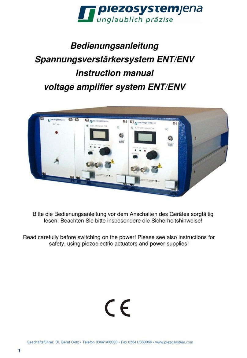
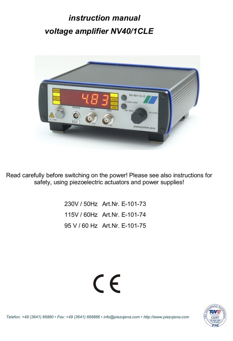
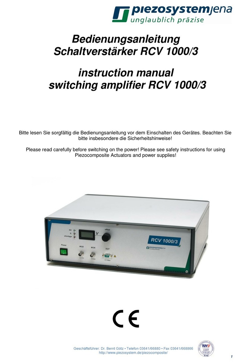
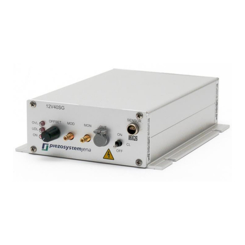
piezosystemjena nano box USB User manual

nano box USB
instruction manual
voltage amplifier
Read carefully before switching on the power! Please see also instructions for safety when
using piezoelectric actuators and power supplies!
Version: 2.0 last change: 2/23/2012 JF

Table of Contents
......................................................................................................................................11Introduction
......................................................................................................................................12Certification of piezosystem jena
......................................................................................................................................23Declaration of Conformity
......................................................................................................................................24Purchased Parts Package
......................................................................................................................................25Instructions for Using Piezoelectric Elements and Power Supplies
......................................................................................................................................36 Safety Instructions
......................................................................................................................................46.1 Installation, Power Supply
......................................................................................................................................46.2 Operation
......................................................................................................................................46.3 Maintenance and Inspection
......................................................................................................................................56.4 Environmental Conditions
......................................................................................................................................57 How to Operate the Voltage Amplifier
......................................................................................................................................57.1 Overview
......................................................................................................................................67.2 Technical Data
......................................................................................................................................77.3 Initiation
......................................................................................................................................7Installing the USB Driver (Windows XP)7.3.1 ......................................................................................................................................13Installing the USB Driver (Windows 7)7.3.2 ......................................................................................................................................197.4 Operation
......................................................................................................................................19Connecting the Power Supply7.4.1 ......................................................................................................................................19Connecting the Piezoelectric Actuator7.4.2 ......................................................................................................................................19Controlling via USB (VCP)7.4.3 ......................................................................................................................................198Drawings
......................................................................................................................................198.1 Output Connector for Actuator D-SUB15pin (male)
......................................................................................................................................198.2 USB Connector
......................................................................................................................................208.3 Power Supply Connector
......................................................................................................................................209Appendix
......................................................................................................................................209.1 Command Description
......................................................................................................................................21Command List9.1.1 ......................................................................................................................................22Command: idn9.1.1.1 ......................................................................................................................................22Command: rst9.1.1.2 ......................................................................................................................................22Command: break9.1.1.3 ......................................................................................................................................23Command: start9.1.1.4 ......................................................................................................................................23Command: stop9.1.1.5 ......................................................................................................................................24Command: stat9.1.1.6 ......................................................................................................................................24Command: err9.1.1.7 ......................................................................................................................................25Command: def9.1.1.8 ......................................................................................................................................25Command: defp9.1.1.9 ......................................................................................................................................26Command: hvon9.1.1.10 ......................................................................................................................................26Command: volt9.1.1.11 ......................................................................................................................................27Command: mvolt9.1.1.12 ......................................................................................................................................27Command: pos9.1.1.13 ......................................................................................................................................28Command: mpos9.1.1.14 ......................................................................................................................................28Command: sens9.1.1.15 ......................................................................................................................................28Command: cl9.1.1.16 ......................................................................................................................................29Command: ki9.1.1.17 ......................................................................................................................................29Command: resgen9.1.1.18

......................................................................................................................................30Command: version9.1.1.19 ......................................................................................................................................30Command: serno9.1.1.20 ......................................................................................................................................30Command: s9.1.1.21 ......................................................................................................................................31Table-Driven Generator9.1.1.22 ..............................................................................................................................31Command: tbres9.1.1.22.1 ..............................................................................................................................32Command: tbpos9.1.1.22.2 ..............................................................................................................................32Command: tblo9.1.1.22.3 ..............................................................................................................................33Command: tbhi9.1.1.22.4 ..............................................................................................................................33Command: tbptr9.1.1.22.5 ..............................................................................................................................34Command: tbval9.1.1.22.6 ......................................................................................................................................34Function Generators9.1.1.23 ..............................................................................................................................34Command: sin9.1.1.23.1 ..............................................................................................................................35Command: rect9.1.1.23.2 ..............................................................................................................................36Command: tria9.1.1.23.3 ......................................................................................................................................369.2 Status Double Word
......................................................................................................................................379.3 Error Double Word
......................................................................................................................................399.4 Default Double Word

Introduction1
1 Introduction
This manual describes the piezo amplifier nano box USB from piezosystem jena.You will also find additional
information regarding piezoelectric products.
If you have any problems please contact the manufacturer of the system:
piezosystem jena,Pruessingstrasse 27, 07745 Jena / Germany. phone: +49 36 41 66 88-0
2 Certification of piezosystem jena
The company piezosystem jena GmbH has been certified by DIN EN ISO 9001 since 1999.

Certification of piezosystem jena 2
This instruction manual includes important information for using piezo actuators. Please take time
and read this information. Piezo positioning systems are mechanical systems with highest precision.
Correct handling guarantees the precision over long time.
3 Declaration of Conformity
EU-Declaration of conformity
This certificate is issued for the following systems:
nano box USB
piezosystem jena GmbH
Pruessingstrasse 27
07745 Jena / Germany
The system as described above herewith complies with the requirements of the European
standards as follows:
EN 61010-1:2001
EN 61326-1:2006
EN 61326-1:2006
declaration issued by:
piezosystem jena GmbH
(General Manager)
Jena, Sept. 2011
4 Purchased Parts Package
Please check the completeness of the delivery after receiving the shipment:
·voltage amplifier nano box USB
·24V DC wide range power supply adapter
·USB cable
The instruction manual and the USB driver can be downloaded from our website www.piezojena.com under
Downloads & Publications.
5 Instructions for Using Piezoelectric Elements and Power Supplies
·The piezoelectric actuators from piezosystem jena are controlled by voltages up to 150V. These values
can be quite hazardously. Therefore read the installation instructions carefully and only authorized personal
should handle the power supply.
·After transportation, piezoelectric actuators should be allowed to adapt for approximately 2 hours to the
room temperature before being switched on.
·Piezoelectric actuators are made from ceramic materials with and without metallic casings. This materials
are relatively brittle. This should be noted when handling piezoelectric actuators. All piezoelectric elements
are sensitive to bending or shock forces.

Instructions for Using Piezoelectric Elements and Power Supplies3
·Due to the piezoelectric effect, piezoelectric actuators can generate electrical charges by changing the
mechanical load, by changing the temperature or by actions described above.
·The piezoelectric actuators are able to work under high compressive forces. Only actuators with a pre-load
can be used under tensile loads (these tensile forces must be less then the pre-load, given in the data
sheet). Please note that an acceleration of the ceramic material will occur (e.g. caused by fall down,
discharging or high dynamic application).
·If the actuator is driven by a voltage in the upper control range then the ceramic will move and generate an
opposite high voltage after disconnection.
·Aheating of the ceramic material will occur during dynamic operation. The heating is caused by
structure-dependent processes of loss. This may result in failures. The piezoelectric effect disappears if the
temperature exceeds the Curie temperature (usual values approx. 140°C - 250°C).
·The piezoelectric actuators work electrically as capacitors. The elements are able to store electrical energy
over a long period of time (up to some days). The stored energy may be dangerous. If an actuator remains
connected to the driving electronics then a shutdown will discharge the actuator within a second and
harmless voltage values will be reached quickly.
·The warming up or cooling down of a piezoelectric actuator can cause a longitudinal change which
generates voltages. The discharge potential should not be ignored due to the inner capacitance. This effect
is not significant at usual room temperature.
·The piezoelectric actuators from piezosystem jena are adjusted and glued. Any opening of the unit will
cause misalignment or possible malfunction and the guarantee will be lost.
·Please use only original parts from piezosystem jena.
·Please contact piezosystem jena or your local representative, if there are any problems with your actuator
or power supply.
Caution!
Shock forces may damage the built-in ceramic elements. Please avoid such forces, and handle the units
with care, otherwise the guarantee will be lost.
6 Safety Instructions
Icons
DANGER! This indicates a risk of electric shock. The associated warning should be observed.
CAUTION! This indicates additional information in the manual such as important operating and
maintenance instructions.
DANGER!
·Do not open the units! There are no user-serviceable parts inside. Opening or removing covers may expose
you to dangerous shock hazards or other risks. Refer all servicing to qualified service personnel.
·Avoid the ingress of liquids into the units! Electric shock, fire or equipment failure are possible.
·The OUT-connector of the front panel may drive hazardous voltages. Do not touch the contacts!
CAUTION!
·Allow adequate ventilation around the units. Do not block ventilated openings or place the units near a
radiator, oven or other heat sources.
·Work with the units only in a clean and dry environment! Only specially prepared units (e.g. actuators) can
work under other conditions!
·piezosystem jena does not give any warranty for damages or malfunction caused by additional parts not
supplied by piezosystem jena.Additional cables or connectors will change the calibration and other
specified data. This can change the specified properties of the units and cause them to malfunction.
·Piezoelectric elements are valuable, sensitive systems capable of the highest positioning accuracy. They will
demonstrate their excellent properties only if they are handled correctly! Please mount them properly only at
the special mounting points.
Safety Instructions 4
Immediately unplug your unit from the wall outlet and refer servicing to qualified service personnel under the
following conditions:
·The power supply cord or plug is damaged.
·The unit has been exposed to rain or water.
·Liquids ingressed into the unit.
·The unit does not work correctly when operated under the terms specified in this manual.
6.1 Installation, Power Supply
DANGER!
·Do not insert or unplug the power plug with wet hands, as this may result in electrical shock.
·Do not install in rooms, where inflammable substances are stored. If flammable substances come into
contact with electrical parts, this may result in fire or electrical shock.
·Do not damage or modify the power cord. Also, do not place heavy objects on the power cord, or pull on or
excessively bend it, as this could cause electrical damage and result in a fire or electrical shock.
·Always grasp the plug portion when unplugging the power plug. Pulling on the power cord may expose or
snap the core wire, or otherwise damage the power cord. If the cord is damaged, this could cause an
electricity leak and result in a fire or electrical shock.
CAUTION!
·Do not use accessories other than the provided (e.g. power cord). Plug the power cord only in grounding
equipment conductor power sockets.
·Avoid the power cord being a tripping hazard and select a place where the power cord could not be
damaged. Do not place any heavy objects on any cables.
·Do not block ventilated openings and allow adequate ventilation around the units' place.
·Plug the power cord completely in the grounding equipment conductor power sockets so that it can not
loosening inadvertently.
·Leave sufficient space around the power plug so that it can be unplugged easily. If objects are placed
around the power plug, you will be unable to unplug it in an emergency.
·The power plug is the cutoff point from the public power supply.
6.2 Operation
DANGER!
·Do not open the units! There are no user serviceable parts inside. Opening or removing covers may expose
you to dangerous shock hazards or other risks. Refer all servicing to qualified service personnel.
·Do not spill water or inflammable substances inside the voltage amplifier. If any of these substances comes
into contact with an electrical component of the voltage amplifier then it may result in a fire or electrical
shock.
CAUTION!
·If the voltage amplifier emits smoke, big heat or unusual smells, immediately turn off the voltage amplifier
and unplug the power plug from the outlet. Then contact our technical service.
6.3 Maintenance and Inspection
CAUTION!

Safety Instructions5
·Turn off the voltage amplifier and unplug the power plug before cleaning the exterior box of the voltage
amplifier. Failure to observe these items may result in a fire or electrical shock.
·The cleaning of the exterior box should be done by using a firmly wrung-out cloth. Do not use alcohols,
benzene, paint thinner or other inflammable substances. If flammable substances come into contact with an
electrical component of the voltage amplifier then fire or electrical shock are possible.
6.4 Environmental Conditions
The voltage amplifier can be operated under the following environmental conditions:
·indoor
·altitude up to 2000 m
·temperature: 5 ... 35 °C
·relative humidity: 5 ... 95% (non-condensing)
The recommended environmental conditions are:
·indoor
·altitude up to 2000 m
·temperature: 20 ... 22 °C
·relative humidity: 5 ... 80% (non-condensing)
7 How to Operate the Voltage Amplifier
7.1 Overview
The voltage amplifier nano box USB has been developed as an universal solution for single-channel
positioning tasks with low dynamics. An internal digital drift compensation controller allows the use of closed
loop actuators of the D-Series. Only strain gauge (SG) sensors are supported measurement systems.

How to Operate the Voltage Amplifier 6
view of the supply side
view of the actuator side
The communication between the nano box USB and the PC is realized via a virtual COM port (VCP). The VCP
allows the use of any terminal program (HyperTerminal, HTERM, ...).
The two-color LED for monitoring indicates the fault condition and the status of the nano box USB.The
different states are represented as follows:
LED Explanation
permanent RED There is no USB connection to the PC.
permanent GREEN OK.
flashing RED at short intervals Error, see Error Double Word.
flashing GREEN at short intervals The actuator is moving.
flashing GREEN at wide intervals The actuator recognition is in progress.
7.2 Technical Data
item number E-320-00
power supply 24V DC, +/-10%
max. current consumption 100mA
fuse 250mA, internal, self-resetting
dimensions [W x H x L] 24mm x 108mm x 68mm
weight 130g
number of channels 1
output power 1.5W

How to Operate the Voltage Amplifier7
output current 10mA
output voltage 0 ... 130V
output connector D-SUB 15
DAC resolution of the voltage output 16 Bit
ADC resolution of the measurement system 16 Bit
7.3 Initiation
When you open the package, please check to make sure that all the necessary parts are complete (see
packing list) and nothing is damaged.
Check the electronics and the actuator for any visible damage:
·The top and bottom plate of the actuator (if it does not have another shape) should be parallel each to each
other, without scratches.
·If there is any damage to the system please contact our local representative immediately!
·If the packaging material is damaged please confirm this with the shipping company.
Before you switch on the system, please check:
·The main voltage supplied in your country is the same as installed for the system (Check the voltage label
on the backside of the power supply adapter).
·Connect the power supply adapter.
·Connect the piezoelectric actuator by using the D-SUB15pin connector. Be sure the cables are connected
properly to the electronics.
The nano box USB is controlled exclusively via the USB interface. The nano box USB uses two power
supplies. The first is via USB for the control unit and the second is an external 24V DC wide range power
supply for the high voltage output.
Connect the nano box USB using the included USB cable to the PC. The LED for monitoring switches to
permanent red.
If the USB driver has been installed already on the PC then the nano box USB is recognized by the operating
system. The LED for monitoring flashes green at wide intervals for about 0.5 seconds and then switches to
permanent green.
Otherwise, the USB driver has to be installed on the PC. The USB driver supports Windows XP, Windows
Vista and Windows 7 in the 32-bit and 64-bit versions respectively. The USB driver installation procedure is
described below where the steps for Windows 7 are the same for Windows Vista.
7.3.1 Installing the USB Driver (Windows XP)
The USB driver for the nano box USB can be downloaded from the website www.piezojena.com under
Downloads & Publications. Copy the driver file at32uc3xxx_cdcx32_64.inf to a directory of your choice. In
the example below the directory is D:\.
Connect the nano box USB with the PC using the supplied USB cable.
Windows shows the detection of the new hardware in the notification area of the taskbar:
After a short time, Windows opens the Found New Hardware Wizard:

How to Operate the Voltage Amplifier 8
Select No, not this time and confirm with Next.
Select Install from a list or specific location (Advanced) and confirm with Next.

How to Operate the Voltage Amplifier9
Select Include this location in the search and enter the path of the directory of the driver files. Confirm with
Next.
The next window is blocked by a security warning dialog

How to Operate the Voltage Amplifier 10
that has to be confirmed with Continue Anyway.
Now, the installation of the driver continues by setting a system restore point.

How to Operate the Voltage Amplifier11
Confirm the completion of the installation with Finish.Windows shows the completion of the installation in the
notification area of the taskbar:
The name of the serial interface can be determined by opening the Device Manager as follows:
Open the context menu of the My Computer icon by clicking on it with the right mouse button. Select
Properties:
This will open the System Properties dialog:

How to Operate the Voltage Amplifier 12
In the Hardware tab, start the Device Manager.

How to Operate the Voltage Amplifier13
In the Device Manager, the new device appears under Ports (COM & LPT) as AT32UC3 CDC to UART USB
(COM3).
The port name COM3 is an example and may vary on a different PC. From now on, the nano box USB can be
operated with any terminal program.
7.3.2 Installing the USB Driver (Windows 7)
The USB driver for the nano box USB can be downloaded from the website www.piezojena.com under
Downloads & Publications.Copy the driver file at32uc3xxx_cdcx32_64.inf to a directory of your choice. In
the example below the directory is D:\.
Connect the nano box USB with the PC using the supplied USB cable.
The detection of the new device is show in the notification area of the taskbar:
The corresponding status information are as follows:

How to Operate the Voltage Amplifier 14
The installation fails because this is the first time the nano box USB is connected with the PC. The failure is
shown in the notification area of the taskbar:
Clicking the message shows the details:
You have to manually install the driver software. Open the Device Manager from the Windows Start Menu by
entering device manager in the search field:

How to Operate the Voltage Amplifier15
The unknown device appears under Other devices in the Device Manager:
Select the Unknown device. Open the Action menu and select Update Driver Software ....The following
dialog is started:

How to Operate the Voltage Amplifier 16
Select Browse my computer for driver software:

How to Operate the Voltage Amplifier17
Enter the path of the directory of the driver files into the field with the label Search for driver software in this
location.Confirm with Next.
The Windows Security warning has to be confirmed with Install this driver software anyway:
The installation continues by updating the driver software.
Table of contents
Other piezosystemjena Amplifier manuals

piezosystemjena
piezosystemjena NV40/3 User manual

piezosystemjena
piezosystemjena NV40/1CLE User manual

piezosystemjena
piezosystemjena NV100/D NET User manual

piezosystemjena
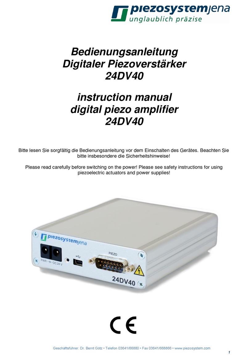
piezosystemjena 24DV40 User manual

piezosystemjena
piezosystemjena 30V300 User manual

piezosystemjena
piezosystemjena 12V40 Series User manual

piezosystemjena
piezosystemjena RCV 1000/3 User manual

piezosystemjena
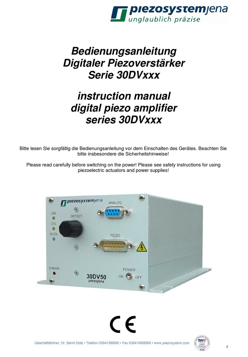
piezosystemjena series 30DV User manual

piezosystemjena
piezosystemjena NV200/D NET User manual

piezosystemjena
piezosystemjena ENT User manual