Fidelis Direct/Internal 10G User manual

www.fidelissecurity.com
QUICK START GUIDE
Fidelis Network™
Sensor Appliances
Rev-H
Fidelis Sensors
(Direct, Internal, Web, and Mail Appliances)
Based on HPE DL350-G9 and DL560-G9
Platforms
QUICK START GUIDE
Fidelis Network™ Sensor Appliances
www.fidelissecurity.com©Fidelis Cybersecurity
2
1. System Overview
Fidelis Sensors are the components that monitor the network environment for activities that may
indicate advanced threat, malware, and data theft. Fidelis Sensors analyze network traffic, deliver
alerts and session data to CommandPost, and deliver non-selective network session metadata to
Fidelis Collector for retrospective analysis.
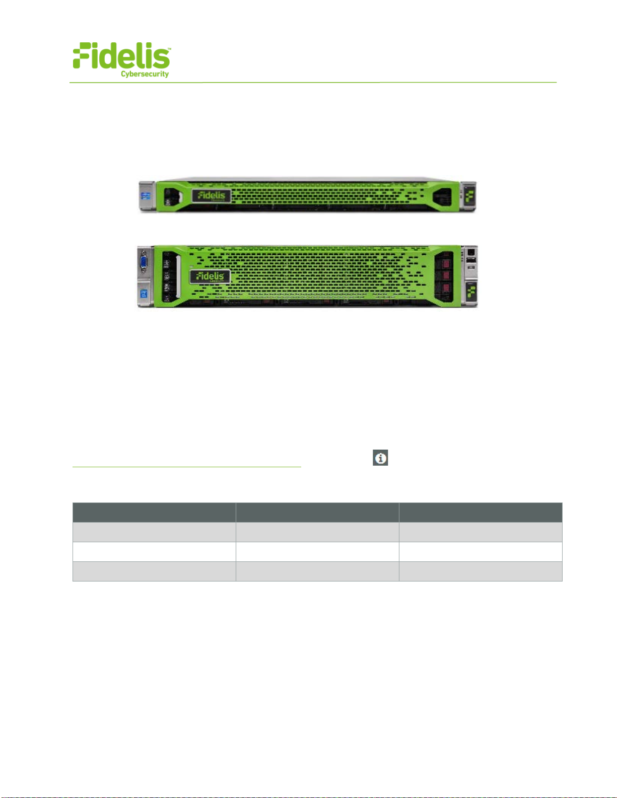
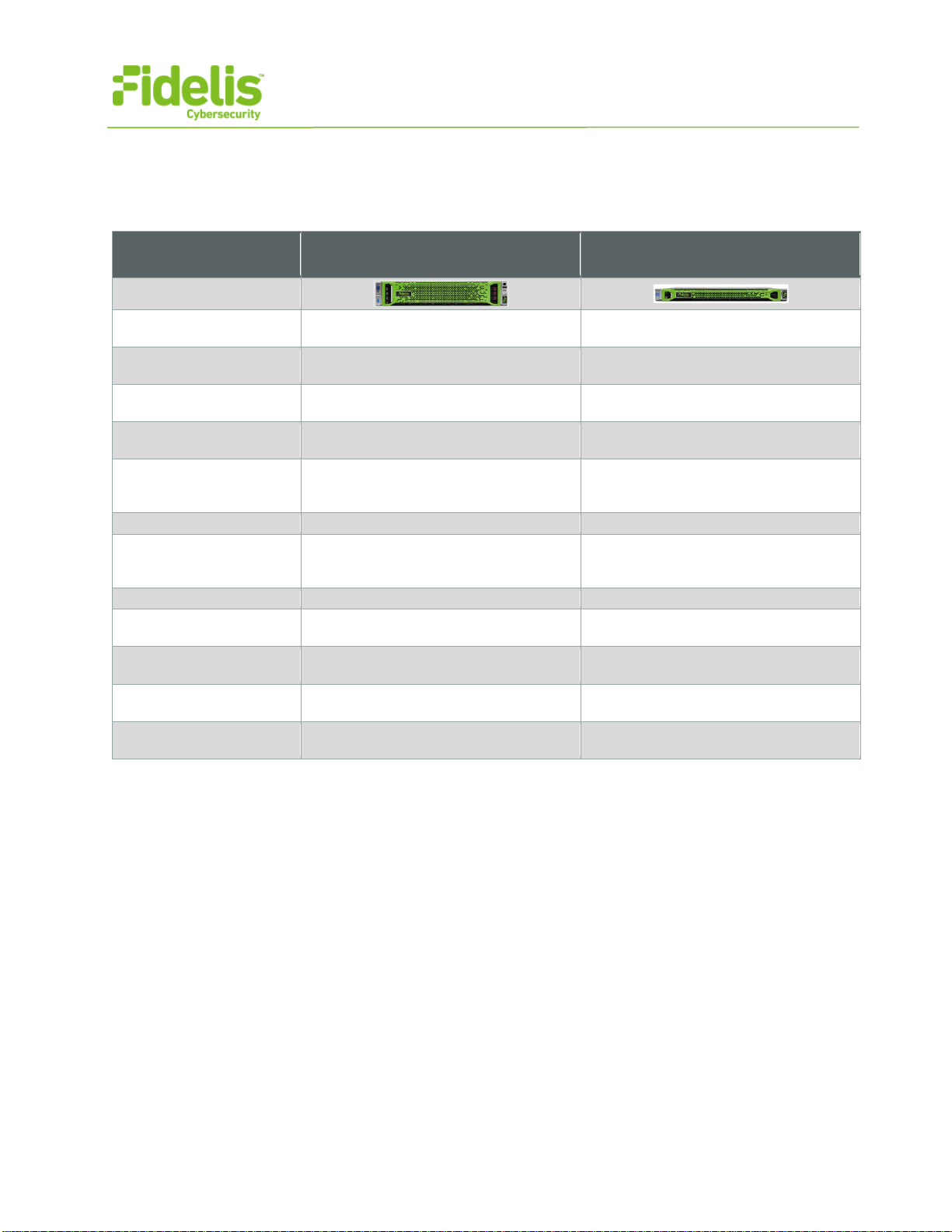
Figure 1: Fidelis Network – Sensor Appliance (1U) Rev-H
Figure 2: Fidelis Network – Direct / Internal 10G Sensor Appliance – Rev-H
Fidelis Sensors report network alerts and network metadata to your on-premises Fidelis Network
Enterprise CommandPost appliance - or - to the remote Fidelis Network Cloud. Your configuration
will depend on which environment you are working with. The following instructions will indicate if they
apply to Enterprise (on-prem), Fidelis Network Cloud, or All Environments.
2. Documentation & References
Fidelis Network product documentation, appliance specifications, and instructions can be found at
http://fidelisssecurity.com/customer-support/login or through the icon in the CommandPost GUI.
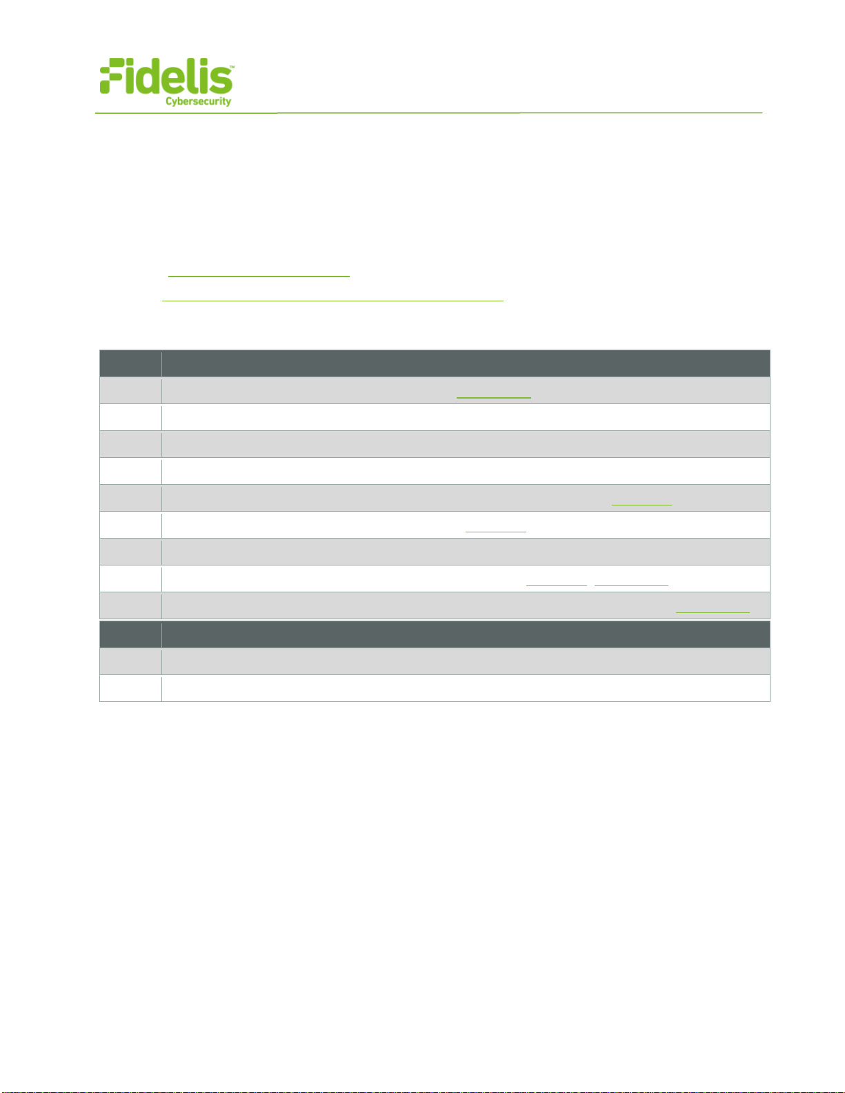
Appliance Default Passwords
System
Account
Default Password
SSH / Appliance Console
fidelis fidelispass
CommandPost GUI
admin
root
ILO
administrator (printed on label, top of server)
QUICK START GUIDE
Fidelis Network™ Sensor Appliances
www.fidelissecurity.com©Fidelis Cybersecurity
3
Technical Support
For all technical support related to this product, check with your site administrator to determine
support contract details. For support of your product, contact your reseller. If you have a direct
support contract with Fidelis Cybersecurity, contact the Fidelis Cybersecurity support team at:
•Phone: +1 301.652.7190
•Toll-free in the US: 1.800.652.4020 – Use the customer support option.
•Email: support@fidelissecurity.com
•Web: http://www.fidelissecurity.com/customer-support/login
Sensor Setup Checklist
Check
Fidelis Network Sensor – Appliance Requirements
Appropriate rack space, power, and cooling (Appendix B)
Rack tools, rails, and connectors
Keyboard and video monitor / KVM switch for temporary appliance setup
Power cables — two per appliance, appropriate for power source and region
Ethernet cables (cat5 and optical) for Admin, Monitor, and iLO ports (Section 3)
Network switches with enough physical ports (Section 4)
Optical transceivers for switches
Logical network information: IP addresses, hostnames (Section 5, Appendix A)
For Fidelis Network Software version 8.3.4 and later, the appliance system type (Appendix C)
Check
…also needed for Fidelis Network Cloud
Connection information from Fidelis Customer Support
Fidelis Network Cloud - Quick Start Guide
QUICK START GUIDE
Fidelis Network™ Sensor Appliances
www.fidelissecurity.com©Fidelis Cybersecurity
4
3. Sensor: Network Port and Cabling Requirements
Fidelis Network Sensors are designed to process different traffic capacities and different types of
network connections, including: 1GbE, 10GbE, 1Gb-SX, and 10Gb-SR. Each appliance must be
connected to the various networks with appropriate cables and in some cases, SFP+ transceivers.
The tables below describe the physical connection and cable type associated with each port on the
appliance.
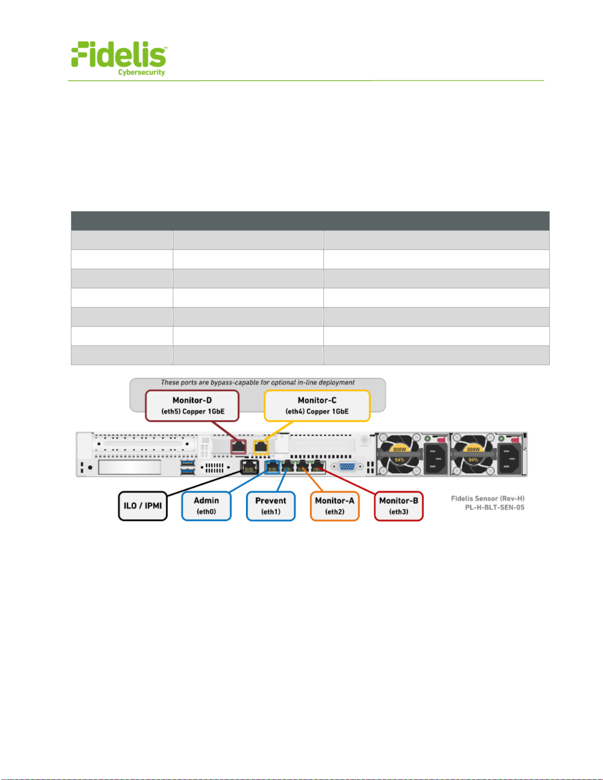
Direct/Internal Appliances With 1GbE rj45/Copper Ports
Cable Type
Admin
8P8C "RJ45" (copper) Cat 5/5e/6 patch cable
Prevent
8P8C "RJ45" (copper) Cat 5/5e/6 patch cable
Monitor-A
8P8C "RJ45" (copper)
Cat 5/5e/6 patch cable
Monitor-B
8P8C "RJ45" (copper) Cat 5/5e/6 patch cable
Monitor-C
8P8C "RJ45" (copper)
Cat 5/5e/6 patch cable
Monitor-D
8P8C "RJ45" (copper) Cat 5/5e/6 patch cable
ILO
8P8C "RJ45" (copper)
Cat 5/5e/6 patch cable
Figure 3: Rear Port Assignments — Sensors rated up to 1Gbps (Direct, Internal, Mail, and Web)
QUICK START GUIDE
Fidelis Network™ Sensor Appliances
www.fidelissecurity.com©Fidelis Cybersecurity
5
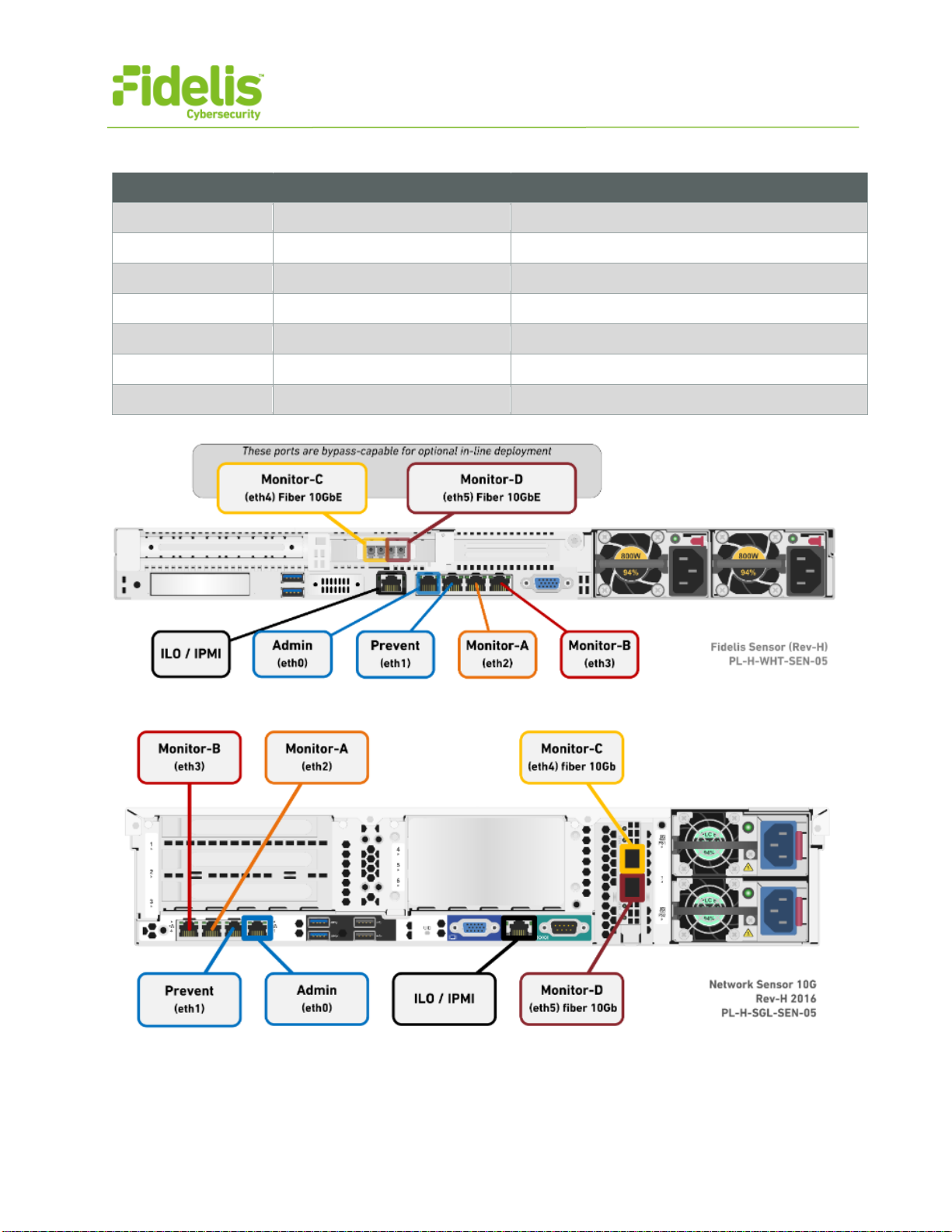
Direct/Internal Sensor Appliances With 10GbE Optical Ports
Cable Type
Admin
8P8C "RJ45" (copper) Cat 5/5e/6 patch cable
Prevent
8P8C "RJ45" (copper) Cat 5/5e/6 patch cable
Monitor-A
8P8C "RJ45" (copper) Cat 5/5e/6 patch cable
Monitor-B
8P8C "RJ45" (copper) Cat 5/5e/6 patch cable
Monitor-C
LC Connector Fiber SR Patch Cable, Multimode 850nM
Monitor-D
LC Connector Fiber SR Patch Cable, Multimode 850nM
ILO
8P8C "RJ45" (copper)
Cat 5/5e/6 patch cable
Figure 4: Rear Port Assignments — Direct/Internal 2500, 5000
Figure 5: Rear Port Assignments — Direct 10G & Internal 10G
QUICK START GUIDE
Fidelis Network™ Sensor Appliances
www.fidelissecurity.com©Fidelis Cybersecurity
6
4. Sensor Networking Environment
Sensor appliances may connect to multiple networks for service and monitoring. Use the tables
below to identify how many and what type of network switch ports you will need for your deployment.
Admin Network
The Admin Network connects Fidelis Network Sensors to the CommandPost, Collector, and
Sandbox. You need one switch port per Sensor appliance for the Admin network.
Appliance
Switch Port Type
Qty.
All Sensors
8P8C "RJ45" (copper)
Prevent Network
Optional connection that the Sensor uses to deliver TCP Reset and other messages to the
production environment. This connection is only used if the Sensor is connected out-of-band to one
or more monitored networks. If you use the Prevent port, you will need one additional switch port per
Sensor.
Appliance
Switch Port Type
Qty.
All Sensors
8P8C "RJ45" (copper)
Monitor A and Monitor-B Networks
Optional ports to connect the Sensor appliance to the monitored networks "A" and "B" through
network switch mirrored-ports or taps. One additional port for each monitored network.
Appliance
Switch Port Type
Qty.
All Sensors
8P8C "RJ45" (copper)
Monitor C and Monitor-D Networks
Most environments use the Monitor-C and -D ports (instead of -A and -B) because these ports offer
support for higher network throughput and/or support in-line session blocking and prevention / policy
enforcement.
For in-line prevention, connect both Monitor-C and Monitor-D to the same monitored network to
allow network data to flow through the device. You will need two switch ports for monitoring in-line.
Note: Direct/Internal 10G Sensor does not support in-line configuration.
In the out-of-band configuration, connect the Sensor appliance to the monitored networks "C" and
"D" through network switch mirrored-ports or taps. One additional port for each monitored network.
Appliance
Switch Port Type
Qty.
GbE Sensors
8P8C "RJ45" (copper)
2.5-, 5-, and 10-Gb Sensors
LC Connector (may require SFP+ transceiver)
QUICK START GUIDE
Fidelis Network™ Sensor Appliances
www.fidelissecurity.com©Fidelis Cybersecurity
7
ILO / IPMI Network
Optional network for remote/out-of-band server administration. You will need one additional switch
port for each IPMI connection.
Appliance
Switch Port Type
Qty.
All Sensors
8P8C "RJ45" (copper)
5. Appliance — Logical Network Configuration
Each physical connection must be assigned logical network information. Build a table of the logical
information for each appliance (example below) that you can reference during configuration.
Appendix A includes a worksheet for you. You will reference this table multiple times during setup.
Direct/Internal Sensor Appliances With 10GbE Optical Ports
Network Setting Assignments
Interface Admin Prevent Mon-A Mon-B Mon-C Mon-D ILO / IPMI
Hostname (FQDN) sensor1.myorganization.int
Static IP Address 10.1.2.3 172.16.1.254 n/a* n/a* n/a* n/a* 10.2.3.4
Subnet Mask 255.255.255.0 255.255.255.0 n/a* n/a* n/a* n/a* 255.255.255.0
Gateway 10.1.2.1 172.16.1.1 n/a* n/a* n/a* n/a* 10.2.3.1
Proxy Server 10.5.6.7
DNS Servers 8.8.4.4, 8.8.8.8
NTP Servers 0.pool1.ntp.org.
Time Zone UTC (+0)
*For Alternative Sensor Network Configurations - In-line & ERSPAN
This Quick Start Guide will help you configure a Sensor in "tap" or "out-of-band" mode, where each
monitoring interface is connected to a different network. In out-of-band mode, each monitor port is
configured in promiscuous mode, and therefore do not need IP network information. Sensors may
alternatively be configured in-line with the network traffic or support ERSPAN, which may require IP
network configuration. For help with these configurations, please see the Fidelis Network
Enterprise Setup Guide.
QUICK START GUIDE
Fidelis Network™ Sensor Appliances
www.fidelissecurity.com©Fidelis Cybersecurity
8
6. Appliance Installation
Rack Installation
Install each appliance in an enclosure/location that has necessary power and cooling. Ensure that
the installation environment is within the operating temperature of the appliance.
Refer to Appendix B for appliance operating temperature requirements.
Power
Connect power cables to the power supplies in the back of the appliance.
See Appendix B for appliance power specifications.
Network Cabling
Using the connectors and cables described in sections 3 and 4, begin to connect the appliances to
the networks. Cable the Sensor appliances to the switches:
1. Connect Admin (eth0) port to the ADMIN switch port.
2. Connect the iLO port to the ADMIN (or ILO) switch port (optional).
7. Appliance Network Configuration
1. Power on the Appliance(s).
2. Connect to the component CLI using one of the following methods:
−Via SSH: Directly attach an Ethernet cable
from a client system such as a laptop to the
Admin/eth0 port on the appliance. The default
IP address is 192.168.42.11/24. Assign a static
IP from the same subnet to the network
interface on the client system and connect to
the appliance using SSH.
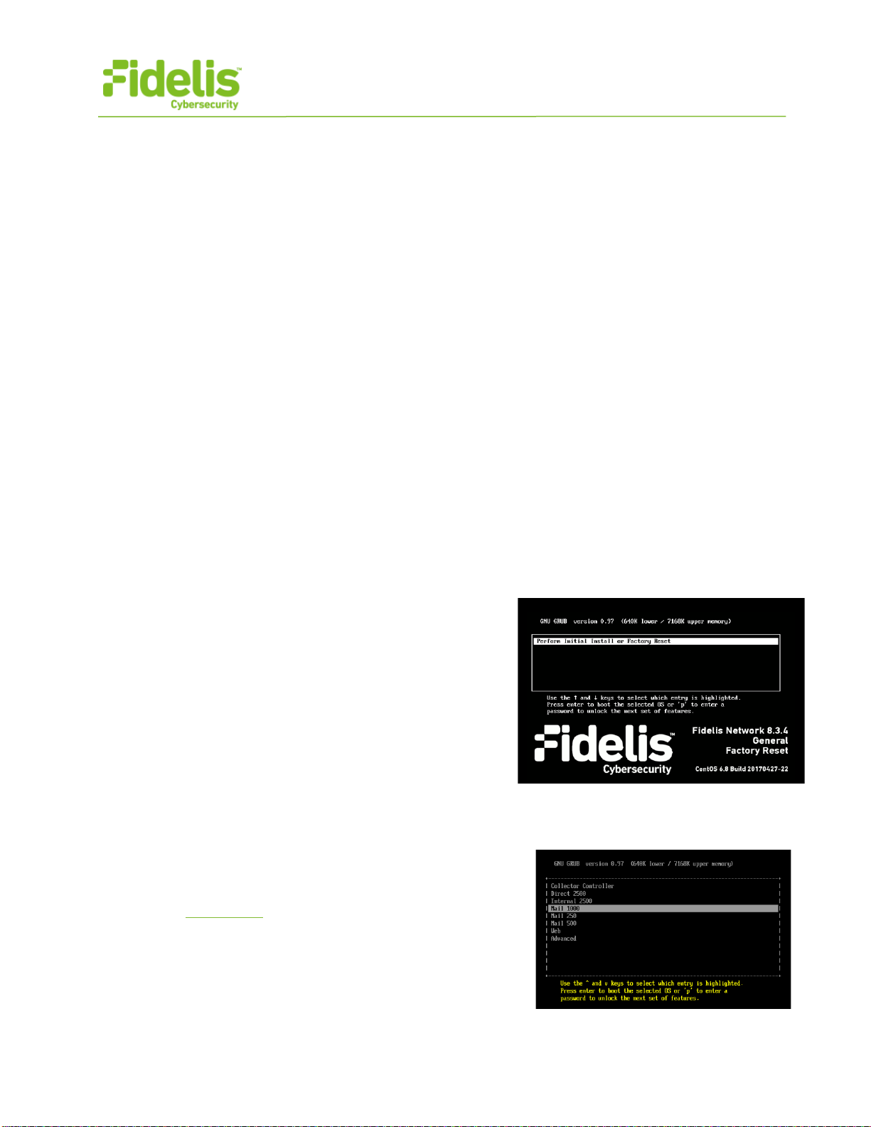
−Via KVM Console: Connect a keyboard and
monitor to the appliance.
For Fidelis Network appliances version 8.3.4 or
later, the screen on the right is displayed:
3. If you see the screen above, perform thefollowingsteps to apply the software. Otherwise skip to step 4.
a. With [Perform Initial Install or Factory Reset] selected, press Enter.
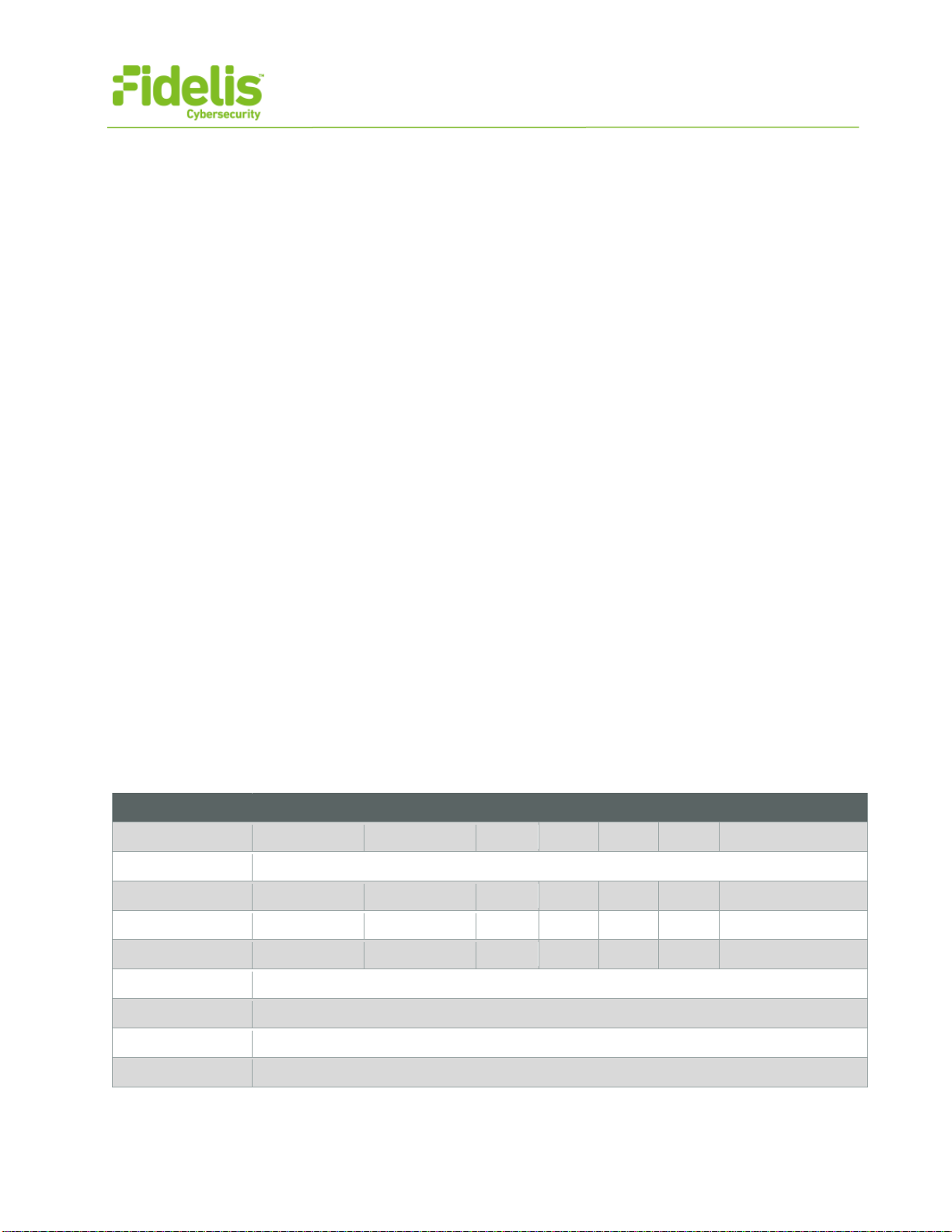
b. Use the Up and Down arrow keys to select the
system type, and press Enter.
If you need help determining the system type, see
Appendix C.
The system displays a screen with the message
“Congratulations, your CentOS installation is
complete.
c. Click Reboot.

QUICK START GUIDE
Fidelis Network™ Sensor Appliances
www.fidelissecurity.com©Fidelis Cybersecurity
9
4. Use these credentials at the login prompt:
−user: fidelis
−default password: fidelispass
5. From the command line, run: sudo /FSS/bin/setup
You will be prompted for the SU (fidelis) password
6. Within Setup, select Network Settings.
7. Configure the network parameters for the system and each active network interface.
a. Use the Network Configuration table you prepared earlier.
b. When complete, return to the top menu.
8. When complete, select [OK] to leave Setup.
9. From command line, reboot the system: sudo /fss/bin/shutdown.pl --user admin --reboot
8. Fidelis Network Integration — Enterprise CommandPost
Environments
Register Sensor Appliances with Your Fidelis Enterprise CommandPost
1. Log into the CommandPost GUI from a web browser.
2. Navigate to the System > Configuration Wizard page.
3. Click [Add] Sensor. Complete the form:
−Component Name — this is a user-friendly name for the Sensor, not the FQDN of the Sensor
−Component IP address — the IP address of the ADMIN interface of the Sensor appliance
−Description — an optional label for the component e.g. location, business unit, etc.
−click [Add].
4. The Sensor's Component Name will appear on the list below Direct/Internal. Click on the
Component Name to view the Component Details.
5. Click [Register] and accept the End User License Agreement (EULA). CommandPost will
then communicate with the Sensor at the specified IP address.
9. Fidelis Network Integration - Fidelis Network Cloud
Environments
Register Sensor Appliances with Fidelis Network Cloud
Please contact Fidelis Support to connect your Sensors to the Fidelis Network Cloud. Fidelis
Support will work with you to configure the Sensors and enable the Fidelis Network Cloud for your
environment.
QUICK START GUIDE
Fidelis Network™ Sensor Appliances
www.fidelissecurity.com©Fidelis Cybersecurity
10
10. Fidelis Licensing
The CommandPost GUI shows the Host ID for the Fidelis Network hardware, the current license
key, and the expiration date. To access the License page:
1. Log into the CommandPost.
2. Click System>Components>[component name]>Config.
3. Click the License tab.
If your license key shows <no license> or <invalid>. Refer to Request a License for more information.
Request a License
1. Click Request License or click the Host ID to start an email to license@fidelissecurity.com
that includes the product type, serial number, and Host ID.
2. Include in the body of the email:
−contact name and phone number
−organization name and site location
Fidelis Cybersecurity will respond within one business day with a license key.
Enter a License Key
After receiving a response to a license request:
1. Copy the license key exactly into the License Key box.
2. Click Save.
When complete, the Fidelis Sensor is operational and ready to monitor the network.
Appendix A: Network Configuration Worksheet
Sensors (All Types)
Network Setting
Assignments
Interface
Admin
Prevent
Mon-A
Mon-B
Mon-C
Mon-D
ILO / IPMI
Hostname (FQDN)
Static IP Address
Subnet Mask
Gateway
Proxy Server
DNS Servers
NTP Servers
Time Zone
* For in-line or ERSPAN deployments, see the Fidelis Network Enterprise Setup Guide.
QUICK START GUIDE
Fidelis Network™ Sensor Appliances
www.fidelissecurity.com©Fidelis Cybersecurity
11
Appendix B: System Specifications
Direct/Internal 10G & 5000
Direct/Internal
10G Direct/Internal
5000
Form Factor 2U rack-mount chassis
1U rack-mount chassis
SFF
CPU
Quad Intel Xeon v3
18-core 2.1 Ghz
Dual Intel Xeon v3
14-core 2.6 Ghz
Memory
256 GB
ECC DDR4 2133Mhz
128 GB
ECC DDR4 2133Mhz
Storage Capacity &
Configuration
500 GB
2x HDD, RAID-1
300 GB
2x HDD, RAID-1
Network Adapters 4x 1GbE
2x 10GbE optical
4x 1GbE
2x 10GbE optical
(inline capable)
Out of Band Management
Integrated Lights Out Management (ILO)
Integrated Lights Out Management (ILO)
Dimensions
H: 8.73 cm ( 3.44 in)
W: 44.55 cm (17.54 in)
D: 73.60 cm (28.97 in)
H: 4.32 cm ( 1.7 in)
W: 43.47 cm (17.1 in)
D: 69.85 cm (27.5 in)
Weight (appx.)
32.18 kg (70.94 lb)
15.6 kg (35.5 lb)
Power Supply
Dual hot-swap 1200W
High Efficiency AC power supplies
Dual hot-swap 800W
High Efficiency AC power supplies
Operating Temperature
10° to 35°C (50° to
95°F) at sea level
10° to 35°C (50° to
95°F) at sea level
AC input Requirements
100 – 120 VAC
200 – 240 VAC
100 – 120 VAC
200 – 240 VAC
BTU Rating (max)
3408 BTU/hr (120 VAC)
4500 BTU/hr (230 VAC)
3207 BTU/hr (100 VAC)
3071 BTU/hr (200 VAC)
QUICK START GUIDE
Fidelis Network™ Sensor Appliances
www.fidelissecurity.com©Fidelis Cybersecurity
12
Direct/Internal 2500, 1000 & 500
Direct/Internal
2500 Direct/Internal
1000 & 500
Form Factor
1U rack-mount chassis
SFF
1U rack-mount chassis
SFF
CPU
Dual Intel Xeon v3
10-core 2.6 Ghz
Dual Intel Xeon v3
8-core 2.6 Ghz
Memory
96 GB
ECC DDR4 2133Mhz
64 GB
ECC DDR4 2133Mhz
Storage Capacity &
Configuration
300 GB
2x HDD, RAID-1
301 GB
2x HDD, RAID-1
Network Adapters
4x 1GbE
2x 1GbE
(inline capable)
4x 1GbE
2x 10GbE optical
(inline capable)
Out of Band Management
Integrated Lights Out Management (ILO)
Integrated Lights Out Management (ILO)
Dimensions
H: 4.32 cm ( 1.7 in)
W: 43.47 cm (17.1 in)
D: 69.85 cm (27.5 in)
H: 4.32 cm ( 1.7 in)
W: 43.47 cm (17.1 in)
D: 69.85 cm (27.5 in)
Weight (appx.)
15.6 kg (35.5 lb)
15.6 kg (35.5 lb)
Power Supply
Dual hot-swap 800W
High Efficiency AC power supplies
Dual hot-swap 800W
High Efficiency AC power supplies
Operating Temperature
10° to 35°C (50° to
95°F) at sea level
10° to 35°C (50° to 95°F) at sea level
AC input Requirements
100 – 120 VAC
200 – 240 VAC
101 – 120 VAC
200 – 240 VAC
BTU Rating (max)
3207 BTU/hr (100 VAC)
3071 BTU/hr (200 VAC)
3208 BTU/hr (100 VAC)
3071 BTU/hr (200 VAC)
QUICK START GUIDE
Fidelis Network™ Sensor Appliances
www.fidelissecurity.com©Fidelis Cybersecurity
13
Direct 250, 100, & 50 and Mail 1000, 500, & 250 and Web
Direct
250, 100, & 50 Mail 1000, 500 & 250
and Web
Form Factor
1U rack-mount chassis
SFF
1U rack-mount chassis
SFF
CPU
Intel Xeon v4
4-core 2.6 Ghz
Dual Intel Xeon v3
10-core 2.6 Ghz
Memory
16 GB
ECC DDR4 2400Mhz
96 GB
ECC DDR4 2133Mhz
Storage Capacity &
Configuration
300 GB
2x HDD, RAID-1
300 GB
2x HDD, RAID-1
Network Adapters
4x 1GbE
2x 1GbE
(inline capable)
4x 1GbE
2x 10GbE optical
(inline capable)
Out of Band Management
Integrated Lights Out Management (ILO)
Integrated Lights Out Management (ILO)
Dimensions
H: 4.32 cm ( 1.7 in)
W: 43.47 cm (17.1 in)
D: 69.85 cm (27.5 in)
H: 4.32 cm ( 1.7 in)
W: 43.47 cm (17.1 in)
D: 69.85 cm (27.5 in)
Weight (appx.)
15.6 kg (35.5 lb)
15.6 kg (35.5 lb)
Power Supply
Dual 900W
High Efficiency AC power supplies
Dual hot-swap 800W
High Efficiency AC power supplies
Operating Temperature 10° to 35°C (50° to 95°F) at sea level
10° to 35°C (50° to
95°F) at sea level
AC input Requirements
100 – 120 VAC
200 – 240 VAC
100 – 120 VAC
200 – 240 VAC
BTU Rating (max)
3207 BTU/hr (100 VAC)
3071 BTU/hr (200 VAC)
3207 BTU/hr (100 VAC)
3071 BTU/hr (200 VAC)

QUICK START GUIDE
Fidelis Network™ Sensor Appliances
www.fidelissecurity.com©Fidelis Cybersecurity
14
Appendix C: System Types
For Fidelis Network Software version 8.3.4 and later, the table below shows the software to apply
based on the appliance SKU. You can find the SKU in the following locations:
(Note that the SKU starts with “FSS”.)
•Appliance lid UID decal (see sample on right)
•Shipping carton UID decal (see sample on right)
•Packing list
•Purchase Order
Appliance SKU starts with:
System Type
Example
FSS-DIR-<number> Direct <number> FSS-DIR-2500 = Direct 2500
FSS-INT-<number>
Internal <number>
FSS-INT-5000 = Internal 5000
FSS-MAIL-<number> Mail <number> FSS-MAIL-250 = Mail 250
FSS-Web
Web
FSS-Web = Web
QSC_Fidelis_Sensor_20170524
This manual suits for next models
11
Table of contents
Popular Firewall manuals by other brands


NETGEAR
NETGEAR ProSafe FVS318N Reference manual

Draytek
Draytek Vigor2830 Series user guide

Fortinet
Fortinet FortiGate-200A Administration guide

Fortinet
Fortinet FortiGate-300C quick start guide

PaloAlto Networks
PaloAlto Networks PA-400 Series Hardware reference

Fortinet
Fortinet FortiGate FortiGate-3600A quick start guide

PaloAlto Networks
PaloAlto Networks PA-7050 PAN-AIRDUCT Hardware reference guide

Clavister
Clavister Eagle E20 Getting started guide

Excelsecu Data Technology Co., Ltd.
Excelsecu Data Technology Co., Ltd. eSecu FIDO2 user manual

Lanner
Lanner NCA-5530 user manual

NETGEAR
NETGEAR ProSafe FVS318v3 Reference manual

Juniper
Juniper SRX5600 quick start guide