Fidelity Measurement DM-180 SERIES User manual

1
DM-180 SERIES
DIGITAL WEIGHING SCALE
OPERATION MANUAL
PLEASE READ THIS MANUAL VERY CAREFULLY BEFORE ATTEMPT
TO OPERATE THIS SCALE
V100 Feb 2013
Specifications subject to change without prior notice

2

3
CONTENT
1. Before Started........................................................................................... 5
1.1 Metrological Legislation...................................................................... 5
1.2 Seal & Serial Number......................................................................... 5
1.3 Warm Up Time.................................................................................... 5
1.4 In Case When In Doubt...................................................................... 5
2. Specifications............................................................................................ 6
3. Keys, Display & Connections.................................................................... 7
4. Getting Started.........................................................................................11
4.1 Built-In Rechargeable Battery ...........................................................11
4.2 Power Adaptor...................................................................................11
4.3 Connecting Other Devices ................................................................11
4.4 Setting Up The Preferred Operation Parameters............................. 12
5. Initial Setup............................................................................................. 13
5.1 Internal Settings................................................................................ 13
5.2 How To Enter And Select Internal Function...................................... 13
5.3 Key Function During Internal Function Mode................................... 14
5.4 Internal Function Table..................................................................... 14
6. Instruction for Use................................................................................... 19
6.1 Power On.......................................................................................... 19
6.2 Start Weighing.................................................................................. 19
6.3 About Weigh Unit Conversion .......................................................... 19
6.4 Tare off the Weight of a Container.................................................... 20
6.5 Memory Accumulation Function....................................................... 21
6.6 Piece Count Function....................................................................... 22
6.7 Sampling Process ............................................................................ 23
6.8 Shift among Quantity, Average Piece Weight and Weight Info ........ 23
6.9 To quit Piece Count Function ........................................................... 23
7. RS232 Data Output Mode ...................................................................... 24
7.1 Auto Weight Format String .............................................................. 24
8. Ticket / Receipt Printing.......................................................................... 25
8.1 Standard Print Output Format ......................................................... 25
8.2 Custom Print Output Format ........................................................... 27

4
9. Label Printing (LP-50 or Compatible) ..................................................... 29
9.1 Label Format Groups & Label File Names....................................... 29
9.2 Label Programming.......................................................................... 30
10. Battery Power & Recharging ................................................................ 33
10.1 Symbols And Remaining Power: -.................................................. 33
10.2 Battery Operation Time .................................................................. 33
10.3 Recharge Battery ........................................................................... 33
11. Error Codes........................................................................................... 34
12. Daily Care & Maintenance.................................................................... 35
Appendix A: - Bi-Directional Communication Commands .......................... 36

5
1. Before Started
1.1 Metrological Legislation
Because of metrological legislation, installation and some metrological
parameter settings / changings are limited to be done by authorized
personnel only. Do not attempt to change any of the built-in parameters.
Contact your dealer for installation and technical assistance.
1.2 Seal & Serial Number
This scale is legal for trade only when it is sealed (and/or stamped) and
bearing a serial number. Do not attempt to break the seal (or stamp) or
serial number affixed to scale. Contact your dealer for more information and
after sales service.
1.3 Warm Up Time
a. Allow warm up period of not less than 60 seconds before calibration.
The higher the setup resolution of the scale, the longer the warm up
period is required. In most cases, 120 seconds is a safe warm up
period for all applications.
b. This warm up period is needed to energy all components to reach a
stable status.
c. The internal count value is deemed stable when the internal AD
count varies less than 3 counts within 2 seconds.
d. To read the internal AD count value, enter internal function F1. The
internal AD count value of a not yet fully energized PCB will go up
continuously.
1.4 In Case When in Doubt
Always contact your dealer for more information, after sales service and
questions when in doubt.

6
2. Specifications
Model
Capacity (g)
Readability (g)
DM180-1500B
1500
0.1
DM180-3000B
3000
0.2
DM180-7500B
7500
0.5
DM180-15KB
15000
1
DM180-30KB
30000
2
Weight Units
kg / g / lb (Weight Unit Conversation Supports
Single Range Models only)
Max. Tare Range
- Max (Subtractive Tare)
Platter Cover
220 x 290mm all Stainless Steel
Dual Power Source
•Built-in Rechargeable Battery = 6V, 4AH
•External Power Adaptor = DC 12V, 1A
with Universal Plugs
Operation
Environment
-10 ~ 40oC. Non-condensed. R.H.≦85%
Specifications subject to change prior to notice

7
3. Keys, Display & Connections
0. Spare
Spare key, no assignment.
1. Spare
Spare key, no assignment.
2. Zero Key
Press this key to set weight displayed to zero when an empty scale has
drifted away from a true zero reading.

8
3. Tare Key
Press this key to tare off the weight of a container.
4. Function Key
Press this key to shift between percentage, piece count and animal
1
mode.
5. Unit Key
Press this key to shift among various weight units (if weight unit
conversation is enabled).
6. Print Key
2
Press this key to print the results to a computer or a printer through the
RS-232 output.
7. MR Key
Press this key to recall total stored transactions.
8. M+ Key
Press this key to accumulate current weight to memory manually.
9. Battery Power / Level Indicator
Visible to show: -
•Scale is being powered by the built-in rechargeable battery,
•Remaining battery level.
10. W1Indicator
3
(When under dual weighing range mode
4
) Visible when scale is in the first
weighing range (W1).
1
When F11 = ON.
2
This key is also used to accumulate the current weight value to memory when internal
function F17 is set to ON.
3
This indicator will not appear when scale is in single range mode.
4
Scale can support two weighing ranges with different maximum capacities (Max) and
different scale intervals (d), each range extending from zero to its maximum capacity.

9
11. W2Indicator
5
(When under dual weighing range mode) Visible when scale is in the
second weighing range (W2).
12. Minus Sign
Visible when a negative value is displayed.
13. Gross Indicator
Visible when gross weight reading is displayed.
14. Net Indicator
Visible when the tare function is in effect. Weight reading shown is net
value.
15. Stable Indicator
Visible when weight reading is stable.
16. Zero Indicator
Visible when instrument is at true zero weight status.
17. M+ Indicator
Visible when memory contains of accumulated data.
18. MR Indicator
Visible when the total accumulated weight value is displayed.
19. Weight Units and Functions
•kg = kilogram,
•PCS = Pieces (Piece Count Mode in function),
•kg/PCS and g/PCS = Weight per piece (when Piece Count Mode in
function),
•lb = pound.
5
This indicator will not appear when scale is in single range mode.

10
20. Charge Status Indicator
•Red color: Recharging battery,
•Green color: Charging completed
BOTTOM VIEW
A. On/Off Key
Press this key to turn this scale on or off.
B. DC Jack Input
External power adaptor is plugged in here. Output requirements of the
power adaptor: -
•DC9 ~ 12V 800mA,
•Polarity: - Any kind.
C. RS232 Comport (DB9)
RS232 communication comport.

11
4. Getting Started
In order to obtain an accurate weighing result, this scale must be placed on
a strong and level surface. Avoid using this scale in environment where
excessive wind flow, vibration and extreme temperature change exist
General Warning: -
This scale is not an explosion proof device.
This scale is not a water proof device.
Do not open this scale, no user serviceable parts inside. Always
contact your dealer for service.
This scale not to be subject to shock, excessive vibration or
extremes of temperature (before or after installation).
4.1 Built-In Rechargeable Battery
This scale is equipped with a built-in rechargeable battery. Before first time
use, recharge it for at least 8 hours to ensure the best battery performance.
4.2 Power Adaptor
One universal voltage power adaptor with 4 power plugs are supplied with
scale. Select the suitable power plug and slide it into the power adaptor
very carefully until a "click" sound comes out.
4.3 Connecting Other Devices
6
4.3.1 Before Connecting with others
Turn this scale off and cut off power before making any connections or
disconnections.
6
Turn scale off before making any connections or disconnections.
12
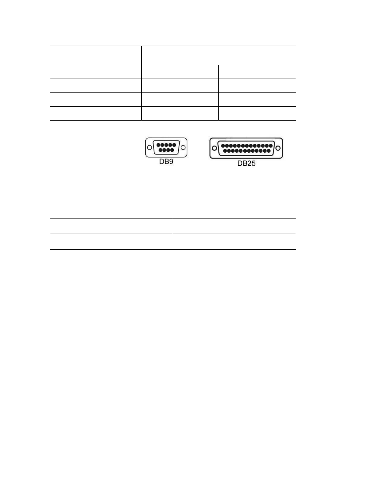
4.3.2. Connecting RS232 to computer
RS232 COMPORT
COM PORT ON COMPUTER
(DB9)
(DB25)
2 = RXD
3 = TXD
3 = TXD
3 = TXD
2 = RXD
2 = RXD
5 = GND
5 = GND
7 = GND
4.3.3 Connecting RS232 to Printer (DB25)
RS232 COMPORT (DB9) ON
SCALE
COMPUTER COM DB25
2 = RXD
3 = TXD
3 = TXD
2 = RXD
5 = GND
7 = GND
4.4 Setting Up the Preferred Operation Parameters
Set all preferred operation parameters according to 5.4 INTERNAL
FUNCTION TABLE.
Note: -
1. F1 ~ F29 are accessible without restriction,
2. F60 ~ F66 are restricted functions which may request a password or
hardware key to access,
3. F80 ~ F99 are restricted functions, which may request a password or
hardware key to access. These functions are usually for dealer and
authorized personnel only. Do not change any settings of these
functions to avoid operation errors.

13
5. Initial Setup
5.1 Internal Settings
Application parameters can be checked or set through internal setting
functions. Refer to 5.4 for description of all internal functions.
5.2 How To Enter And Select Internal Function
Follow the below steps to enter and select desired parameter of an internal
function.
Follow the below steps to enter and select desired parameter of an internal
function.
(For F60 ~ F99) If Setup & Calibration Control Jumper is set to enable
position (B & C), instrument will enter internal function automatically after
power on.
Should password mode be used to bypass this jumper, follow the below
steps to enter and select desired parameter of an internal function.
a. Power scale off and then power on again,
b. Press [Tare] during countdown,
c. Displays F1,
d. Scale is now in internal function.

14
5.3 Key Function During Internal Function Mode
Key
Function in Setup & Calibration
[On/Off]
Quit without saving and power off
[Zero]
Quit without saving
[Tare]
Go to internal function during power on countdown or set F1
value being shown to zero and to display the net span gain
by applying additional load applied.
[Func]
•Goto next page.
•Move cursor to one place right
[Unit]
•Goto previous page.
•Move cursor to one place left
[Print]
Enter, save and return
[MR]
Clear
[M+]
Increase numeric number by 1
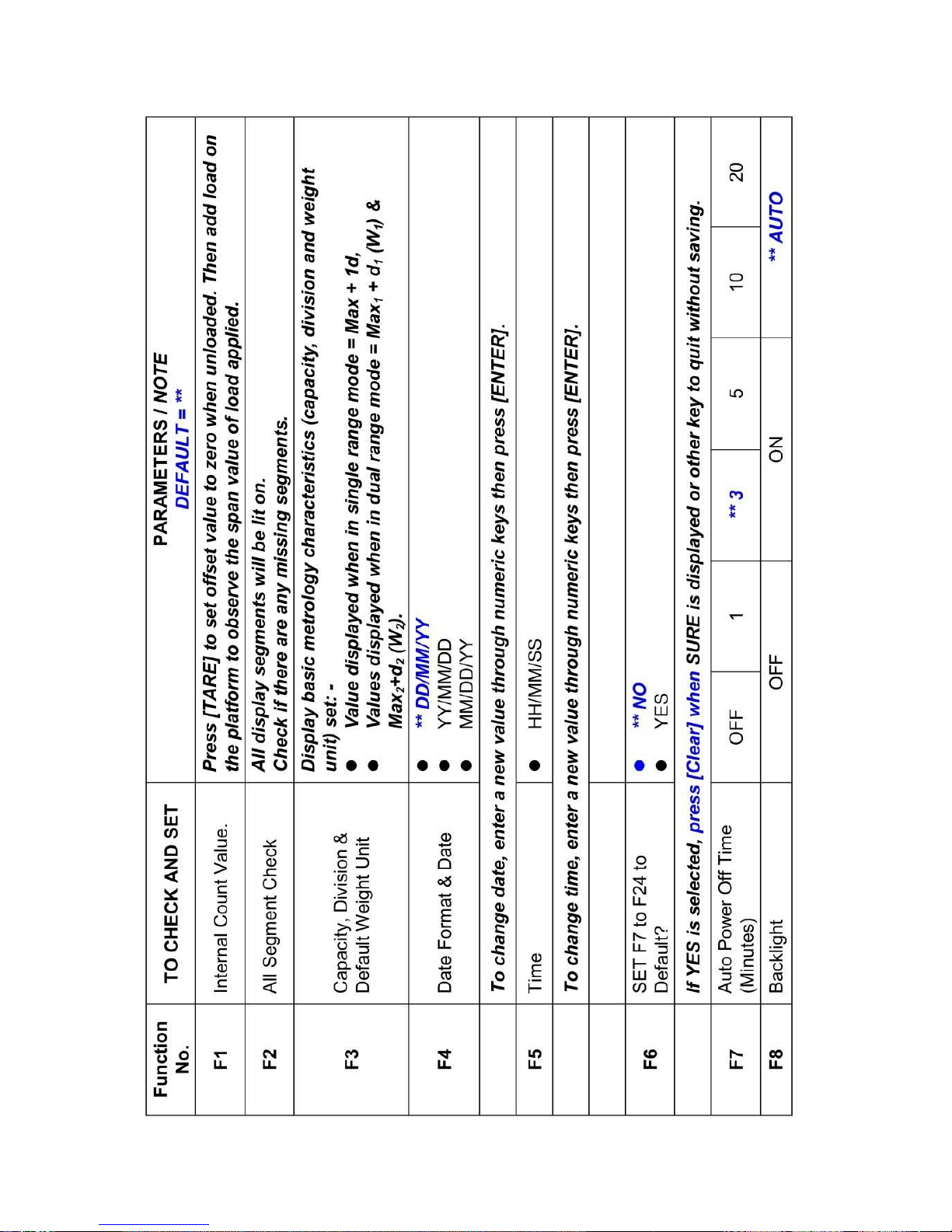
5.4 Internal Function Table
Refer to the below table for internal function number, parameter and setting
notes.
15

16

17

18

19
6. Instruction for Use
6.1 Power On
Powered on scale, it will: -
a. Display software number and revision,
b. Display the calibration count value,
c. Display the parameter set count value,
d. Display all display segments,
e. Scale is now ready for operation.
6.2 Start Weighing
a. If zero weight cannot be obtained when unloaded, press [Zero]. After
[Zero] is pressed, the Zero Indicator will appear.
b. Always place an object onto platform gently. Excessive force applied
to platform may cause damages to the weight sensor,
c. The weight of the object is displayed automatically,
d. It is a good practice to remove all loads from platform after weighing. It
will prolong the life of the weight sensor.
6.3 About Weigh Unit Conversion
The default weight unit is = kg. Depends on the internal settings, scale
supports also g and lb.
6.3.1 Conversion between Metric Weight Units (kg and g)
When 3 or 4 decimal places (0.000 or 0.0000) is selected in F80, reading in
g is possible during normal operation by pressing [Unit] disregarding to the
setting of F9.
The weight unit employed before power off will be employed when powered
on again.
6.3.2 Conversion between Metric (kg and/or g) & Imperial
7
(lb) weight
units (F9)
Scale supports conversion among kg, g and lb. To enable this conversion
7
To comply with the laws of certain countries and approval requirements, the imperial
weight unit may be disabled. Contact your dealer for more information.

20
function, set F9 = ON. Press [Unit] to shift among various weight units.
The weight unit employed before power off will be employed when powered
on again.
6.4 Tare off the Weight of a Container
Tare function is used to temporarily set the scale to zero (such as
cancelling the weight of a box or a container) in order to get the net weight
result
6.4.1 Manual Tare
When a container is used, follow the below steps to tare off the weight of it
and to get a net weight result.
a. Remove all loads from platform,
b. Make sure that the Zero Indicator is on. If not, press [Zero],
c. Place container on platform,
d. Press [Tare] ,
e. Net Indicator appears to indicator tare is in effect and weight
displayed display is net weight.
f. To cancel tare effect, remove all loads from platform and press [Tare],
g. Net Indicator disappears. Gross Indicator appears to indicator tare
effect has been removed and weight displayed display is gross weight.
6.4.2 Auto Tare
8
(F12)
If this function is enabled, scale will assume the first stable weight applied is
a container and will tare off the weight of it automatically.
When container is removed and gross weight result = zero, tare effect will
be cancelled automatically.
6.4.3 Repeated Tare (F13)
9
When F13 is set to OFF, scale does not permit multiple tare operation. Tare
effect can only be cancelled when container is removed and gross weight =
zero.
8
Set F12 = ON to enable Auto Tare Function
9
Set F13 = ON to enable Repeated Tare Function.
Table of contents
Other Fidelity Measurement Scale manuals


