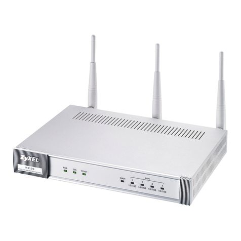
Fidelix FX-AirRECEIVER User manual

-20..55°C
240 x 180 x 33 mm
<5W, 230 VAC
868 MHz (WMBus)
Operation temperature:
Dimensions:
Power consumption:
Communication:
Technical features
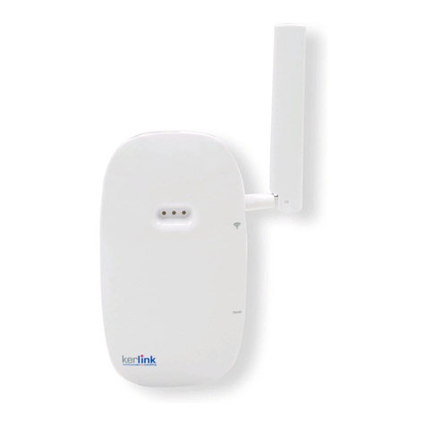
The Fidelix FX-AirRECEIVER is a unit that collects
data from wireless M-Bus devices and oers it to
external Modbus clients as a Modbus TCP-server.
Alternatively, the wireless M-Bus data can be sent
to the cloud by using the 4G/5G network or a
wired landline. The unit has two internal antennas
for improved range. The FX-AirRECEIVER is
meant for indoor installation in residential and
commercial properties and is to be powered
with 230 VAC.
Manage measurements
Amazing radius for wireless M-Bus
Connects easily to Fidelix FX-controllers
or other Modbus TCP clients
Communicate with up to 500 wireless
M-Bus devices
Supports AES128 encrypting
Possibility to send data directly to a
cloud-server via 4G/5G or wired internet
connection
FX-AirRECEIVER
Wireless gateway
wireless

www.
fi
delix.com
Connections, buttons and indicators:
LED
STATUS
GPRS
ETH
9-10 mm
ETH
LN
Min. 5 cm
to wall
Min. 5 cm
to wall
Min. 10 cm
to wall
Min. 10 cm
to wall
FR
1
23 4
6
7 8
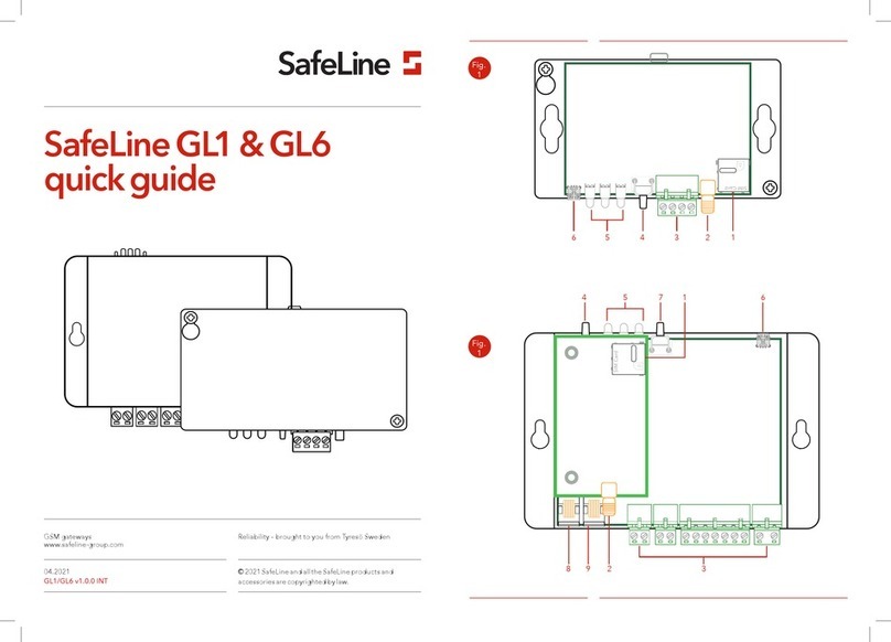
1. LED status (light visible through the casing)
2. Activation button/magnetic sensor for LEDs
3. Factory reset button
4. SIM card holder
5. Product labelling and serial number
6. Power connection (PE is optional)
7. Network connection
8. Strain relief with cable tie.
Physical properties:
Size 240 x 180 x 33 mm
Weight 520 gr
Colour RAL9016
Protection degree IP20 when inlet is facing upwards
IP21 when inlet is facing downwards
Connections:
Power supply connectors Spring-loaded for 0.5-1.5mm2
Supply voltage 230Vac, 50Hz
Power consumption < 5W
Installation category CAT2
Installation conditions:
Location Indoor non-industrial environment
Operation temperature -20 to +55 °C
Ambient temperature -40 to 55 °C
Humidity 10 to 90 %RH non condensing
Max installation height max. 2000 m above sea level
Pollution degree rating Grade 2
Wireless receiver - Wireless MBus:
Wireless M-Bus position T1, S1, C1
Radio frequency 868 MHz
Sensitivity -108 dBm (T1)
Approximate range indoors 50-100m
Supported encryption AES128
Connection - 4G/5G:
LTE Cat M1/NB2
EGPRS 850/900/1800/1900 MHz
Class Maximum Class 12
Antenna Internal
Connection - Ethernet:
Connection RJ45
Cable CAT5 or better
Speed 10/100Mbit, Half-/Full-duplex
Conformity:
Environment RoHS (2011/65/EU) / (EU) 2015/863
Safety RED (2014/53/EU) / IEC 62368-1
Radio / EMC RED (2014/53/EU)
Wireless MBus EN13757-4
Placement:
The indoor range between the Fidelix FX-AirRECEIVER and a
wireless M-Bus transmitter device is normally 50 to 100m.
The range depends largely on the building type and construction
method. In general, the following applies:
• Place the product as centrally as possible with in the area to
be covered. For large areas, multiple receivers or repeaters
may be required.
• Avoid placing in cold areas.
• Avoid placement close to electric cables or other metal
elements. Keep a distance of 20cm around the unit. This also
applies below the unit but obviously not the cables required
to connect the unit.
• The product is constructed to be installed on concrete walls
but a better range is achieved when installed on wood or
drywall.
• New buildings with prefabricated wall elements and low-
energy windows have a strong influence on the wireless
range and can require closer placement to the receiver.

www.
fi
delix.com
Operation:
Start the unit by connecting the power.
The unit’s LEDs are activated for 1-3 minutes flashing a red/green sequence before changing to a fixed light for 10 minutes.
Fixed green light = functioning
Red light = malfunctioning
Description of the LEDs:
The LEDs indicate that the installation is correct as well as confirm that the unit is functioning correctly during its whole lifespan.
The unit has three red and green LEDs. The LEDs are visible through the cover and thus can be seen without opening the unit.
In normal operation, these LEDs are unlit and can be activated by placing a magnet (such as a fridge magnet) on the upper corner
of the unit or by pressing the LED button. After the unit is connected, the LEDs light up for 10 minutes before going out. The LEDs
give information about the status of the unit.
In general, a green light indicates a functioning unit, a red light indicates a fault and a
flashing green/red light indicates that the status is not yet available. An unlit LED means
that the function is inactive e.g. a unit configured for 4G/5G will have an unlit Ethernet
light.
LED indicators:
LED Explanation Visual
Green light Fully functional
Red light Fault
Flashing green/red Status unavailable - wait
Inspection:
Fault Cause Action
The unit’s lights are out. The unit’s lights go out automatically
after 10 minutes.
The unit has no supply voltage.
Place a fridge magnet or similar on the
unit’s upper left corner or activate the
LEDs by pressing the LED button. Check
electrical connection.
The unit’s lights don’t come on when
activated with a magnet.
The magnet is too weak.
The unit has no supply voltage.
Activate the LEDs with the push button.
Check electrical connection.
The unit’s lights don’t come on when
activated with the push button.
The unit has no supply voltage. Check electrical connection.
The unit’s lights don’t go out after 10
minutes.
The unit is mounted on a non-continu-
ous power supply e.g. lighting.
The unit has recently updated its soft-
ware.
Check that the unit is connected to a
continuous power supply.
Units installed with 4G/5G or EGPRS
GPRS light changes to a red light. SIM card missing.
Poor or no 4G/5G coverage.
Check that the unit has a SIM card
installed.
Move the unit to a place with better
coverage.
GPRS light is green, but status is red. No contact with server. Contact the service provider.
Units installed with Ethernet
Ethernet light is red Ethernet link missing. Check the Ethernet cable.
Ethernet light is flashing red No IP address received from DHCP.
Unit configured incorrectly.
Check the connection to the DHCP
server. Contact IT operator.
Change the installation to a static IP.
Ethernet light is green but status is red. No internet connection.
Missing connection to server.
Contact IT operator.
Contact the service provider.
Disposal of product and packaging:
The product’s packaging can be disposed of as corrugated cardboard according to the relevant regulations.
After use, the product is classified as electrical waste and is disposed of according to the relevant regulations. The unit can also be
returned to the manufacturer.
GPRS
Status
Ethernet
