Lütze LOCC-Box-GWPN 0-6457 User manual

Automation Solutions
User Manual
Profinet-IO-Gateway 716457
Description of Profinet-IO-Gateway in connection with
LOCC-Box-Net 716410.
Version 1.00

User Manual Profinet-IO – Gateway
2 Profinet-Gateway 716457_100_HB_EN.docx
The user manual is part of the product and contains important information about the handling and the
safety. To avoid hazardous situations read the manual before installing the product and using it.
Lütze reserves the right to change its products in the interest of technical progress.
These alterations need not to be documented in every case.
This manual and the contained information have been arranged with the utmost care. The Friedrich
Lütze GmbH disclaims liability for literal mistakes and other errors or resulted damages.
The named brands and product names in this document are trademarks or registered trademarks by
title holder.
Copyright 2013 by Friedrich Lütze GmbH. All rights reserved.
Friedrich Lütze GmbH
Post office box 1224
D-71366 Weinstadt - Großheppach
Germany
Phone: +49/ (0)7151/ 6053-0
Fax: +49/ (0)7151/ 6053-277
E-Mail: automatio[email protected]
Internet: http://www.luetze.com

User Manual Profinet-IO - Gateway
Profinet-Gateway 716457_100_HB_EN.docx 3
Content
1 General Information ..................................................................... 5
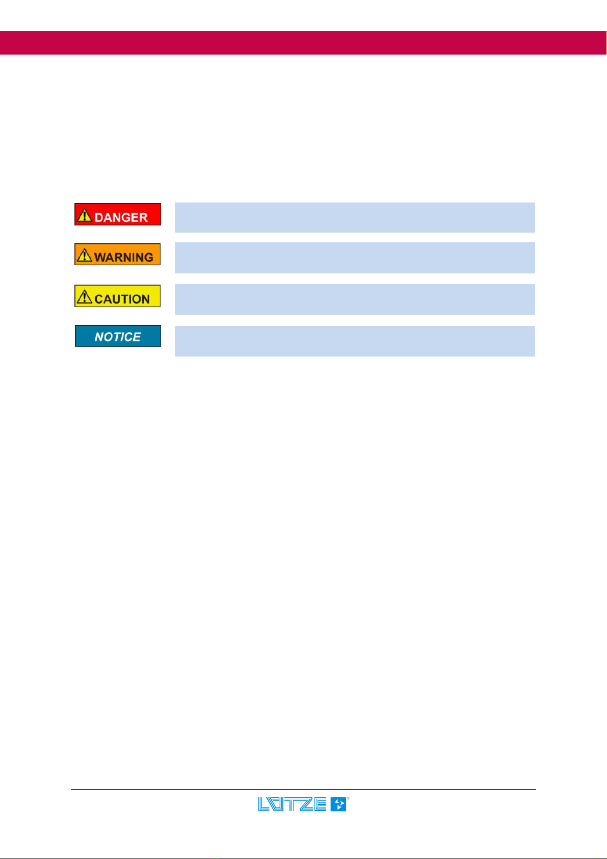
1.1 Symbol Description .............................................................................................. 5
1.2 Copyright .............................................................................................................. 5
1.3 Disclaim of Liability .............................................................................................. 5
1.4 Safety ................................................................................................................... 5
1.4.1 Content of Manual .......................................................................................................... 5
1.4.2 Intended Use ................................................................................................................. 6
1.4.3 Operating Employee ...................................................................................................... 6
1.4.4 Maintenance .................................................................................................................. 6
1.4.5 Decommissioning and Deposal ...................................................................................... 6
2 Gateway – Profinet, 716457 ......................................................... 7
2.1 General Information ............................................................................................. 7
2.1.1 Explanation .................................................................................................................... 7
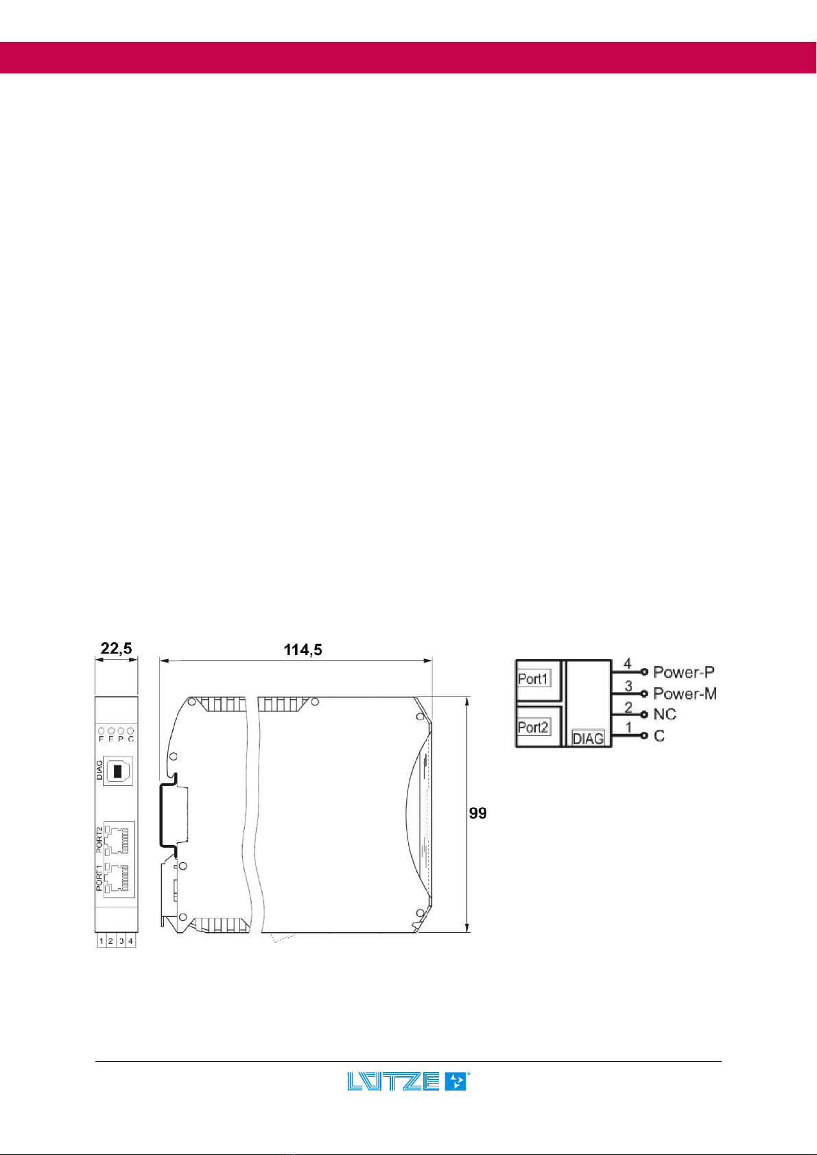
2.1.2 Dimensions and Connections ......................................................................................... 7
2.1.3 Function and Displays .................................................................................................... 8
2.1.4 Topology and Structure .................................................................................................. 8
2.1.5 LOCCbus - Interface ...................................................................................................... 9
2.1.6 Operation system and driver .......................................................................................... 9
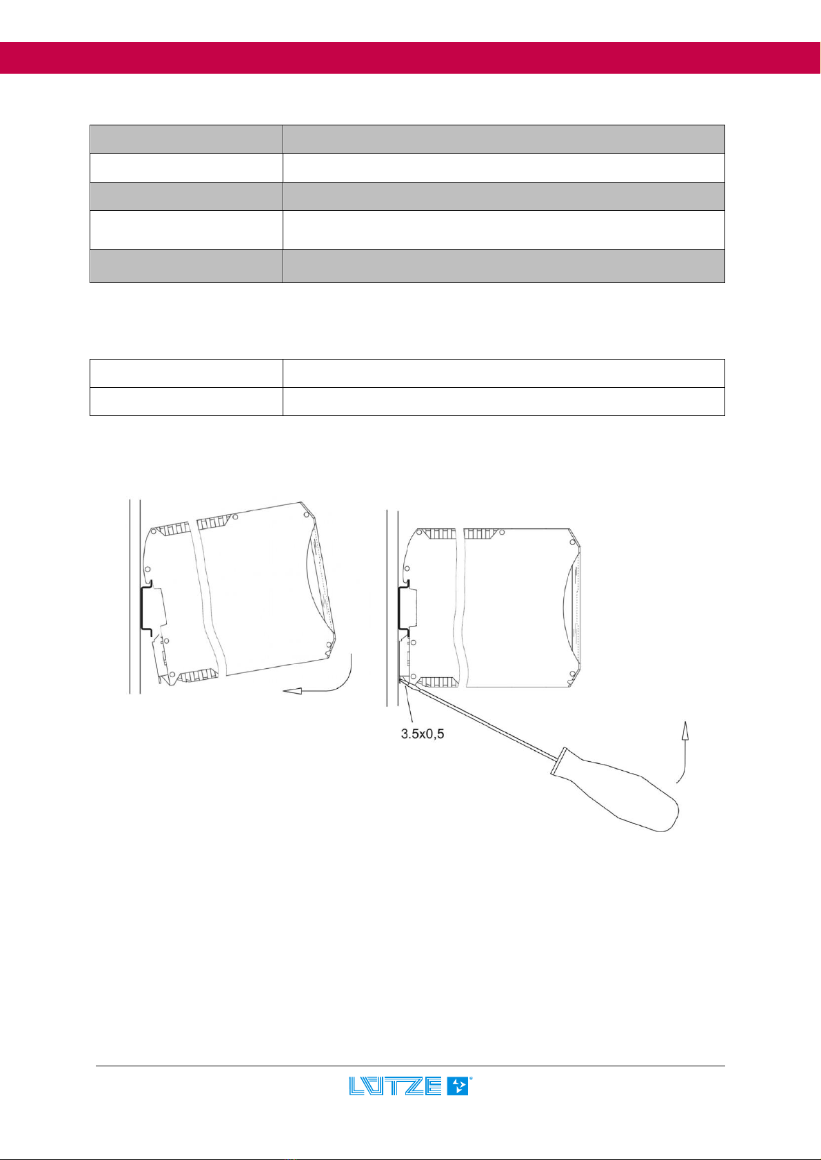
2.1.7 Mounting ........................................................................................................................ 9
2.1.8 Installation ................................................................ Fehler! Textmarke nicht definiert.
2.2 Installation .......................................................................................................... 10
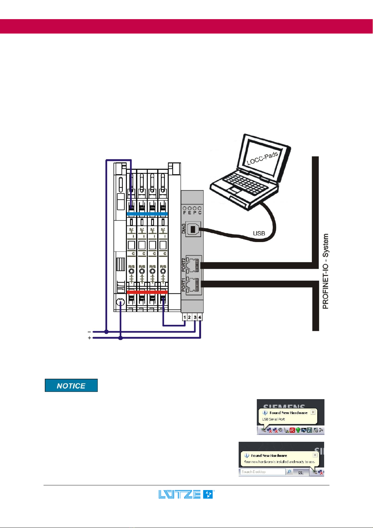
2.2.1 Stracture in principle .................................................................................................... 10
2.2.2 Connection to USB....................................................................................................... 10
2.3 Communication via USB .................................................................................... 11
2.4 Communication via Profinet-IO ......................................................................... 11
2.4.1 Terms and Definitions .................................................................................................. 11
2.4.2 GSDML - Files ............................................................................................................. 12
2.4.3 Profinet-IO Interface ..................................................................................................... 12
2.4.4 Function Range............................................................................................................ 13
2.4.5 Profinet-IO read request (overview of instruction) ......................................................... 13
2.4.6 Configuration in step7 .................................................................................................. 14
2.4.7 Device Access Point (DAP) .......................................................................................... 15
2.4.8 Adjustment of LOCC-Box ............................................................................................. 15
2.4.9 Process Image ............................................................................................................. 15
2.4.9.1 Input-byte ............................................................................................................ 16
2.4.9.2 Output-byte.......................................................................................................... 16
2.4.10 Optional I&M – Services ........................................................................................... 16
2.4.11 Example for the used instructions ............................................................................. 17
2.4.11.1 Module type (2000h) ........................................................................................... 17
2.4.11.2 Module status (2010h) ........................................................................................ 17
2.4.11.3 Module configuration (2011h) ............................................................................. 17
2.4.11.4 Output voltage (2100h) ....................................................................................... 18
2.4.11.5 Input voltage (2101h) .......................................................................................... 18
2.4.11.6 Current Measurement (2104h) ............................................................................ 18
2.4.11.7 Characteristic adjustment (210Ah) ...................................................................... 19
2.4.11.8 Software Version (2200h) ................................................................................... 19

User Manual Profinet-IO – Gateway
4 Profinet-Gateway 716457_100_HB_EN.docx
2.4.11.9 Serial Number (2201h) ....................................................................................... 20
2.4.11.10 LOCC-Box counter “Operating voltage ON“ (2202h) ......................................... 20
2.4.11.11 LOCC-Box Counter “Operating hours (h)” (2203h) ............................................ 20
2.4.11.12 LOCC-Box counter “Operating hours ON (h)“ (2204h) ....................................... 20
2.4.11.13 LOCC-Box counter “Blown” (2205h) ................................................................. 20
2.4.11.14 LOCC-Box Counter “Switch on” (2206h) ........................................................... 21
2.4.12 Siemens – Function Block SFB52 ............................................................................. 21
2.5 Technical Data ................................................................................................... 22
3 Exchanging LOCC-Box-Net without LOCC-Pads ..................... 23
4 Firmware update ........................................................................ 24
4.1 Indroduction ....................................................................................................... 24
4.2 Download ........................................................................................................... 24
4.3 Installation .......................................................................................................... 24
4.4 Update ................................................................................................................ 24
4.5 New hardware installation ................................................................................. 26
5 Accessories ................................................................................ 27

User Manual Profinet-IO - Gateway
Profinet-Gateway 716457_100_HB_EN.docx 5
1 General Information
1.1 Symbol Description
The manual contains several safety messages. Each safety message contains a defined signal word
and a color. The color and the word are referring to an alert level. There are 4 levels. The safety
messages point out hazardous situations and give information to avoid those.
1.2 Copyright
This manual is intended for the operator and his staff. It is forbidden to give the content to a third party,
to duplicate, exploit or impart it. The Friedrich Lütze GmbH has to allow it explicit in writing.
General data, text, images and drawings are copyrighted and are liable to the industrial property right.
Contravention can be prosecuted criminally. The named brands and product names in this document
are trademarks or registered trademarks by titleholder.
1.3 Disclaim of Liability
We have verified the contents of this manual regarding to the conformity of the described hardware
and software. Nevertheless divergence may be possible and we disclaim warranty for the complete
agreement. The information in this manual will be verified periodically and corrections will be in the
next issue.
We would appreciate any kind of suggestion and contributions on your part.
All warranty and liability claims shall be excluded by Friedrich Lütze GmbH in case of damages
caused by missing or insufficient knowledge of the operating instructions. Therefore the user company
is recommended to have a confirmation in writing about the instruction of the employees.
Modifications or functional alternations on the modules are not allowed due to safety reasons. Any
modification on the modules not explicitly authorized by the manufacturer will result in loss of any
liability claims to Friedrich Lütze GmbH. The same applies if non authorized parts or equipment are
used.
1.4 Safety
1.4.1 Content of Manual
Read and follow the manual before using the product the first time.
This applies to every person which is getting in touch with the product. Trained employees and experts
especially qualified persons which had worked with similar products before have to read and
understand the manual.
Indicates a hazardous situation which, if not avoided will result in death or
serious injury.
Indicates a hazardous
situation which, if not avoided could result in minor or
moderate injury.
Is used to address practices not related to personal injury.
Indicates a hazardous situation which, if not avoided could result in death or
serious injury.

User Manual Profinet-IO – Gateway
6 Profinet-Gateway 716457_100_HB_EN.docx
1.4.2 Intended Use
The usage as agreed upon includes the operation in accordance with the operating instructions.
The LOCC-Box System is allowed to be used according to the described applications within the
technical documents only and in combination with the recommended authorized foreign devices and
components only.
1.4.3 Operating Employee
Only highly trained employees are allowed to do the following work on the modules:
Installation
Commissioning
Operating
Maintenance.
Regarding the safety-related notes qualified employees are people who are allowed to operate with
the modules, systems and the current circuits and to ground and mark those according to the safety
standards. The operating employees have to be instructed and trained.
1.4.4 Maintenance
The modules are maintenance free. Therefore for continuous operation no inspection or maintenance
intervals are necessary.
1.4.5 Decommissioning and Deposal
In case of decommissioning and disposal of the modules the user has to observe the valid
environmental guidelines of the respective country for user’s location.

User Manual Profinet-IO - Gateway
Profinet-Gateway 716457_100_HB_EN.docx 7
2 Gateway – Profinet, 716457
The LOCC-Box Gateway is an electronic part which distributes and transforms the data and the
messages of the serial LOCC-Box-Net interface (LOCCbus) to 2 further communication interfaces
USB or Profinet.
2.1 General Information
2.1.1 Explanation
The serial LOCC-Box-interface is a 1 wire communication interface. This is made according to the LIN
specification. The protocol on this interface is leant on the Multidrop Protocol.
The Gateway supports the following interfaces:
Full-Speed USB-interface with a max Bit rate of 12 MBit/s according to USB 2.0
Profinet-IO Interface according to IEC 61158. Physical transmission layer is the Ethernet
100Base/T.
The USB-Interface is used for the connection to a common computer. The USB-interface is
recognized under Windows XP
1)
or Windows Vista
1)
as serial COM-Interface. Together with the
Software LOCC-Pads the interface is used for the initial operation and configuration of the LOCC-Box-
Net.
The Profinet interface with 2 ports is suitable for connecting example to a programmable logic
controller (PLC) of different manufacturers.
A simultaneous operation mode of the USB- and Profinet-IO interface is not possible. In this case the
communication through the USB interface has always priority.
The LIN-interface, the power supply for the LIN-interface and the power for the Gateway (P and M) is
connected about 4 pluggable spring terminals. The USB-interface (form B) and the Profinet RJ-45 port
are available in the front of housing.
2.1.2 Dimensions and Connections
1
C: 1
wire bus
,
LOCC
-
Box
-
Net
2: NC: - not connected
3: Power-M: 0V
4: Power-P: DC12/24V
DIAG: USB-Interface
Port1: Profinet RJ-45 terminal 1
Port2: Profinet RJ-45 terminal 2

User Manual Profinet-IO – Gateway
8 Profinet-Gateway 716457_100_HB_EN.docx
2.1.3 Function and Displays
Fun
c
tion
PIN
Description
C 1 Communication terminal, 1 wire bus, LOCCbus
NC 2 Not connected
Power-M 3 0V – terminal for the internal power of the gateway
Power-P 4 DC 12/24V – terminal for the internal power of the gateway
Connection: spring terminal, pluggable
Displays
Function
Description
LED F, yellow PROFINET
off
no request for identification
blinking
request for identification
LED E, red PROFINET
on
no profinet communication
off
valid profinet communication
LED P, green Power on power supply is connected
LED C, green LOCCbus blinking Data traffic with LOCC-Box-Net modules
RJ-45 LED yellow Link
on
communication
off
n
o
communication
RJ-45 LED green Activity
on
valid communication, blanked: data traffic
off
no communication
2.1.4 Topology and Structure
LOCC
-
Box
-
Net
Node: 1
COM
LOCC
-
Box
-
Net
Node: 2
COM
LOCC
-
Box
-
Net
Node: 189
COM
LOCC
-
Box
-
Net
Gateway
COM
LOCCbus
●●●
SPS
PROFINET
USB

User Manual Profinet-IO - Gateway
Profinet-Gateway 716457_100_HB_EN.docx 9
2.1.5 LOCCbus - Interface
Count 1
Interface, contoler UART integradet in CPU
Bitrate 9600 Baud, 9 Bit, No polarity, 1 stop-bit
Physical interface LIN
Software In Firmware
2.1.6 Operation system and driver
Operation system eCos
Driver Siemens-ComDec Profinet Stack V3.1.0
2.1.7 Mounting

User Manual Profinet-IO – Gateway
10 Profinet-Gateway 716457_100_HB_EN.docx
2.2 Installation
2.2.1 Stracture in principle
1. Provide the gateway and all LOCC-Box-Net modules with power supply DC 12/24V
2. Connect all “COM”-terminals of the modules with “C”-terminal (1) of the gateway.
For this the jumper combs indicated in the accessories are suitable. Here red represented. See
section 5 accessories.
3. Connect the USB cable on the USB-port from your PC. Use the delivered USB-cable for a
communication with software LOCC-Pads. For a communication via Profinet plug-in the Ethernet
cable in port 1 respectively port 2.
2.2.2 Connection to USB
Please install the currently version of LOCC-Pads. The devie driver will be copy
in the windows system folder.
Connect the Gateway to the computer by using the provided
USB cable.
At the initial connection, the Gateway will find a new Hardware
USB Serial Port and the Found new Hardware wizard will
prompt.
Please choose Install the software automatically and confirm
by clicking Next. Follow the instructions of the wizard, which
searches and installs the driver.

User Manual Profinet-IO - Gateway
Profinet-Gateway 716457_100_HB_EN.docx 11
2.3 Communication via USB
See use manual „LOCC_Box-Net_x.xx_HB_EN“Communication via Profinet,
2.4 Communication via Profinet-IO
Profinet is 100% conform to the Ethernet-Standard IEEE 802.3. It works full duplex and support
Industrial Ethernet with a transfer speed of 100Mbit/s.
Used switches for NRT- and RT-Communication must support:
Full duplex,
Auto-Crossover (for using 1:1 cable) and
Auto Negotiation (transfer from 10 to 100Mbit/s)
Following properties are recommended:
Redundant power supply,
Diagnostic LEDs and
Status relay contact
2.4.1 Terms and Definitions
Alarm Status signal of an event: The alarms are subdivided in process-/diagnosis-,
pull-/plug-, return-, supervisor and redundant alarms.
Auto-Cross-Over Recognizes automatically if the transmitting or receiving wire is crossed over
or not
Auto-Negotiation Automatic negotiation of the transmitting speed between two subscribers.
Broadcast An unacknowledged transmission to multiple, unspecified recipients on a
bus segment.
Cat Category: The classification of cables. Used for ETHERNET. For PROFINET
the Cat5 is mandatory.
CBA Component Based Automation
CControl Reports the start of the operation mode of an I/O module.
Consumer Device that receives data from a provider.
Data Status Collection of flags. The flags showing if the data are valid and can be used
(they also showing the status of the diagnosis and the global status of the IO
controller).
Device_ID Device Identification: It is part of PROFINET-IO.
DL Data Link: known as Layer 2. Profinet uses Ethernet (IEEE 802.3).
Ether type Identification of an Ethernet frame by a 16 bit number assigned by IEEE.
GSDML Generic Station Description Mark-up Language: Device Identification to
generate a device root file (GSD). The file is XML based.
Hub Active network component to connect single Ethernet subscriber: The hub
forwards the frames to all subscribers, also to the non addressed ones.
IO-Device A Profinet device which is for coupling onto an I/O Controller. I/O Devices
are Input and Output modules.

User Manual Profinet-IO – Gateway
12 Profinet-Gateway 716457_100_HB_EN.docx
IO-Controller Device (typical: a controller) which initiates the I/O Data traffic.
IP Internet Protocol: assures the data transfer in the internet from end node to
end node.
IRT Isochronous Real Time: Profinet communication channel which provides the
synchronic, time controlled transfer of data.
MAC-Address Media Access Control Address: Also known as Ethernet Address or physical
Address. For Identifying a Ethernet node. The Mac address is 6 bytes long
and is assigned by IEEE.
PCD PROFINET Component Description: Device description of a PROFINET
component.
Ping Telegram which checks if the associated module is still available.
PROFINET PROcess FIeld NETwork: Is the open industrial Ethernet standard for
automation provided by PNO.
RT Real Time: Identification of a real time protocol, which can be perform
without a special support of a standard Ethernet communication.
Runtime Describes the data exchange.
TCP Transmission Control Protocol: is one of the main protocols in TCP/IP
networks. TCP guarantees delivery of data and also guarantees that packets
will be delivered in the same order in which they were sent.
UDP User Datagram Protocol: Unsecured Multicast-/Broadcast telegram.
UDINT unsigned double word integer (4 Byte)
UINT unsigned integer (2 Byte)
USINT unsigned short integer (1 Byte)
2.4.2 GSDML - Files
The GSDML file which can be used is in the LOCC-Pads_x.x.x.x.zip file included. The file can be
downloaded free of charge on the Lütze website. According to the current control unit scheme V2.2 we
offer the version GSDML-V2.2-esd-LOCCBOXPN-20100216-113200.xml. For older control units
(PLC) according to scheme V1.0 we provide the version GSDML-V1.0-esd-LOCCBOXPN-20100218-
172400.xml.
2.4.3 Profinet-IO Interface
In the Profinet-IO system the Gateway operates like modular equipment with 127 (254) slots. With
these slots up to 127 (254) modules can be connected. (Module = LOCC-Box-Net)

User Manual Profinet-IO - Gateway
Profinet-Gateway 716457_100_HB_EN.docx 13
2.4.4 Function Range
The Gateway supports (port to port) all Profinet–IO functions.
Cyclic data exchange: IO data will transfer in an adjustable cycle between provider and
consumer. The customer can select different properties for the transmit interval and the
receive interval. (RT-channel)
Alarm handling: All process and diagnostic events have to be transferred by a Profinet
system alarm. The IO-device transfers the alarms as high priority RT-message. Alarms must
be acknowledged. (RT-channel)
Acyclic data exchange: Need-oriented data, for example writing and reading of parameters
or reading of diagnostic information. Can be exchanged acyclic via the NRT channel.
Data cross-traffic: Process data can be exchanged between several field devices directly
without superior SPS.
Synchronous: The data exchange in standard Ethernet communication is subject to a certain
dispersion. The planned bus cycle can deviate up to 100%. The synchronous ensures that the
bus cycle is always kept exactly. Deviations from beginning of a Bus cycle from < 1µs are
guaranteed. (IRT channel)
Automatically address allocation: The address assignment is done automatically in a
integrated standardized Profinet protocol.
2.4.5 Profinet-IO read request (overview of instruction)
Index
Name
Data type
R/W
Example in
chapter
2000h Module type USINT r 2.4.11.1
2010h Module status USINT r 2.4.11.2
2011h Module configuration USINT r 2.4.11.3
2100h Output voltage UINT r 2.4.11.4
2101h Input voltage UINT r 2.4.11.5
2104h Current measurement UINT r 2.4.11.6
210Ah Characteristic adjustment UINT r 2.4.11.7
2200h Software version UDINT r 2.4.11.8
2201h Serial number UDINT r 2.4.11.9
2202h LOCC-Box counter “Operation voltage AN“ UDINT r 2.4.11.10
2203h LOCC-Box counter “Operation hour (h)“ UDINT r 2.4.11.11
2204h LOCC-Box counter “ Operation hour AN (h)“ UDINT r 2.4.11.12
2205h LOCC-Box counter “Blown“ UDINT r 2.4.11.13
2206h LOCC-Box counter “Switch on“ UDINT r 2.4.11.14
ro = only read

User Manual Profinet-IO – Gateway
14 Profinet-Gateway 716457_100_HB_EN.docx
2.4.6 Configuration in step7
The pictures show the integration of LOCC-Box Gateway (LOCC-Box-Net-PN) and the system of
LOCC-Box-Net modules.

User Manual Profinet-IO - Gateway
Profinet-Gateway 716457_100_HB_EN.docx 15
2.4.7 Device Access Point (DAP)
The Device Access Point has following
parameter: the cycle time for task time in
millisecond. Range: 20 ... 65535 ms
The cycle time is a fix time for reading and writing
per module. After this time the gateway will
communicate with the next module.
In the example 20ms.
2.4.8 Adjustment of LOCC-Box
2.4.9 Process Image
Per attached LOCC-Box a I/O module is inserted. 2 types of modules are available.
1. LOCC-Box State: - provide 1 input-byte
- can only read process datas
2. LOCC-Box State/Mode: - provide 1 input-byte and 1 output-byte
- can read and write process datas

User Manual Profinet-IO – Gateway
16 Profinet-Gateway 716457_100_HB_EN.docx
2.4.9.1 Input-byte
The input byte includes the module state information of the connected
LOCC-Box. The module state is according to the information in LOCC-
Pads respectively index 0x2010 (see chapter 2.4.11.2).
7
6
5
4
3
2
1
0
System
error Short-circuit
Undervoltage
U<10V
Iwarning
(I>0,9 *
Inom)
New module
on bus Reserve Status
2.4.9.2 Output-byte
The output byte supports the 2 last signification bits and is used for switching on and off the
LOCC-Box.
Bit 0: = 0: connected LOCC-Box will be switch off
= 1: connected LOCC-Box will be switch on
Bit 1: edge from 0 to 1: The status of bit 0 is transferred in the connected LOCC-Box.
7
6
5
4
3
2
1
0
-
-
-
-
-
-
Rising edge
= take over
New
status
All data’s are transferred in Hex-format.
Switching On is made by sending „00 “and afterwards from „03 “.
Switching Off is made by sending „00 “and afterwards from „02 “.
2.4.10 Optional I&M – Services
The optional I&M (Identification &
Maintenance) services are integrated in the
Gateway.
In the simatic manager the services
appearing automatically under properties.
The properties can be changed and saved
permanently in the module to simplify the
identification.
If recognizing a new LOCC-Box-Net a
Profinet diagnosis alarm is send in slot 0
with error number 0x13 (manufacturer
specific). If the LOCC-Box-Net is isolated or
configured via LOCC-Pads the diagnosis
alarm stops.

User Manual Profinet-IO - Gateway
Profinet-Gateway 716457_100_HB_EN.docx 17
2.4.11 Example for the used instructions
2.4.11.1 Module type (2000h)
Index
Name
Data
typ
e
R/W
type 1
Default
2000
h
Module type
USINT
r
-
The value of Module type interprets the module version: 1 = 716410
Example:
The read out value is converted into a decimal value. 00 00 00 01h = 1d type 1
2.4.11.2 Module status (2010h)
Index
Name
Data type
R/W
type 1
Default
2010
h
Module status
USINT
r
00
–
delivery state
The read out value returns the module status and is converted into a binary value.
Example:
X2 X1 8 0
(binary) 0 0 0 0 0 0 0 0
00: Off (push button/ LOCC-Pads/ Field-bus) Off
01: On 1 0 0 0
10: Blown
11: EXT. Off (push button) System error
reserved
reserved
(binary) 0 0 0 0
1: I warning (I > 0.9 * Inom)
1: Under voltage (U < 10.0V)
1: Short circuit
1: System error
Result: Module is switched off by the push button, LOCC-Pads or the PLC signalizes a system error.
2.4.11.3 Module configuration (2011h)
Index
Name
Data
typ
e
R/W
type 1
Default
2011
h
Module configuration
USINT
r
1,1
-
delivery state
The value of the module configuration returns the adjustment of the current range or of the
characteristic (rotary-switch).
The read out value is converted into a decimal value and added with 1.
Y2 Y1
= Decimal value 0-9 + 1 = current range 1-10A
= Decimal value 0-9 + 1 = characteristic 1-10

User Manual Profinet-IO – Gateway
18 Profinet-Gateway 716457_100_HB_EN.docx
Example:
1 5
= decimal = 5 + 1 = current range 6A
= decimal = 1 + 1 = characteristic 2
2.4.11.4 Output voltage (2100h)
Index
Name
Data
typ
e
R/W
type 1
Default
2100
h
Output voltage
UINT
r
-
The value contains the amount of the adjacent output voltage.
The read out value is converted into a decimal value. The max measuring value is 1024 and 39V are
possible. The following equation results:
Output voltage =
Example:
00 00 02 9Ch = decimal = 668
Output voltage = = 25,44V
2.4.11.5 Input voltage (2101h)
Index
Name
Data
typ
e
R/W
type 1
Default
210
1
h
Input voltage
UINT
r
-
The value contains the amount of the adjacent input voltage.
The read out value is converted into a decimal value. The max measuring value is 1024 and 39V are
possible. The following equation results:
Input voltage =
Example:
00 00 02 98h = decimal = 664
Input voltage = = 25,29V
2.4.11.6 Current Measurement (2104h)
Index
Name
Data
typ
e
R/W
type 1
Default
210
4
h
Current measurement
UINT
r
-
The value contains the amount of the flowing current.
The read out value is converted into a decimal value. The max measuring value is 1024 and 32,75A
are possible. The following equation results:
Current =
Decimal value
x 39V
1024
668
x 39V
1024
Decimal value
39V
1024
664
x 39V
1024
Decimal value
x 32,75A
1024

User Manual Profinet-IO - Gateway
Profinet-Gateway 716457_100_HB_EN.docx 19
Example:
00 00 00 1Fh = decimal = 31
Current = = 0,99A
2.4.11.7 Characteristic adjustment (210Ah)
Index
Name
Data
typ
e
R/W
type 1
Default
210
A
h
Charactristic adjustment
UINT
r
-
This object returns the current parameters of the characteristic adjusted.
X X YY Example: 1 F EA
Binary 0 0 0 0 0 0 0 0 binary 0 0 0 1 1 1 1 1
00: m = 2 m = 9
01: m = 3
10: m = 5 n = 4-Quad
11: m = 9
0: n = 3-Cubic Tp(s) = 10,0
1: n = 4-Quad
000: Tp(s) = 1,25 reserved
001: Tp(s) = 2,5
010: Tp(s) = 5,0 EA = decimal = 234
011: Tp(s) = 10,0
100: Tp(s) = 20,0
101: Tp(s) = 40,0 Iq =
110: Tp(s) = 80,0
reserved Iq Iq = 2,81A
Convert into decimal value. The max measuring value is 256 and corresponds to 32,75A.
The following rule of three results:
Iq =
2.4.11.8 Software Version (2200h)
Index
Name
Dat
a
typ
e
R/W
type 1
Default
2200
h
Software version
UDINT
r
-
This object returns the software version of the LOCC-Box.
The read out value is converted into a decimal value.
Example: 00 00 00 15h = 1.5
31
x 32,75A
1024
(256
-
234
) x 32,75A
256
(256
–
decimal value) x 32,75A
256

User Manual Profinet-IO – Gateway
20 Profinet-Gateway 716457_100_HB_EN.docx
2.4.11.9 Serial Number (2201h)
Index
Name
Data
typ
e
R/W
type 1
Default
2201
h
Serial number
UDINT
r
-
This object returns the serial number of the LOCC-Box. The read out value is converted into a decimal
value.
Example: 00 01 E1 EFh = decimal = 123375
2.4.11.10 LOCC-Box counter “Operating voltage ON“ (2202h)
Index
Name
Data
typ
e
R/W
type 1
Default
2202
h
LOCC-Box counter “Operating voltage ON“
UDINT
r
-
This object returns the count how many times the module has been connected to the supply voltage.
The read out value is converted into a decimal value.
Example: 00 00 01 0Ch = decimal = 268
2.4.11.11 LOCC-Box Counter “Operating hours (h)” (2203h)
Index
Name
Data
typ
e
R/W
type 1
Default
2203
h
LOCC-Box Counter “Operating hours (h)”
UDINT
r
-
This object returns the number of the operating hours in ½ hour cycle, this means how long the LOCC-
Box is connected to the supply voltage. The read out value is converted into a decimal value.
Example: 00 00 01 60h = decimal / 2 = 176h
2.4.11.12 LOCC-Box counter “Operating hours ON (h)“ (2204h)
Index
Name
Data
typ
e
R/W
type 1
Default
2204
h
LOCC-Box counter “Operating hours ON (h)“
UDINT
r
-
This object returns the number of the operating hours ON in ½ hour cycle, this means how long the
LOCC-Box has been switched on and how long it has supplied the load. The read out value is
converted into a decimal value.
Example: 00 00 08 FBh = decimal / 2 = 1149.5h
2.4.11.13 LOCC-Box counter “Blown” (2205h)
Index
Name
Dat
a
typ
e
R/W
type 1
Default
2205
h
LOCC-Box counter “Blown”
UDINT
r
-
This object gives the information how many times the LOCC-Box has blown because of overload or
short circuit. The read out value is converted into a decimal value.
Example: 00 00 00 28h = decimal = 40
Other manuals for LOCC-Box-GWPN 0-6457
1
This manual suits for next models
1
Table of contents
Other Lütze Gateway manuals
Popular Gateway manuals by other brands

Riverbed
Riverbed SteelConnect SDI-130W Hardware installation guide

Shenzhen
Shenzhen FXS Series user manual

Linksys
Linksys SPA400 Product data

ZyXEL Communications
ZyXEL Communications VMG1312-T20A quick start guide

Define Instruments
Define Instruments Nimbus IoT manual

ZyXEL Communications
ZyXEL Communications P-870HN-5xb Support notes