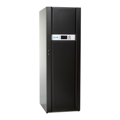
Fideltronik Inigo Lupus Series User manual

500 – 700 – 1000 – 1600VA
User Manual

2
Index
Description................................................................................................3
Operating principle....................................................................................4
Installation & use.......................................................................................4
Panel and backboard of UPS................................................................4
Installation & use steps .........................................................................5
Instructions on Panel Indicating LED & LCD and Buzzer.....................6
Storage & transportation...........................................................................6
Maintenance & repair................................................................................7
Ordinary Problems................................................................................7
Maintenance..........................................................................................7
Replacing the Battery............................................................................8
Safety precautions ....................................................................................9
Technical specifications ..........................................................................10
Terms of warranty ...................................................................................11
List of of service centers.........................................................................12
•Please read this user manual carefully before operation.
•Please keep this manual handy for future reference.
•The printer socket is applicable for laser printer.(No output if mains is down).
•It is prohibited to connect loads such as electric fan, electric drill or electric dryer

3
Description
LUPUS UPS series is a new generation of high-performance safe and
reliable uninterrupted power supply with the characteristics of voltage
stabilizing functions, excellent machine performance, comprehensive
automatic protection functions, small and exquisite appearance design,
visually display, and easy-to-use feature. It can provide the computer and its
peripheral equipment with pure and stable uninterrupted AC power supply.
Main Features
●
Extra-Wide Input Voltage Range
The input voltage range is very wide from 165V to 275V; provided with
voltage stabilizing functions; wide application range.
●Digital Control Technology
Having MCU as its control core, it can automatically monitor the input surge,
decline, break, abnormal frequency, output load status and battery status
etc., thus providing the load with comprehensive protections. Complete in
functions.
●Complete Protection Function
With protections for input over-voltage/under-voltage, surge, output over
voltage, over loading, short circuit, over charged battery and under voltage,
has greatly improved the reliability.
●Battery cold start and under voltage self-starting functions
With the battery start function when there is no electric supply, and the
run-out battery self-starting function when there is renewed electric supply.
These two functions have effectively enhanced the battery functions.
●Intelligent Power Management
Optional monitoring function. The associated software can save data and
shut down computer automatically, as well as proceed real-time monitoring
of the UPS.

4
●
Auto start
UPS is equipped with a switch configuration mode: ON UPS starts
automatically when you connect the power supply in the OFF position
requires manual switching.
Operating principle
LUPUS series UPS (hereafter shortened as UPS) will not supply power from
its battery when the mains is working normally, which means the mains goes
through UPS into the computer with stabilised voltage.
When the mains is down, UPS will switch to Inverter mode. When the mains
voltage is lower than 165Vac or higher than 275Vac, UPS will also switch to
Inverter mode, so as to effectively protect the computer from the interruption
of electricity network.
When the mains resumes to normal status, UPS will start automatically, and
the battery charger will start charging the battery as well.
The battery will be charged fully within 8 to 10 hours of charging.
Installation & use
Panel and backboard of UPS
Figure (1) Panel and backboard schematic diagram of UPS LED models
RS232
RS232
OUT IN
For TEL/DSL/FAX/Modem
DC INPUT
Surge Protection
AC INPUT
LUPUS 500 - 700 - 1000VA LUPUS 500 LUPUS 700 VA - 1000VA
LUPUS 1600VA LUPUS 1600VA
Surge Protection
AC OUTPUT
1. Mains status Indicating Led
2. Power Switch
3. RJ11+RJ45 Protection Port (Protecting Fax, Modem, Network Card etc.)
4. Computer Socket (Inverter Protected Output Socket)
5. Printer Socket (Applicable for Laser Printer, Power<600W)
6. Dry Joint Communication Interface
7. Input Socket with Fuse ( With another Spare Fuse)

5
8. Battery slot
9. Switch startup configuration
Figure (2) LCD Schematic Diagram of UPS LCD models
Installation & use steps
1. After unpacking the UPS, check whether there is any mechanic injury
due to transportation. If the UPS appearance has been serious injured,
further examination is needed.
2. Place the UPS in an well-ventilated dry place; do not block the
ventilation of two UPS sides.
3. The rated input and output of UPS are both 230Vac 50 Hz.
The input is a three-core power cord (P+N+G), the output is a
three-core standard IEC socket, and the UPS case is connected with
ground wire. Please make sure the ground wire is well connected.
4. Plug the UPS input power cord into the mains socket, and plug the other
end into the UPS input socket. Please make sure the neutral wire and
live wire are in accordance with national standards, and the ground wire
should be well connected.
The following is the front schematic diagram of input mains socket:
5. Connect the computer and monitor to the “Computer Sockets” of the
UPS (Output Inverter Protected : AC 230Vac), and connect the printer to
the “Printer Socket” (Output Stabilised only : AC 230Vac).
LN

6
6. For the UPS with RJ11+RJ45 ports, the “IN” socket is for
communication signal input, and the “OUT” is for modem or network
card, so as to have the protection for the communication equipment
ports.
7. To Turn On gently press the UPS power switch for 2 seconds, and
turn on the computer after the UPS starts working.
8. To Turn Off gently press the UPS power switch for 2 seconds to
turn off the UPS.
Instructions on Panel Indicating LED & LCD and Buzzer
UPS Work Status
LCD DISPLAY BUZZER
-Normal Electric Supply
-Electric Supply is connected to the load
-Battery is charging
AC NORMAL“ ”On
OUTPUT“ ” On
The battery indicator is growing
Silent
-Normal Electric Supply
-Electric Supply is connected to the load
-Battery fully charged
AC NORMAL“ ” On
OUTPUT“ ” On
Displays the full battery bar
Silent
-Electric Supply is down or abnormal
-UPS is supplying power from the
Inverter to the load
BATTERY“ ” On
OUTPUT “ ” On
The reduction of lighted battery capacity
indication led means that the battery is
discharging
Slow Beeping
Every 3 Seconds
And beeps every 10
seconds after 10 beeps
-UPS battery is fully discharged
-Please save data and shut down
computer immediately
Only one battery capacity Led is blinking Fast Beeping
Every 1 Second
-UPS output overloaded, please reduce
the load, and plug the large-load
equipment such as printer etc to the
printer socket
OVERLOAD“ ” On
Fast Beeping
Every 1 Second
Storage & transportation
LUPUS UPS is a high-grade and precise power supply, so is well packed
with the designated carton and shock-absorbing foam for storage and
transportation, and MUST be kept from humidity, dust, shake or chemical
erosion.

7
Maintenance & repair
Ordinary Problems
If the UPS is operated with normal method, the panel will display the
current working status. The following are ordinary UPS failure problematics :
Problem 1: The UPS will not switch to electric supply status after turning
on. Solution : Check whether the power cord is well connected with the
electricity network socket; whether the input AC fuse has burned out. (There
is one spare fuse in the input fuse socket, please use fuse of same
specifications).
Problem 2: Unplug the input power cord after it is turned on, but the
UPS cannot switch to Inverter supply status.
Solution : The battery voltage is too low, output is overloaded, or output
short circuit; please charge the battery or change it, check whether the
output is overloaded and reduce the load, or whether the output loop is
short-circuited.
Maintenance
If the UPS is not being used for a long time ,then it should be charged 8~10
hours every three month. If possible, please discharge the battery with the
computer or 100W light bulb for 1~3 minutes. The purpose of discharging is
to activate the battery. The battery is only allowed for long-time storage after
it is fully charged; or the battery capacity will reduce due to performance
erosion after long-time stall. The long-time under voltage (or even zero
voltage) due to battery self-discharging will “kill” the battery.
Regularly check the power supply and input and output lines of all
equipments, so as to guarantee the reliability of peripheral lines.

8
Timely maintain or change the battery according to the following indications :
Surroundings
Temperature
Battery Life Being Examined
Every Six Months
Being Maintained Every
Month
20° 3-5 years Within 18 months Discharge it for 1-3
minutes every month if
30° 1.5-2 years Within 10 months
Replacing the Battery
There is a specially designed floor plate for the easy replacement of
battery. And the battery should be changed preferably after the UPS has
been turned off, and the AC power cord has been unplugged:
1. Turn off the UPS, and unplug all AC input and output power
cords;
2. Unscrew the 7 screws on the cover with a cross screwdriver;
3. Carefully put the UPS upside down, and unscrew the 3 screws
on the battery cover;
4. Carefully take out the battery, and put in new battery (12V, 7AH
maintenance free battery);
5.
Lock the battery cover and top cover.
Replacing the battery in the other models require, after opening the cover,
removing the clamps from the battery and careful of their exits.
Changing the
autostart
functionality
/ manual
In order to change the way you start the UPS, disconnect power from the
mains supply and turn off all button on the front panel. Toggle switch on the
back (ON or OFF) and wait about 1 minute. After restarting the UPS will start
up according to the mode setting.

9
Safety precautions
In order to ensure the safe use of this UPS, please read the the following
instructions, so as to avoid mistake or danger in the use:
1. This product is designed for home computer/commercial personal
computer (PC), and it is not recommended to be used for
life-supporting system or other specific important equipments.
2. It is dangerous to dismantle the UPS while it is on, as it may lead to
an electric shock.
3. The UPS should be placed at least 25 cm from the monitor, so as to
prevent interference.
4. It is absolutely prohibited to place cups or other liquid containers on
the top this machine, so as to avoid internal short circuit that may
lead to dangers such as electric shock etc.
5. Do not store or use this machine in the following surrounds:
•Sites with flammable gas, erosive material or large
amount of dust
•Sites with severe shakes
•Outdoors
6. If the machine has problem, please cut the power supply and
contact local distributor.

10
Technical specifications
UPS model: LUPUS 500 – 700 – 1000 – 1600VA
Input features
Voltage Range 150 –290 VAC
Frequency
Range(Hz) 50Hz ± 10%
Output features
Power 300 – 420 – 600 – 960W
Autonomy >10 min. (1 PC)
Voltage Range 230 VAC ±10% (battery work)
Frequency
Range(Hz)
Synchronizing with input AC while it is
normal ,and 50±0.5% on battery mode
Protection
Reduced voltage Start inverter when the input voltage. <165VAC
Increased voltage Start inverter when the input voltage. > 275VAC
Deep discharge
batteries
UPS off when the battery voltage drops below
the set level,
- Turn on the battery indicator
Overload or shorting Immediately for overloads > 150%
Fast for a compact battery
Switching time < 6ms
Panel Indicators
LCD display Network operation, battery operation, overload,
battery status, battery discharged, failure
Sound alarm Operation with battery, battery discharged,
overload
Weight(kg) 6,3 – 15 – 15 – 20 kg
Size: (W×D× H) mm
320x90x165 (500VA),
380x120x220 (700/1000VA),
460x150x220 (1600VA)
Temperature -5 °C +40°C
Relative humidity 0-90% non condensing

11
Terms of warranty
We provide a warranty for a period of 24 months from the date of sale of the
UPS, but not longer than 36 months from date of manufacture. Disclosed in
this period, defects will be corrected free of charge within no more than 14
working days from the date of delivery to an authorized service center.
Warranty does not cover:
- Damage caused by the use of the product not in conformance
for its intended use and the instruction manual
- Damage caused by improper transportation or improper handling
- Mechanical damage, moisture, liquid spill induced defects and their
- Damage caused by arbitrary, made by the user or other unauthorized
repairs, alterations or design changes
- Activities provided in the manual, to which the user must own and at
their own expense, such as: installation, commissioning, verification
activities, replacement mains fuse.
Proper packaging / protection equipment to the site should be sent to the
sender. It is recommended that the unit was shipped in the original
containers equipped with protective pads fitted to the device. The use of
alternative packaging, provided they adapt to the size and weight of devices
shipped, providing adequate protection against mechanical damage.
In the case of product defect, please contact your dealer or authorized
service center to arrange repair.
Endorsements for warranty repair
No. Date of filing Date of implementation Description of repair Signature of contractor
1
2
Serial number, manufacturing date .............................................................
Date of sale ................................ Seller .....................................................

12
List of of service centers
Fideltronik Inigo Sp. z o.o.
Obroncow 25,
03-933 Warsaw
tel / fax: +48 022 871 43 36
www.fideltronikinigo.com
This manual suits for next models
4
Table of contents
Other Fideltronik Inigo UPS manuals

