Fideltronik Inigo LUPUS 600N User manual


1
SAFETY INSTRUCTION
Thank you for purchasing this power protection product. Please read manual carefully
and remember about all warnings and operating instructions in this manual strictly.
Save this
manual for future use and properly operate installing and using ups unit.
Transportation and preparation for usage
UPS should be shipped only in the original package to protect against shock and impact.
Do not dismantle the UPS system, except the specialized technical personnel.
Do not plug the UPS input into its own output.
Do not attach a power strip or surge suppressor to the UPS.
Do not attach non-computer-related items, such as medical equipment, life-support equipment,
microwave ovens, or vacuum cleaners to UPS.
Condensation may occur if the UPS system is moved directly from cold to warm environment.
The UPS system must be absolutely dry before being installed. Please allow at least two hours
for the UPS system to acclimate the environment.
Do not install the UPS system near water or in moist environments.
Do not install the UPS system where it would be exposed to direct sunlight or near heater.
Do not block ventilation holes in the UPS housing.
Installation
UPS must be installed in a controlled environment (temperature controlled, indoor area free of
conductive contaminants). Avoid installing the UPS in locations where there is standing or
running water, or excessive humidity.
Caution - Changes or modifications not expressly approved by the party responsible for
compliance could void the user's authority to operate the equipment.
Caution - Uninterruptible power systems (UPS) –Part 1: General and safety requirements for
UPS (reference: EN62040-1) / CE (EN60950-1:2006+A11:2009+A1:2010+A12:2011).
Caution - Electromagnetic compatibility (EMC) requirements for UPS (reference: EN62040-2
Category C1) / CE (EN55022:2010; EN55024:2010).
Operation
Prevent no fluids or other foreign objects from inside of the UPS system.
Do not connect any devices which would overload the UPS system to the UPS output sockets.
Place cables in such a way that no one can step on or trip over them.
Do not connect domestic appliances such as hair dryers to UPS output sockets.
The UPS can be operated by any individuals with no previous experience.
UPS must be connected only to an earthed shockproof outlet close to the UPS system.
Please use only VDE-tested, CE-marked mains cable (e.g. the mains cable of your computer) to
connect the UPS system to the building wiring outlet (shockproof outlet).
Maintenance, service and faults
The UPS system operates with hazardous voltages. Repairs may be carried out only by qualified
maintenance personnel.
Caution - risk of electric shock. Even after the unit is disconnected from the mains (building
wiring outlet), components inside the UPS system are still connected to the battery and
electrically live and dangerous.
Storage & Maintenance
The UPS system contains no user-serviceable parts. If the battery service life (3~5 years at 25°C
ambient temperature) has been exceeded, the batteries must be replaced. In this case, please
contact your dealer. Remember VRLA batteries used in ups must be properly recycled !!!
Before storing, charge the UPS 5 hours. Store the UPS covered and upright in a cool, dry
location. During storage, recharge the battery in accordance with the following table:
Storage Temperature
Recharge Frequency
Charging Duration
0 - 40°C
Every 3 months
1-2 hours
2
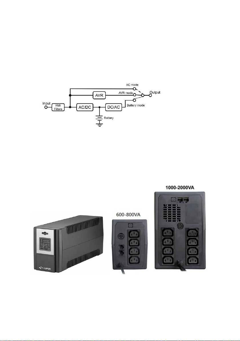
OPERATING PRINCIPLE
LUPUS 600/1000/1500N are standard transformer based UPS build in line-interactive
topology with squared type inverter. UPS is dedicated for protecting computers and other
electronic devices against unpredictable power loss and instability. Basic blocks of device
are: AC Input circuit with overvoltage protection and EMI filters, Battery charger ( AC/DC
conversion), Inverter ( DC/AC conversion ), Battery set, AVR circuit (Automatic output
voltage regulator), Commutation module and AC output block.
When mains power is stable it is transferred to UPS output via AC pass directly. In case too
small or too large mains voltage amplitude AVR circuit modify it and then supply UPS
output. At last in case of power fail inverter starts to power UPS output providing needed
AC power using energy stored in batteries.
View of UPS LUPUS 600N - 1500N
Lupus 600N /1000/1500N with IEC 320 outlets
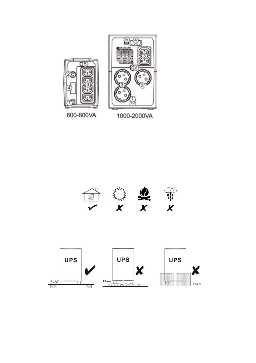
3
Lupus 1000/1500N with mixed IEC 320 & CEE7 FR outlets
1. AC input wire
2. Input AC breaker
3. UPS protected outlets
4. RJ 45 FAX/Modem /LAN protection
5. USB communication port
UPS INSTALLATION DEMANDS
UPS should be placed on flat and clean surface.
Should be protected against: dust, vibrations, humid and chemically aggressive
environment or high temperature.
s
Placing of UPS : UPS during activity may produce heat - don`t cover ventilation slots.
Demanded free space around: at least 100mm from sides and 200mm from back plate
of ups.

4
UPS POWER ON
Ups will turn ON automatically after placing plug into AC wall socket.
For switching OFF UPS main front switch must be pressed ON for 3-4 seconds.
On LCD screen will be shown "UPS OFF".
In order to switch ON ups when is no AC power ("cold start") main front switch must be
pressed for about 2-3 seconds, and for turning OFF in battery mode operation main switch
should be used for about 4 -5 seconds.
SOUND ALARM
During battery mode operation sound alarm appears 2 times every 8 seconds.
After short pressing main switch sound alarm could be blocked or activated again.
LCD DISPLAY view
Lp.
Item
Description
1
Output Load
Presents current ups output load
2
Battery charge level
Presents current battery capacity
3
AC normal
AC power mode
4
Battery mode
No AC at ups input or wrong AC conditions
5
Overload output
Too much load at ups output
6
Battery bad
Replace battery to good one
7
Fault
Critical error of ups hardware problem
8
Input voltage value
Currently measured AC input voltage
9
Output voltage value
Currently measured AC output voltage
* Critical Error and Overload will turn on continuous sound alarm !!!

5
TROUBLE SHOOTTING
Problem
Possible cause
Solution
UPS cannot turn on,
LCD no light
Battery voltage < 10V
Charge batteries
PCB failure
Factory Service
UPS is permanently on
battery mode
Bad AC connection
Connect ups properly to AC source
AC breaker activated
Check load level, switch on breaker
PCB failure
Factory Service
Backup time too short
Batteries not fully charged
Charge batteries for few hours
Batteries poor
Replace batteries; if problem not solved -
Factory Service
Continuous sound alarm
Overload / short output
Reduce load
TECHNICAL SPECIFICATION
Model
600
1000
1500
OUTPUT Power max.
600 VA / 360 W
1000VA/600W
1500 VA / 900 W
Output voltage range
220/230/240 VAC
Input voltage range
-30 % +25%
AVR Function
Yes - 2 "boost" levels & 1 "buck"
Input frequency range
Auto detect 50/60 Hz (+/-10%)
Input protection
Overvoltage, over current
Output voltage stability
+/-10% (Battery operation)
Output frequency stability
50/60 Hz +/- 1Hz (Battery operation)
Output protection
Over current, short protection
Transfer time
Typical 6 ms, 10 ms max.
Output voltage shape
Approximated sinwave (SQUARED)
Nominal DC voltage
12V
24V
24V
Batteries
12 V/7 Ah
12 V/7 Ah x 2
12V/9 Ah x 2
Charge time
4-6 hours to 90% capacity
Dimension (DxWxH) mm
315 x 100 x 141
343 x 135 x 208
343 x 135 x 208
Wight (kgs)
5,2 kg
9,5 kg
11 kg
Humidity
0-90 % RH @ 0-40°C (no condensation)
Noise level
< 40 dB
*Specifications may be changed without further notice.

6
BATTERY EXCHANGE
Typical life time of VRLA batteries is 3 to 5 years.
Temperature above 25°C, frequent deep discharge may make this period even shorter.
WARNING !!!
- Exchange of battery should be done by qualified personnel.
- Batteries Exchange must be done when ups is disconnected from load and
mains source.
- UPS could generate danger voltage even when is disconnected from AC line, always it
must be remembered.
- Batteries should be changed to proper type dedicated to this UPS type.
- Old batteries must be recycled properly according to local regulations.
IT IS HIGH DEMAND TO FOLLOW ALL FORMAL PROCEDURES AND
REGULATION DURING ANY SERVICE ACTIVITY WITH ELECTRICAL DEVICES
SUCH AS UPS AND VRLA LEAD ACID BATTERIES !!!
Main steps during battery replacement:
1. Switch off and disconnect all loads from ups outlets.
2. Turn UPS OFF.
3. Disconnect UPS from AC line.
4. Press down battery cover and push it in direction presented on picture below.
5. After removing cover disconnect batteries and pull out battery set .
Be sure to deliver the spent battery to a recycling
facility or ship it to your dealer in the replacement battery
packing material

7
6. Place new batteries inside, connect wires proper way as it was before and close cover.
7. UPS is ready to operate with new battery set.
SOFTWARE MONITORING
UPS could communicate with computer via USB port using cable A-B type.
Cable is included in UPS set with individual license number KEY for software.
Monitoring software program is called UPSILON 2000.
With user manual is added product KEY and link for download on separate
document.
In case of loosing KEY a new license must be bought !!!
View of Upsilon 2000 license document above. (www.megatec.com.tw).

8
WARRANTY TERMS ( for POLAND area only)
UPS warranty is given for 24 months from date of invoice.
Any failures reviled during this period will be solved without any cost in term no longer
than 14 days from delivery of unit to authorized service point.
Warranty is perform in "door to door" system and is proceeded in central company service.
Delivery is done at Fideltronikinigo cost via authorized express company.
All detailed information's are placed on our web site or could be obtain in direct contact to
company office.
In order to perform proper shipment way in case of need we suggest preserve
original ups package and foams !
Company could not take responsibility if devices sent to service will be mechanically
damaged as a result of poor packing way.
From warranty are excluded such issues:
-damage caused by unit use against terms placed in manual and general purpose;
-damaged caused via wrong shipment or not proper maintenance of unit;
-mechanical damage and any damage via exposition to heat, liquids atc.;
-damages after unauthorized changes in unit construction
-all activities that are explained in user manual as obliged to user : installation,
configuration, testing, basic user maintenance, etc.
In case of any technical problems please contact with dealer or company service.
Company web site : www.fideltronikinigo.pl
This manual suits for next models
2
Table of contents
Other Fideltronik Inigo UPS manuals


Popular UPS manuals by other brands


Staco Energy
Staco Energy FLP-10-POPC-5-R-4Y-2Y user manual

Lowell power
Lowell power UPS9AC-1000 User & installation manual

LEGRAND
LEGRAND KEOR HPE 100 kVA operating manual

iBall
iBall Nirantar UPS 1080V user manual

MGE UPS Systems
MGE UPS Systems Galaxy 3000 Installatie en gebruikershandleiding

CyberPower
CyberPower PR1000ELCDRTXL2U user manual