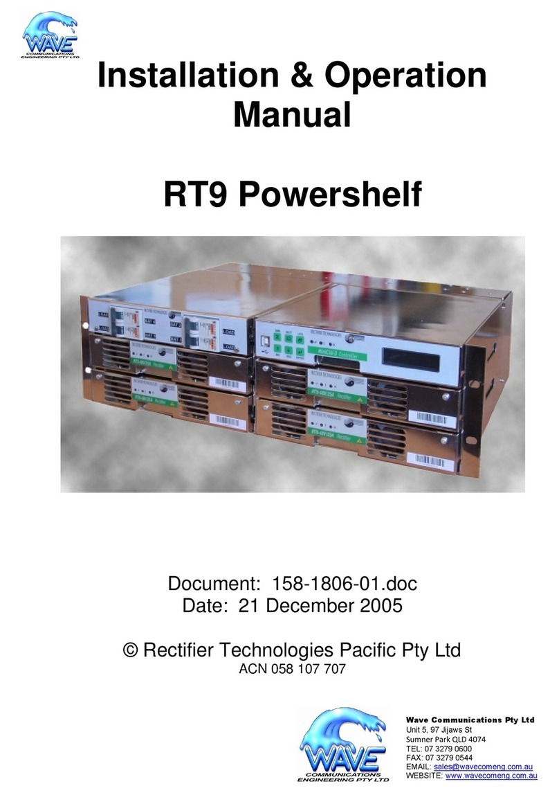
Fideltronik Inigo MY Series User manual

User Manual
MY Series (10kVA-40kVA) UPS


MY Series (10kVA-40kVA) UPS
User Manual
Foreword
i
Foreword
Summaries
Thank you for choosing the Uninterruptible Power System (hereinafter referred to as the "UPS")
product!
This document gives a description of the MY series UPS, including the features, performance,
appearance, structure, working principles, installation, operation and maintenance.etc.
Please save the manual after reading, in order to consult in the future.
The figures in this manual are just for reference, for details please see the actual product.
Suitable Model
MY10/MY10S/MY15/MY15S/MY20/MY20S/MY30/MY30S/MY40/MY40S
Symbol Conventions
The manual quotes the safety symbols, these symbols used to prompt users to comply with safety
matters during installation, operation and maintenance. Safety symbol meaning as follows.
Symbol
Description
Alerts you to a high risk hazard that could, if not avoided, result in
serious injury or death.
Alerts you to a medium or low risk hazard that could, if not
avoided, result in moderate or minor injury.
Alerts you to a potentially hazardous situation that could, if not
avoided, result in equipment damage, data loss, performance
deterioration, or unanticipated results.
Anti-static prompting.

Foreword
MY Series (10kVA-40kVA) UPS
User Manual
ii
Symbol
Description
Be care electric shock prompting.
Provides a tip that may help you solve a problem or save time.
Provides additional information to emphasize or supplement
important points in the main text.
Product standard: Q/ZZKJ 001
Change History
Changes between document issues are cumulative. The latest document issue contains all the changes
made in earlier issues.
Issue 001 (2020-03-02)
First issue.

MY Series (10kVA-40kVA) UPS
User Manual
Contents
iii
Contents
1 Safety Description.........................................................................................................................1
1.1 Safety Announcements.....................................................................................................................................1
1.1.1 Safety Instructions ..................................................................................................................................1
1.1.2 Use Announcements for Battery .............................................................................................................2
1.1.3 Anti-Static Protection..............................................................................................................................3
1.2 Operation and Maintenance Requirements ......................................................................................................3
1.3 Environment Requirements..............................................................................................................................3
2 Overview.........................................................................................................................................5
2.1 Product Intro.....................................................................................................................................................5
2.1.1 Model Meaning.......................................................................................................................................5
2.1.2 Features...................................................................................................................................................6
2.1.3 Appearance..............................................................................................................................................7
2.1.4 Communication.....................................................................................................................................12
2.1.5 Fittings Illustration................................................................................................................................15
2.2 Work Principle................................................................................................................................................15
2.2.1 Work Principle Diagram........................................................................................................................15
2.2.2 Work Mode ...........................................................................................................................................16
3 Installation....................................................................................................................................20
3.1 Announcements..............................................................................................................................................20
3.2 Installation Preparation ..................................................................................................................................20
3.2.1 Tools......................................................................................................................................................20
3.2.2 Install Environment...............................................................................................................................21
3.2.3 Install Space..........................................................................................................................................21
3.2.4 Select Breaker & Wires.........................................................................................................................21

Contents
MY Series (10kVA-40kVA) UPS
User Manual
iv
3.2.5 Select Input Breaker..............................................................................................................................22
3.2.6 Select Wires ..........................................................................................................................................23
3.3 Transport and Unpacking ...............................................................................................................................26
3.3.1 Transport...............................................................................................................................................26
3.3.2 Unpacking.............................................................................................................................................27
3.4 Mechanical Installation ..................................................................................................................................29
3.5 Electrical Connection.....................................................................................................................................32
3.5.1 UPS Wiring Operation ..........................................................................................................................32
3.5.2 Wiring Between UPS and External Battery ..........................................................................................37
3.5.3 Wiring of Parallel System .....................................................................................................................39
4 LCD Screen Operation ...............................................................................................................44
4.1 Menu Hierarchy .............................................................................................................................................44
4.2 Power On for The First Time .........................................................................................................................45
4.3 Main Page ......................................................................................................................................................45
4.4 System Working Status Display.....................................................................................................................46
4.5 Monitoring Page.............................................................................................................................................48
4.6 Setting Management.......................................................................................................................................48
4.6.1 Parameter Setting..................................................................................................................................49
4.6.2 Function Setting....................................................................................................................................50
4.6.3 Log Management ..................................................................................................................................52
4.6.4 Screen Setting .......................................................................................................................................52
4.6.5 Permission Setting ................................................................................................................................53
5 Touch Screen Operation ............................................................................................................55
5.1 Menu Hierarchy .............................................................................................................................................55
5.2 Main Page ......................................................................................................................................................57
5.2.1 Icon Meaning ........................................................................................................................................57
5.2.2 Working Status......................................................................................................................................58
5.2.3 Bypass Information Page ......................................................................................................................60
5.2.4 Mains Informaiton Page........................................................................................................................61
5.2.5 Battery Information Page......................................................................................................................61

MY Series (10kVA-40kVA) UPS
User Manual
Contents
v
5.2.6 Output Information Page.......................................................................................................................62
5.3 Login Page .....................................................................................................................................................63
5.4 Information Management Page ......................................................................................................................63
5.4.1 Run Information Page ...........................................................................................................................64
5.4.2 History Record Page .............................................................................................................................66
5.4.3 User Log Page.......................................................................................................................................66
5.4.4 Device Infomation Page........................................................................................................................67
5.5 Setting Management Page..............................................................................................................................68
5.5.1 System Manage Page ............................................................................................................................68
5.5.2 Battery Management Page ....................................................................................................................71
5.5.3 Battery Test Page ..................................................................................................................................74
5.5.4 Dry Contact Page (Reserved)................................................................................................................75
5.5.5 Communicaiton Setting Page................................................................................................................77
5.5.6 HMI Setting Page..................................................................................................................................77
5.5.7 Password Setting Page ..........................................................................................................................78
5.5.8 Device Configuration Page ...................................................................................................................78
5.5.9 Dedust Setting Page..............................................................................................................................81
5.5.10 Record Manage Page ..........................................................................................................................81
5.6 Current Fault Page..........................................................................................................................................83
5.7 Buzzer Control ...............................................................................................................................................84
5.8 ON\OFF Operation.........................................................................................................................................85
6 Use and Operation ......................................................................................................................87
6.1 Check Before Startup .....................................................................................................................................87
6.2 Startup Operation ...........................................................................................................................................87
6.3 Shutdown Operation.......................................................................................................................................88
6.4 Parallel System Operation..............................................................................................................................88
6.4.1 Start Parallel System.............................................................................................................................88
6.4.2 Shut Down Parallel System...................................................................................................................89
6.4.3 Exit Parallel System Online ..................................................................................................................89
6.4.4 Add New UPS into Parallel System Online ..........................................................................................89

Contents
MY Series (10kVA-40kVA) UPS
User Manual
vi
6.4.5 Redundance Function of Parallel System..............................................................................................90
6.5 Periodic Preventative Maintenance................................................................................................................90
6.6 Battery Maintenance ......................................................................................................................................90
6.7 Troubleshooting..............................................................................................................................................91
6.7.1 Common Fault ......................................................................................................................................91
7 Package, Transportation and Storage......................................................................................96
7.1 Package ..........................................................................................................................................................96
7.2 Transportation ................................................................................................................................................96
7.3 Storage ...........................................................................................................................................................96
A Technical Specifications ...........................................................................................................97
B Acronyms and Abbreviations ................................................................................................100

MY Series (10kVA-40kVA) UPS
User Manual
1 Safety Description
1
1 Safety Description
This chapter introduces the safety announcements. Prior to performing any work on the UPS, please
read the user manual carefully to avoid human injury and device damage by irregular operations.
1.1 Safety Announcements
This section introduces the safety announcements that must be complied with and pay special
attention while installing, using, maintenance and other relative operations.
Before operating, please read the announcements and operation instructions in this section carefully
to avoid accident.
The DANGER, WARNING, CAUTION, etc. in the manual are not all the safety announcements that
you must abide by, they are just the supplements for the safety announcements during operating.
Our Company does not undertake the responsibility caused by violating common safety operation
requirements or the safety standard of design, manufacture and use.
1.1.1 Safety Instructions
There exists high temperature and high voltage inside the UPS. During using, please strictly comply
with all warnings and operation instruments on the UPS and in the user manual.

1 Safety Description
MY Series (10kVA-40kVA) UPS
User Manual
2
The UPS is class C3 device. If it is used in residential purpose, it may cause wireless interference.
User should take actions to avoid the interference.
No liquid or other objects are allowed to enter the UPS.
UPS must be well grounded.
In case of fire, please use dry power fire extinguisher. If using liquid fire extinguisher, it may
cause electric shock.
1.1.2 Use Announcements for Battery
Please use specified battery. Non-specified battery will damage the UPS.
Only authorized professional can replace battery. Do not wear conductive objects, such as
watches, bracelets and rings during operating. Wear rubber shoes and gloves and use tools with
insulated handle.
Don't put tools or other conductive objects on the battery.
It is prohibited to short the positive pole and negative pole of the battery or connect them
reversely, which is to avoid fire or electric shock.
Before connecting or disconnecting the battery terminals, disconnect charger first.
The battery must be with the same type, model and manufacturer.
Battery should be kept away from fire source or other electrical equipments that may easily cause
spark to avoid human injury.
Don't open or destroy the battery. The electrolyte in the battery includes some dangerous objects,
such as strong acid, which will be harmful to skin and eyes. If it is careless to touch the
electrolyte, clean it by a lot of water immediately and then check it in the hospital.
The waste battery should be disposed according to the local regulations.

MY Series (10kVA-40kVA) UPS
User Manual
1 Safety Description
3
1.1.3 Anti-Static Protection
The static generated by human bodies may damage the electrostatic-sensitive components on PCB.
Before touching the sensitive component, please wear anti-static rings and well connect the other end
of the anti-static rings to ground.
1.2 Operation and Maintenance Requirements
Only authorized professionals are allowed to open the UPS chassis, or it may cause electric shock
and the caused UPS fault is out of the guarantee range.
If UPS needs to be moved, rewired or maintained, disconnect all electrical connection, such as
AC power, battery power, etc. to isolate power input. Do not do any work on the UPS until it is
powered off completely (≥10min). Otherwise, the output may exist electricity, which may cause
electric shock.
When dismantling fan, do not put fingers or tools into the rotating fan to avoid device damage or
human injury.
1.3 Environment Requirements
Do not put the UPS in the environment where has inflammable, explosive gas or smog, do not do any
operation in this environment.
Do not use the UPS in the place where has direct sunshine, rain or wet.
The normal work temperature of UPS is -5℃~40℃, relative humidity: 0%-95%, with no
condensation (recommended work temperature is 20℃~25℃, humidity is about 50%).

1 Safety Description
MY Series (10kVA-40kVA) UPS
User Manual
4
Put the UPS in the flat floor without vibration and the vertical gradient is less than 5°. Keep
good ventilation around the UPS. The clearance between the rear or the side of UPS and adjacent
devices or wall should be at least 300mm~500mm. Poor ventilation will rise temperature inside
UPS, which will reduce the service life of inner components and even affect the life span of the
UPS.
The UPS must be used below 2000m. If the altitude exceeds 2000m, it needs to decrease the
rated power according to IEC62040-3:2011 to use.

MY Series (10kVA-40kVA) UPS
User Manual
2 Overview
5
2 Overview
This chapter mainly introduces the UPS's model meaning, features, structure, work principle, etc.
2.1 Product Intro
MY series UPS is whole high frequency, pure online, double-conversion, smart product. The system
is perfect power security for file server, enterprise server, center server, micro-computer, concentrator,
telecom system, data center and others that require high quality power protection. They are widely
used in many key business areas, such as post, finance, network, stock, railway, etc.
2.1.1 Model Meaning
MY □□□
MY series online UPS
Rated power
When it is 10, that means the output power of the UPS is 10kVA;
When it is 15, that means the output power of the UPS is 15kVA;
And so on.
None: Without battery
S: Inner battery
Figure2-1 Model meaning
10/10S/15/15S/20/20S can set three-phase input three-phase output mode, three-phase input
single-phase output mode and single-phase input single-phase output mode. 30/30S/40/40S can set
three-phase input three-phase output mode and three-phase input single-phase output mode.
Three-phase input three-phase output (three in three out) is 33 mode UPS, three-phase input
single-phase output (three in one out) is 31 mode UPS, single-phase input single-phase output (three in
one out) is 31 mode UPS.
Different mode to achieve change can through the wiring, copper bar of fittings and mode connector
(according to 3.5 Electrical Connection).

2 Overview
MY Series (10kVA-40kVA) UPS
User Manual
6
2.1.2 Features
Completely digitalized smart control
The UPS support various input and output mode, such as 33/31 and 11 (just for 10-20k) mode UPS,.
The UPS can monitor the grid frequency (50Hz/60Hz) and self-adapt the frequency. The output
voltage can be set to 220V/230V/240V, which makes the use more flexible.
Energy conservation and high efficiency
Adopts three-level inverter technology and PFC control technology, the output voltage wave is
perfect and the whole efficiency can be 96%, the input power factor is greater than 0.99, which
greatly improves the use ratio of electric energy and reduces the load of power grid.
Smart fan speed control
The fan speed is adjusted automatically in accordance with the load status, which prolong fan life and
reduce noise.
ECO energy conservation mode design
The UPS is designed with ECO energy conservation mode. When the grid is good, if the UPS
operating in this mode, the bypass prior to output, and the efficiency can be 99%.When the bypass
voltage or frequency out of normal range and cannot satisfy the user’s power supply requirement, it
will switch to inverter output, which guarantee the reliability of power supply and also, save energy.
Low mains input voltage
Adopt the independent rapid detection technology. When output load is small, even the battery
voltage is 80V, which is the mains low limit, the battery still doesn't discharge. Therefore, in the
mains mode, all output power gets from the grid, which is to ensure the battery in 100% energy
storage status, and at the same time, reduce the battery discharge times and prolong the service life.

MY Series (10kVA-40kVA) UPS
User Manual
2 Overview
7
2.1.3 Appearance
Figure2-2 Appearance of 10/10S/15/15S/20/20S
Figure2-3 Appearance of 30/30S/40/40S
MY series (10kVA-40kVA) UPS has 2 types of operation panel, LCD screen (as shown in Figure2-4)
and touch screen (optional, as shown in Figure2-5), The UPS appearance and other configuration is
the same except operation panel. Figure2-2 and Figure2-3 just for an example, the actual displayed
should be base on the actual product.
Operation panel
LCD screen

2 Overview
MY Series (10kVA-40kVA) UPS
User Manual
8
Figure2-4 Operation panel
Table2-1 Illustration for LCD screen operation panel
No.
Name
Illustration
Illustration for operation panel
○
1
LCD screen display
Shows the working status and system setting.
○
2
" " page down button
and power off LED
indicator
Short press " " button for 2s, the LCD will enter next setting
page.
○
3
" " function button and
breathing light
Short press " " button to confirm the command of the
current LCD page.
Long press " " button for 3s, will entry the parameter
and function setting page.
When UPS is on, " " button will be in a cycle of light up
to fade out.
○
4
" " page up button and
power on LED indicator
Short press " " button for 2s, the LCD will enter previous
page or previous option.
○
5
"Batt. start" button
Press "Batt. start" button for 7s, the system will build the aux
power.
Combination buttons operation instructions
○
6
Power on
Press the " " and " " button for 2s at the same time, the
UPS on and the corresponding indicate LED is on.

MY Series (10kVA-40kVA) UPS
User Manual
2 Overview
9
No.
Name
Illustration
○
7
Power off
Press the " " and " " button for 2s at the same time, the
UPS off and the corresponding indicate LED is on.
Touch screen
Figure2-5 Operation panel
Table2-2 Illustration for touch screen operation panel
No.
Name
Illustration
Illustration for operation panel
○
1
Touch screen display
Shows the working status and system setting.
○
2
AC/DC indicator
On (green): rectifier works normally;
On (red): rectifier abnormal.
○
3
DC/AC indicator
On (green): inverter works normally;
On (red): inverter abnormal.
○
4
BYP. indicator
On (green): bypass output;
On (red): bypass abnormal.
○
5
BATT. LOW indicator
On (red): battery is low-voltage.
○
6
OVERLOAD indicator
On (red): output is overload or overload protection.

2 Overview
MY Series (10kVA-40kVA) UPS
User Manual
10
No.
Name
Illustration
Buttons operation instructions
○
7
"Batt. start" button
Press "Batt. start" button for 7s, the system will build the aux
power.
○
8
"ON" combination button
Press a couple "ON" buttons for 1s at the same time, the
system will power on.
○
9
"OFF" combination button
Press a couple "OFF" buttons for 1s at the same time, the
system will power off.
○
10
EPO emergency power off
button
Press the button, the system will power outage immediately.
Battery start
The "Batt. start" operation: press "Batt. start" and power on combination button (LCD) or "on"
combination button (touch screen) for 7s at the same time to start up the UPS.
Batt. Start only works in this case: the UPS power on through battery power when there is no mains
power.
Rear panel
Figure2-6 Structure of 10/10S/20/20S rear panel

MY Series (10kVA-40kVA) UPS
User Manual
2 Overview
11
Figure2-7 Structure of 30/30S rear panel
Figure2-8 Structure of 40/40S rear panel
The wiring terminal of 33 mode, 31 mode and 11 mode have a little different. For the detail of the wiring
terminal of each mode please see 3.5.1 UPS Wiring Operation

2 Overview
MY Series (10kVA-40kVA) UPS
User Manual
12
The gate controlled switch release automatically when the maintenance breaker cover is removed and
closes automatically when the cover is locked back.
2.1.4 Communication
The supported communication method of this series UPS include RS485, communication dry contact,
RS232+Dry contact card, RS485+Dry contact card, communication protocol transition card and
SNMP.
Table2-3 Communication method correspondence with hardware port
Communication way
Communication port
RS485
RS485
Dry contact
Dry contact 1: output dry contact;
Dry contact 2: input dry contact (EPO+IN.1)
RS232+Dry contact card
Slot 1 (optional)
RS485+ Dry contact card
Slot 1 (optional)
Communication protocol transition card
Slot 1 (optional)
SNMP
Slot 1 (optional)
RS485
The UPS adopt RS485 series port to communicate with PC. The corresponding pin relationship of
RS485 port between UPS and PC is as shown Table2-4.
Table2-4 The corresponding pin relationship of RS485 port between of UPS and PC
RS485 port of UPS
RS485 port of PC
A (+)
A (+)
B (-)
B (-)
This manual suits for next models
10
Table of contents
Other Fideltronik Inigo UPS manuals
