Fieldpiece VP67EU User manual

Fieldpiece®
Vacuum Pump
with RunQuick™
Oil Change System
OPERATOR'S MANUAL
Models VP67EU, VP67UK, VP67AU,
VP87EU, VP87UK230, VP87AU,
VPX7EU, VPX7UK230, VPX7AU

32
Contents
Important Notice . . . . . . 4
Warnings . . . . . . . . . 4
What’s Included. . . . . . . 5
Certifications . . . . . . . 5
Description . . . . . . . . 6
Features
Specifications . . . . . . . 8
Safety Information. . . . . . 9
General
Environmental
Personal Protection
Vacuum Pump Protection
Setup
Grounding Instructions
Tech Tips . . . . . . . . .14
General
Cold Weather Starts
Setup
Operation. . . . . . . . . 16
RunQuick™ Oil Change System
Evacuation with a 4 Port Manifold
Evacuation with a 3 Port Manifold
Direct Evacuation
Oil Change Procedure
Dynamic Vacuum Measurement
Remote Exhaust
Gas Ballast Valve Switch
LED Indicators
Maintenance. . . . . . . . 30
General
Storage
Vacuum Isolation Test
Oil Window Cleaning
Troubleshooting . . . . . . 32
Limited Warranty . . . . . . 34
Obtaining Service

54
Important Notice
This is not a consumer machine. Only qualified
personnel trained in service and installation of
A/C and/or refrigeration equipment shall use this
vacuum pump.
This vacuum pump is used for evacuating
(drying) refrigerant lines. Fieldpiece model MR45
is available for recovering refrigerant.
Read and understand this operator’s manual
in its entirety before using to prevent injury or
damage to you or equipment.
What’s Included
• VP67/VP87/VPX7 Vacuum Pump
• IEC Power Cord
• (2) 8 Ounce Vacuum Pump Oil
• Operator’s Manual
• 1 Year Warranty
Certifications
WEEE
Do not dispose through
typical waste streams.
UL 1450, CSA 68
UL 121201, CSA 213
CE (VP67/VP87/VPX7)
UKCA (UK models)
!
WARNINGS
Ensure proper equipment grounding, electrical shock risk.
(VP67) Ensure SOURCE VOLTAGE switch matches power source.
Do not expose to rain, electrical shock risk. Store indoors.
Do not connect or disconnect when energized, explosion risk.
Do not use to pump liquid refrigerant, explosion risk.
Do not use to pump flammable media, explosion risk.
Inhalation of high concentrations of refrigerant vapor can block
oxygen to the brain causing injury or death.
Exposure to refrigerant can cause frostbite.
Oil from the vacuum pump can be hot. Handle with caution.
This machine should only be used for evacuation of refrigerant
systems after refrigerant has been removed from the system and
the system has been opened to atmosphere. This machine is not
to be used as a transfer pump for liquids or any other media;
doing so can damage the product.

76
Features
• 10CFM (VPX7), 8CFM (VP87), 6CFM (VP67)
• A2L Ready Safety Certified
• RunQuick™ Oil Change System
- Easy View Window and Oil Backlight
- Change Oil Quickly, Even with the Pump Running
- Extra Oil Bottle Storage
- Elevated Oil Drain Ball Valve
- Wide Mouth Fill Port
- Oil Bottle Cap Storage
- Precision Oil Circulator
• 4 Inline Ports
(1) 1/4”
(2) 3/8”
(1) 1/2”
• Two Stage Pump
• Gas Ballast Switch
• Oil Window LED Indicators
• Remote Exhaust Port
• Quiet Fan-Cooled Operation
• DC Motor (VPX7,VP87)
• Source Voltage Select Switch (VP67)
• Cord Storage Integrated into Rubber Handle
• IEC Power Cord and Lock
• EPO Coated Aluminum Pump (VPX7)
- Super Lightweight
- Enhanced Durability
Description
Performing a proper system evacuation prior
to charging directly increases the expected life
and efficiency of the system. Fieldpiece vacuum
pumps provide a new view at system evacuation.
Good oil is the lifeblood of every evacuation.
You need to know the condition of the oil. You
need to change the oil easily with no mess.
Clearly view the oil condition through the huge
oil tank window.The oil backlight helps to see the
condition of the oil and if the fill level is correct.
With the RunQuick™ oil change system, you
can replace the oil in under 20 seconds without
losing vacuum, even while the pump is running.
The extra wide base helps prevent tipping and
spilling oil. Four inline ports in three different
sizes give you tidy hose routing and hose options.
Place the power cord on the handle for tangle
free storage. Carry the machine to and from the
job site easily and well protected.

98
Specifications
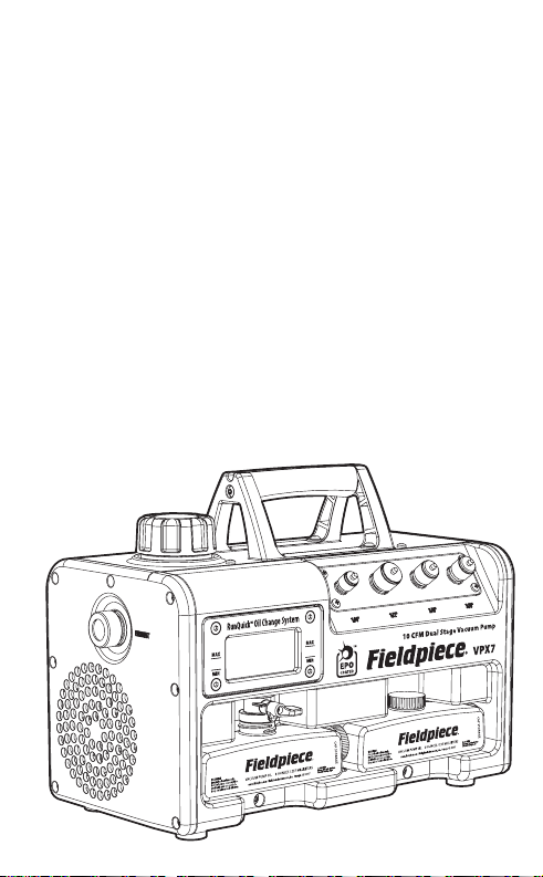
Flow Rate: 10CFM (VPX7), 8CFM (VP87), 6CFM (VP67)
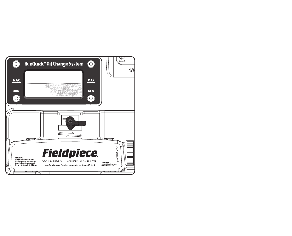
Oil Capacity: 8oz (237mL)
Oil Compatibility: Fieldpiece Vacuum Pump Oil
(Highly refined and optimized for proper sealing and lubrication)
Fieldpiece part numbers: OIL8X3, OIL32, OIL128
Oil Backlight: Blue LED
Oil Drain: Ball valve
Port Sizes: (1) 1/4”, (2) 3/8”, (1) 1/2”
Compressor: Rotary vane, two stage
Motor: 3/4 HP Brushless DC (VPX7/VP87), 1/2 HP AC (VP67)
RPM: 2500 (VPX7/VP87), 3440 (VP67 @ 60 Hz), 2866 (VP67 @ 50 Hz)
Power Source:
120/230 VAC selectable @ 50/60 Hz 1 phase
(VP67UK, VP67EU, VP67AU),
230 VAC @ 50/60 Hz 1 phase
(VPX7EU, VPX7AU, VPX7UK230, VP87EU, VP87AU, VP87UK230)
Nominal Current Draw:
2 AAC (VPX7EU, VPX7AU, VPX7UK230, VP87EU, VP87AU,
VP87UK230, VP67 @ 230V), 5 AAC (VP67 @120V)
Nominal Power:
560 W (VPX7EU, VPX7AU, VPX7UK230, VP87EU, VP87AU,
VP87UK230), 400 W (VP67)
Ultimate Vacuum at Input Ports: 15 microns
Dimensions: 7.9 inch x 11.7 inch x 16.0 inch
(201 mm x 296 mm x 406 mm)
Weight Empty: 24 lb / 10.9 kg (VPX7), 27 lb / 12.3 kg (VP87),
29 lb / 13.2 kg (VP67)
Operating Environment:
30°F to 122°F (-1.1°C to 50°C) (VPX7/VP87),
30°F to 104°F (-1.1°C to 40°C) (VP67)
Hazardous Location: Class I, Division 2, Group D, T4
US Patent: www.fieldpiece.com/patents
Safety Information
General
1. This machine is only intended for use by qualified personnel
trained in servicing and installation of A/C/Refrigeration
equipment.
2. Read and understand this operator’s manual in its entirety before
using to prevent injury or damage to you or equipment.
3. Always dispose of oil according to local jurisdiction.
Environmental
1. Use only within operating environment specification.
2. Ensure fan opening is clear of debris.
3. Explosion and fire risks:
Do not use near sewer lines.
Do not use in poorly ventilated enclosed areas.
Do not use near gasoline, acetylene, or other flammable gases.
Do not use to pump hydrocarbons.
Do not use near flames or sparks.
Assume all components are pressurized.
Personal Protection
1. Frostbite danger. Be careful using hoses.
2. Use personal protective equipment:
Wear safety goggles.
Wear earplugs if using for long durations.
Wear protective gloves.
3. Oil from the vacuum pump can be hot.
Use caution while handling.
4. Do not use in poorly ventilated enclosed areas.

1110
Safety First!
For use only by qualified and certified technicians in the safe use,
handling, and transporting of refrigerants. Please refer to flammable
refrigerant safety guides, regional codes and legislation for more
information.
WARNINGS – failure to heed these hazards and actions
can result in serious injury or death
1. Always use a grounded outlet
2. Always wear Proper Protective Equipment (PPE), which includes
gloves and safety glasses
3. Know proper safety and handling requirements of the refrigerant
in the Safety Data Sheet (SDS)
4. Avoid breathing refrigerant and oil vapors
5. Handle hoses and equipment carefully as refrigerant is under
high pressure and can cause frost bite
6. Do not operate in or near explosive atmospheres
7. Perform leak detection in accordance with recommended
practice to verify working environment is free from leaking
refrigerant as it can be toxic and or flammable
8. Only work in well-ventilated areas (minimum of 4 air exchanges
per hour)
9. Ensure power and extension cords are in good working condition
to prevent shock and spark hazards
Additional safety instructions for recovering A2L
refrigerants (e.g. R-32, R-1234yf, R-1234ze):
1. Adhere to local occupational safety codes and possess detailed
knowledge and skills when handling mildly flammable
refrigerants
2. Have emergency, evacuation, and fire protection plans
3. Designate and monitor a Temporary Flammable Zone with a
3-meter perimeter
4. Identify and disable all possible ignition sources within this Zone
5. Monitor air with a flammable refrigerant leak detector within
this Zone
6. Use a ventilation fan to maintain 5 air exchanges per hour within
this Zone
7. Make power connection of the recovery machine and other
equipment outside of the Temporary Hazard Zone
8. Bond the recovery machine outlet port to the recovery tank’s
unpainted fitting with a grounding strap to dissipate static
electricity buildup during recovery process
9. Ensure area around machine is free of debris that could enter air
vents and fan and cause accidental sparking
10. Always remain in attendance and observant when the machine
is running
11. Do not mix flammable refrigerants with air
12. Use an evacuated DOT recovery tank
13. If system has a suspected leak, stop recovery at 0 psig/bar to
prevent air from entering the recovery tank
14. After recovery, purge system with 100% nitrogen before opening
system for repair
CAUTIONS – failure to heed these conditions can cause
equipment damage.
1. Ensure that recovery machine, hoses, tank and other equipment
are in good working condition
2. Avoid overfilling recovery tanks by following refrigerant
manufacturer’s filling instructions and using a weight scale
3. Avoid cross contamination by not mixing refrigerants
!
!

1312
Vacuum Pump Protection
1. Ensure clean oil is added to a level between MIN and MAX lines.
2. Do not use to remove refrigerant from a system. Use a recovery
machine and filter to remove refrigerant and particles from the
system before usingVPX7/VP87/VP67 to evacuate the system.
3. Do not use on pressurized systems. Doing so may damage or
contaminate your vacuum pump.
4. Do not use on ammonia or salt water systems. Doing so may
damage or contaminate your vacuum pump.
5. Store with ports capped to prevent dust from entering.
6. Drain oil after every job and store VPX7/VP87/VP67 empty to
prevent spillage and reduced oil life.
7. (VP67) Ensure voltage select switch matches power source.
Setup
1. Inspect the machine and repair any damaged parts before using.
2. Ensure motor power is switched OFF (left) before connecting or
disconnecting power.
3. Ensure power cord is not damaged.
4. Ensure all equipment is grounded.
5. Extension cord options:
14 AWG or thicker, up to 50 feet (15 m)
DO NOT USE 18 AWG!
NOTICE: Risk of Property Damage.The use of an undersized
extension cord will cause voltage to drop resulting in power loss
to the motor and overheating.
6. Ensure extension cord is grounded, 3 conductor, and is not
damaged.
7. (VP67) Ensure SOURCEVOLTAGE switch matches power source.
Grounding Instructions
This product must be grounded. In the event of an electrical short
circuit, grounding reduces the risk of electric shock by providing an
escape wire for the electric current. This product is equipped with a
cord having a grounding wire with an appropriate grounding plug.
The plug must be plugged into an outlet that is properly installed and
grounded in accordance with all local codes and ordinances.
WARNING – Improper installation of the grounding plug is able to
result in a risk of electric shock. When repair or replacement of the cord
or plug is required, do not connect the grounding wire to either flat
blade terminal.The wire with insulation having an outer surface that is
green with or without yellow stripes is the grounding wire.
Check with a qualified electrician or serviceman when the
grounding instructions are not completely understood, or when in
doubt as to whether the product is properly grounded. Do not modify
the plug provided; if it does not fit the outlet, have the proper outlet
installed by a qualified electrician.

1514
Tech Tips
General
1. Vacuum pumps are not refrigerant recovery machines and should
not be used for recovering refrigerant.
2. Purge the A/C system with a few psi of dry nitrogen before
evacuation to pre-dry the system.This extra step actually saves
time overall because it quickly removes a great amount of
moisture, oil, and other contaminants before you even connect
your pump.
3. Performing a triple evacuation is a great way to ensure a system
is dry. The nitrogen flow can help carry moisture with it out of the
system. A triple evacuation is as follows:
1. Purge with nitrogen
2. Evacuate down to 2000 microns
3. Purge with nitrogen
4. Evacuate down to 1000 microns
5. Purge with nitrogen
6. Evacuate down to below 500 microns
Cold Weather Starts
1. Open an unused input port to ambient for a few seconds until the
pump is running.
2. Warm the pump in your truck/home by letting it sit in a warm
environment.You can warm the oil in your truck/home before
adding it to the pump.
Setup
1. Always use fresh Fieldpiece vacuum pump oil. If oil is left in the
pump for more than a week, the oil may have absorbed enough
moisture from ambient air to affect performance.
2. Refrigerant manifolds can be convenient to charge the system
after evacuation, but their hoses and valves can limit or slow
evacuation. It’s best to use vacuum rated hoses, directly
connected to core removal tools at the service ports.
3. If you want to use a manifold, it’s best to use a 4 port manifold. 4
port manifolds typically have a larger bore to increase flow. They
also isolate the pump from the system and micron gauge without
the need of a shut-off valve on the hose.
4. Hoses:
Short as possible.
Widest diameter as possible.
Vacuum rated.
Core depressors removed.
Ball valve shut-offs instead of low loss fittings.
Good seals.
Replace if worn.
5. Use a vacuum rated Schrader valve core removal tool to
temporarily remove valve cores from service ports.
6. Connect multiple hoses to the inline ports on VPX7/VP87/VP67 to
further decrease hose restriction and increase air flow.

Source Voltage Switch
(VP67) on Back
Power Cord Storage Wrap
4 Input Ports
Extra Oil Bottle Storage
Remote Exhaust Cap
Gas Ballast Valve (Open)
Motor Power Switch (OFF)
IEC Power Cord Inlet and Lock
Power Cord Storage
Oil Tank Cap
Oil Drain Valve (CLOSED)
Backlit Oil Window and Tank Access (4 Screws)
1716
Operation

1918
RunQuick™ Oil Change System
The only way to create a deep vacuum is to
evacuate with fresh oil, especially at the end of
the job. The RunQuick oil change system makes
this old chore a breeze.
Easy View Window and Oil Backlight
There are a few signs that remind you to change your oil.The visual
condition is one of them. If it looks old, change it. You will see tiny air
bubbles with fresh oil. Saturated oil will look more opaque.
Elevated Oil Drain Ball Valve
By elevating the oil reservoir and utilizing a fast opening ball valve,
we made it easy to drain old oil into the empty bottle without a drop
spilled.
Oil Bottle Cap Storage
When you open a fresh bottle of oil, put the cap on the side of the
bottle so you can cap the bottle after you drain old oil into it.
Wide Mouth Fill Port
It is easy to hit your target with the wide mouth fill port.
Change Oil Quickly with the Pump Running
Towards the end of the evacuation is when you need fresh oil the
most.The RunQuick system maintains a vacuum for about 30 seconds
after you drain the oil so you can drain and pump without any loss of
vacuum.
Precision Oil Circulator and Fan
Instead of submerging the pump in excess oil, a small oil pump
constantly lubricates targeted sealing zones.The quiet high speed fan
cools the heat sinks of the motor and pump.
Spare Oil Bottle Storage
Take an extra bottle to and from the job site so you always have that
fresh oil performance bump at the end of the job.

Vapor
Schrader Valve Core
Removal Tools (optional)
4 Port
Manifold
with
Micron
Gauge
Liquid
2120
Evacuation with a 4 Port Manifold
This is the most common evacuation method.
Read the tech tips (page12) for optimum gauge
placement and variations to reduce recovery
times.
1. Always fill with fresh Fieldpiece Vacuum Pump Oil (page 24).
Running the pump without oil will damage the pump and void the
warranty. Oil can be drained while the pump is running if refilled
within 3 minutes (within 30 seconds to maintain your vacuum).
2. Ensure the motor power switch is turned OFF (left).
3. Plug into a matching power outlet (oil backlight should illuminate).
4. Ensure the gas ballast is closed (vertical) (page 26).
5. Connect to the empty, depressurized A/C system.
6. Turn the motor power switch to ON (right).
7. Open line set (hoses, manifolds, removal tools, etc.) to expose the
pump to the system.
To reduce oil contamination early in the job, open the gas ballast until
the sound of the pump quiets down (about 3000 microns). The yellow
LED in the oil window shines if the ballast is open.
8. After the appropriate vacuum is reached, isolate the system from
the pump. You can check the system for potential leaks at this time
by monitoring your micron gauge.
Your vacuum pump has a unique oil suck back prevention feature
to keep your hoses clear of oil. Still, it’s good practice to release the
vacuum at the input port before turning off the pump.
9. Turn the motor power switch to OFF (left), remove your hoses, and
cap the ports to keep components free of contaminants.
10. Disconnect from the system and unplug from power at the outlet.
11. Drain the contaminated oil while the oil is still warm to keep the
pump as clean as possible when stored.

Vapor
Schrader Valve Core
Removal Tools (optional)
3 Port
Manifold
with
Micron
Gauge
Hose with
Shut-off Valve
Liquid
2322
Evacuation with a 3 Port Manifold
This is a common, but less than ideal evacuation
method. Read the tech tips (page 12) for optimum
gauge placement and variations to reduce
recovery times.
1. Always fill with fresh Fieldpiece Vacuum Pump Oil (page 24).
Running the pump without oil will damage the pump and void the
warranty. Oil can be drained while the pump is running if refilled
within 3 minutes (within 30 seconds to maintain your vacuum).
2. Ensure the motor power switch is turned OFF (left).
3. Plug into a matching power outlet (oil backlight should illuminate).
4. Ensure the gas ballast is closed (vertical) (page 26).
5. Connect to the empty, depressurized A/C system.
6. Turn the motor power switch to ON (right).
7. Open line set (hoses, manifolds, removal tools, etc.) to expose the
pump to the system.
To reduce oil contamination early in the job, open the gas ballast until
the sound of the pump quiets down (about 3000 microns). The yellow
LED in the oil window shines if the ballast is open.
8. After the appropriate vacuum is reached, isolate the system from
the pump. You can check the system for potential leaks at this time
by monitoring your micron gauge.
Your vacuum pump has a unique oil suck back prevention feature
to keep your hoses clear of oil. Still, it’s good practice to release the
vacuum at the input port before turning off the pump.
9. Turn the motor power switch to OFF (left), remove your hoses, and
cap the ports to keep components free of contaminants.
10. Disconnect from the system and unplug from power at the outlet.
11. Drain the contaminated oil while the oil is still warm to keep the
pump as clean as possible when stored.

Vapor
Schrader Valve Core
Removal Tools
Micron
Gauge
Liquid
2524
Direct Evacuation
This is usually the fastest evacuation method.
Read the tech tips (page 12) for optimum gauge
placement and variations to reduce recovery
times.
1. Always fill with fresh Fieldpiece Vacuum Pump Oil (page 24).
Running the pump without oil will damage the pump and void the
warranty. Oil can be drained while the pump is running if refilled
within 3 minutes (within 30 seconds to maintain your vacuum).
2. Ensure the motor power switch is turned OFF (left).
3. Plug into a matching power outlet (oil backlight should illuminate).
4. Ensure the gas ballast is closed (vertical) (page 26).
5. Connect to the empty, depressurized A/C system.
6. Turn the motor power switch to ON (right).
7. Open line set (hoses, manifolds, removal tools, etc.) to expose the
pump to the system.
To reduce oil contamination early in the job, open the gas ballast until
the sound of the pump quiets down (about 3000 microns). The yellow
LED in the oil window shines if the ballast is open.
8. After the appropriate vacuum is reached, isolate the system from
the pump. You can check the system for potential leaks at this time
by monitoring your micron gauge.
Your vacuum pump has a unique oil suck back prevention feature
to keep your hoses clear of oil. Still, it’s good practice to release the
vacuum at the input port before turning off the pump.
9. Turn the motor power switch to OFF (left), remove your hoses, and
cap the ports to keep components free of contaminants.
10. Disconnect from the system and unplug from power at the outlet.
11. Drain the contaminated oil while the oil is still warm to keep the
pump as clean as possible when stored.

2726
Oil Change Procedure
Changing oil is easy and visible. Start each job
with fresh oil. Change as needed during the job.
DRAINING OLD OIL
1. For extended pump life, drain the oil immediatly after the job
instead of waiting until the beginning of the next job.
2. Ensure the pump oil inside is warm enough, >75°F (>24°C), for
proper drainage. Run the pump for 10 minutes if ambient temp is
low.
3. Ensure the motor power switch is turned OFF (right).
Running the pump for longer than 3 minutes without oil will damage
the pump and void the warranty.
4. Plug into power to activate the oil backlight.
5. Ensure your old empty oil bottle is located under the oil drain.
6. Open the oil drain valve clockwise (vertical) to empty the oil
reservoir of old oil.
7. Close the valve counter clockwise (horizontal).
8. Remove and cap the old oil for disposal.
ADDING FRESH OIL
9. Ensure the drain valve is closed (horizontal).
10. Unscrew the pump’s oil fill cap 1/4 turn counter clockwise.
11. Open a new 8 ounce bottle of FieldpieceVacuum Pump Oil (OIL8X3).
Put the bottle cap on the side of the bottle (CAP STORAGE).
12. Pour the entire 8 ounce bottle of fresh oil into the oil port and
ensure the oil level is between the MIN and MAX lines indicated on
the window bezel. Replace oil fill cap.
13. Place the empty bottle under the drain valve so it’s ready to gather
used oil during the next oil change.
14. Your vacuum pump is now ready to operate.
Dynamic Vacuum Measurement
During the pull down, the system’s vacuum
level drops faster at the front of the system, near
the vacuum pump.
To ensure that your full system achieves the
target micron level, place the vacuum gauge
as far to the back of the system, away from the
pump, as possible.
Remote Exhaust
Unscrew the brass EXHAUST cap and connect
an obstruction-free garden hose if you need
to exhaust oil mist and vapor remotely to the
outside of a building structure.

2928
Gas Ballast Valve Switch
Much of the air and moisture in a system are
removed before reaching 3000 microns. For wet
systems, you should open the gas ballast during
this initial pull down. Doing so helps the pump
run smoothly and keeps the oil in good condition
for when you need it most -- towards the end of
the evacuation.
At about 3000 microns, when the sound of the
pump quiets down, the gas ballast should be
closed so that a deep vacuum can be generated.
Open
• Set here for initial pumping down
(above 3000 microns) of wet
systems.
• Yellow window LED shines.
• Discharge stroke exposed to
ambient.
Closed
• Normal operating position.
• Yellow window LED off.
• Discharge stroke isolated from
ambient.
LED Indicators
Three columns of LEDs in the oil window
indicate various states. The blue lights of the
right column indicate power is connected. The
blue lights of the middle column shine when the
pump is switched on.The LEDs of the left column
typically indicate the gas ballast valve is open.
Special Messages
Yellow Blink (Solid yellow LED on VP67):
Gas ballast valve open.
Yellow Blink + Red Blink (VPX7/VP87):
Low voltage detected.
Red Blink (VPX7/VP87):
High voltage detected.
Red Solid (VPX7/VP87):
Internal fault detected.
SPECIAL
MESSAGE
(Y/R)
SWITCHED
ON
(2 BLUE)
PLUGGED
IN
(2 BLUE)

3130
Maintenance
General
Wipe with damp cloth to clean the exterior.
Do not use solvents.
Storage
Empty or replace oil at the end of every job.
Don’t leave old oil in the machine. Store the pump
and oil in dry clean areas for longest life.
Oil can lose its sealing properties if left
uncovered. Keep oil sealed until it’s ready for use.
Vacuum Isolation Test
Perform this test to ensure your vacuum pump
and your micron gauge are working properly.
1. Connect your vacuum gauge directly to a port on your pump.
2. Seal the 3 other ports.
3. Ensure the gas ballast is closed (page 26).
4. Switch your pump ON to create a vacuum at your gauge.
If your gauge measures below 200 microns within 1 minute, you
know your vacuum pump and micron gauge are working correctly.
If your gauge does not reach 200 microns, there is a problem with
your gauge, vacuum pump, or both.
Oil Window Cleaning
It’s important to see the condition of your oil
as well as the LED indicators located in the oil
reservoir.
The large oil drain ball valve will typically drain
solids and sludge when changing the oil. When
it becomes hard to see through the window, you
can remove the oil window for easy cleaning.
1. Ensure oil is drained from the reservoir.
To reduce residual oil spillage, do not lay the pump on its side.
2. While holding the black bezel (frame) in place, use a hex key (Allen
wrench) to remove the 4 hex socket screws.
3. While holding the glass oil window in place, remove the black bezel
and notice the o-ring located behind the window.
4. Slowly remove the glass oil window while making sure to locate
and remove the o-ring seal.
5. Wipe away any spilt oil, but leave a bit of oil on the o-ring to ensure
a good seal.
6. Clean the glass oil window and set aside to dry.
7. If desired, you can use a light bristle brush clean out the oil reservoir
itself, but performance is rarely affected by a dirty reservoir.
8. Place the o-ring back into its groove.
9. Place the glass oil window over o-ring and hold in place.
10. Reinstall the bezel over the glass oil window using the 4 hex socket
screws. To avoid breaking the window, start all 4 screws before hand-
tightening any of them. Do not overtighten.

3332
Troubleshooting
Appropriate vacuum is never reached.
Ensure the gas ballast is closed (vertical position, yellow LED off).
Ensure oil is fresh.
Ensure oil level is between MIN and MAX lines.
Ensure all port caps are closed and have working seals.
Limit amount of connections. Check for leaks at connections.
Use vacuum rated hoses.
Check for blockages between the pump and the system.
Check for a system leak.
Verify your vacuum gauge is in the correct location and is accurate.
Use the right pump for the job, 6CFM up to 10CFM (over 50 tons).
Perform a triple evacuation to carry moisture out of the system by
purging the system with dry nitrogen.
Vacuum rises when isolating the system.
Ensure your micron gauge is located on the system side of the
shut-off valve.The micron gauge of a 3 port (2 valve) manifold cannot
measure a system’s vacuum if the valves are closed. Use a shut-off valve
at the third port to isolate the pump from the system (page 20).
Check for a system leak.
Oilbacklightdoesnotturnonwhenpluggedin.
Ensure power cord and outlet are functional and that source voltage
matches the pump. If backlight does not shine and the pump turns on,
the oil backlight LED module may need to be replaced.
Pump makes excessive noise.
The pump may be experiencing a high load.
Loose objects may be vibrating in the case.
Motor bearings may be bad. Motor needs to be replaced.
Motor may have come loose.Tighten motor mount bolts.
Oil level or condition may be bad. Change the oil.
Leaks may be present. Tighten or fix all connections.
Oil mist is coming out of the exhaust.
Some slight oil mist is normal due to airflow carrying oil as it passes
through, and out of the pump. You can attach a garden hose to the
exhaust port to control oil misting (page 25).
For larger systems with long evacuation times, extended high
pressure conditions can cause excessive misting to occur. Add oil as
needed if excessive oil loss occurs.
Motor does not start when switched ON.
Models VPX7/VP87 have a soft-start feature that slowly increases
speed during startup. Slow startup in cold temperatures is normal.
Oil in the pump may have become overly viscous due to
contamination or low temperature. Use fresh FieldpieceVacuum Pump
Oil within the pump’s operating temperature.
The pump may be cold.Warm the pump in your truck/home by
letting it sit in warm environment.You can warm the oil in your truck/
home before adding it to the pump.
The pump may be cold. Open an unused input port to ambient for a
few seconds until the pump is running.
Voltage is incorrect. Ensure proper cord length and that source
voltage matches the pump.
Motor may be damaged. Motor needs to be replaced.
Motor thermal protection activated. Wait for the machine to cool
down to operating range and determine why it may have overheated.
Loading may be excessive.
Oil is leaking around base.
Oil likely fell into the housing from around the fill port and is now
dripping through the internal housing.Wipe clean and make sure oil is
not spilled when adding to the wide mouth oil fill port.

3534
Limited Warranty
This machine is warranted against defects in
material or workmanship for one year from date
of purchase from an authorized Fieldpiece dealer.
Fieldpiece will replace or repair the defective unit,
at its option, subject to verification of the defect.
This warranty does not apply to defects
resulting from abuse, neglect, accident,
unauthorized repair, alteration, or unreasonable
use of the machine.
Any implied warranties arising from the sale of
a Fieldpiece product, including but not limited to
implied warranties of merchantability and fitness
for a particular purpose, are limited to the above.
Fieldpiece shall not be liable for loss of use of the
machine or other incidental or consequential
damages, expenses, or economic loss, or for any
claim of such damage, expenses, or economic
loss.
State laws vary. The above limitations or
exclusions may not apply to you.
Obtaining Service
Visit www.fieldpiece.com/rma for the latest
information on how to obtain service.
Warranty for products purchased outside of the
U.S. should be handled through local distributors.
Visit our website to find your local distributor.

VP67
VP87
VPX7
© Fieldpiece Instruments, Inc 2023; v09
This manual suits for next models
8
Table of contents
Other Fieldpiece Water Pump manuals
Popular Water Pump manuals by other brands

Stoelting
Stoelting U3-02A Owner's service manual

Kärcher
Kärcher GP 50 M 4 User instructions

Hilti
Hilti DD VP-U operating instructions

Glentronics
Glentronics SW-50T Instruction manual & safety warnings

Glentronics
Glentronics 1730 pro series Instruction manual & safety warnings

Pentair
Pentair Myers DS33P1 owner's manual