Figaro CDM4160-L00 Manual

Revised 10/12 1
TECHNICAL INFORMATION FOR CDM4160
Technical Information for the CDM4160 CO2Module
Page
Basic Information and Specications
Features.....................................................................................................2
Applications.............................................................................................2
Specications.....................................................................................2
Dimensions..........................................................................................2
Structure and functions
Solid electrolyte CO2sensor TGS4160.....................................................2
Sensor's output signal voltage (CP4)....................................2
Thermistor signal output voltage (CP3).................................................2
Microcomputer........................................................................................2
Concentration setting for system control (JP1, JP2)................................2
Baseline reset switch (SW1)........................................................................4
Input-output signal (CN1)....................................................................4
LEDs..........................................................................................................4
Operation modes
Warm up...............................................................................................5
CO2concentration lower than calibrated concentration.......................5
CO2concetration exceeds calibrated concentration...............................5
Trouble..............................................................................................5
Cautions...............................................................................................5
Important Notice..............................................................................................6
an ISO9001 company
IMPORTANT NOTE: OPERATING CONDITIONS IN WHICH FIGARO SENSORS ARE USED WILL VARY
WITH EACH CUSTOMER’S SPECIFICAPPLICATIONS. FIGARO STRONGLY RECOMMENDS CONSULTING
OUR TECHNICAL STAFF BEFORE DEPLOYING FIGARO SENSORS IN YOUR APPLICATION AND, IN
PARTICULAR, WHEN CUSTOMER’S TARGET GASES ARE NOT LISTED HEREIN. FIGARO CANNOT
ASSUME ANY RESPONSIBILITY FOR ANY USE OF ITS SENSORS IN A PRODUCT OR APPLICATION FOR
WHICH SENSOR HAS NOT BEEN SPECIFICALLY TESTED BY FIGARO.
CDM4160 is a new unit which uses
TGS4160, Figaro's durable solid
electrolyte CO2sensor. Due to
Figaro’s proprietary idea for signal
processing with a microcomputer,
no maintenance is required for
this module. By application of DC
voltage to the module, an analog
output voltage proportional to
CO2concentration can be obtained.
The module can generate a control
signal based on a user-selectable
threshold concentration. The
features mentioned above make this
module ideal for air quality control
applications in homes, ofces and
factories as well as in the eld of
agriculture.

Revised 10/12 2
TECHNICAL INFORMATION FOR CDM4160
1. Basic Information
1-1 Features
* High selectivity to CO2
* Long life
* Maintenance free
* Pre-calibrated
* Low cost
* Wide detection range
* Excellent durability
1-2 Applications
* Indoor air quality control in ofces, homes,
and factories
* CO2monitors
* Agricultural applications
1-3 Specications
The specications of CDM4160 are contained
in Table 1. Depending on the customer's
target concentration range, Figaro offers three
versions of this module as indicated in Table 1.
Customized modules are available according to
special requests from customers. Please consult
with Figaro.
1-4 Dimensions (see Fig. 1 below)
Fig. 1 - CDM4160 dimensions
Table 2 - CDM4160 pin designations of CN1
NOTE: CN1 should be MB5P-90S, mfg. by JST.
Recommended receptacle for connector: 05JQ-BT, mfg. by JST.
u/m: mm
2. Structure and Functions
2-1 Solid electrolyte CO2sensor TGS4160
The sensor changes its output voltage in response to
exposure to CO2gas. The sensor should not be directly
connected with low-input impedance equipment. To
read sensor output, amplied voltage (CP4) should be
used. Please refer to “TGS4160 Technical Information”
for details as to the characteristics of the sensor.
2-2 Sensor's output signal voltage (CP4)
The sensor’s output can be read as an amplied
voltage (as taken from the differential amplier).
Voltage should be read from this pin.
2-3 Microprocessor
The microcomputer takes data and renews it once per
second. The processor calculates CO2concentrations
based on the difference between current sensor
output and a baseline value (which represents the
sensor output value in fresh air).
2-4 Thermistor signal output voltage (CP3)
The thermistor’s output signal voltage, which is
used for compensation of the sensor’s temperature
dependency, can be read at this pin.
2-5 Concentration setting for control signal (JP1, JP2)
Concentrations utilized for control signals (i.e. the
control concentration) can be changed by modifying
the settings of JP1 and JP2 as shown in Table 3. The
module is pre-set at Mode I before shipment.
2-6 Baseline reset switch (SW1)
The baseline value may be manually reset using this
switch. When this switch is pushed, the sensor’s
output at that moment is memorized as 400ppm of
CO2(the baseline value in fresh air). When the switch
SW1
LED1
LED2
LED3
JP2
JP1
JP3
CN1
12345
45
Gas sensor
TGS4160
3
ø3
26 Max
t=1.6(mm)
4.5 Max
3
19
2.5 0.64
7
Microprocessor
60
CP3
CP4
Pin No. Name Description
1 VIN Power supply unit
2 VCONC CO2concentration output
3 CTRL Control signal output
4 TRBL Trouble signal output
5 GND Common ground

Revised 10/12 3
TECHNICAL INFORMATION FOR CDM4160
100
VSS
VCC
TRBL
CTRL
CONC
10k
1k 100
S-89120A
(SII)
DTA123JE
(ROHM)
DTC123J E
(ROHM)
J P3
10k
D/A
Converter
1 : V
IN
2 : V
CONC
3 : CTRL
4 : TRBL
5 : GND
Microcomputer
CN1
MB5P-90S (JST)
Fig. 2 - Circuit diagram of interface for circuit
Table 1 - Specications
Note 1:Assumes benchmark is
set accuractely at 400ppm of CO2.
This value does not contain long
term drift.
Note 2:In this module, the CO2
concentration is calculated by
measuring the relative change of
sensor output at the measuring
point from sensor output in clean
air (assumed to be 400ppm of
CO2).
Item Specication
Product name Carbon dioxide (CO2) sensor module
Model No. CDM4160-L00 CDM4160-M00 CDM4160-H00
Detection range 400 ~ 4,500ppm 400 ~ 9,000ppm 400 ~ 45,000ppm
Sensor TGS4160 (solid state electrolyte)
Accuracy (*1) approx. ±20%
Power supply 5.0±0.2V DC
Power consumption 1.3W (typical)
Inrush current 600mA (max)
Operational temperature
& humidity range
-10˚ ~ +50˚C, 5~95%RH
(avoid condensation)
Storage temperature
& humidity range
-20˚ ~ +60˚C, 5~90%RH
(pack in a moisture-proof bag)
Warm-up time 2 hours
CO2concentration
signal (*2)
Continuous analog output proportional to CO2concentration
VCONC=CO2conc/1000
(4.5V DC full scale)
VCONC=CO2conc/2000
(4.5V DC full scale)
VCONC=CO2conc/10000
(4.5V DC full scale)
Control signal
ON: HIGH output (when CO2 conc. exceeds threshold)
OFF: LOW output
800/1,000/1,500/2,000
(ppm)
1,000/2,000/5,000/8,000
(ppm)
5,000/10,000/20,00/40,000
(ppm)
Trouble signal ON: LOW output (sensor trouble)
OFF: FLOAT NC
LED display
Green LED: Light while power is on (blinks during warm-up)
Yellow LED: Blinks during trouble
Red LED: Lights when CO2concentration exceeds the threshold
Reset switch Establishes the ambient CO2concentration as 400ppm when pushed
Dimensions 45 x 60 x 31mm (45 x 67 x 31mm incl. CN1)
Weight approx. 22g

Revised 10/12 4
TECHNICAL INFORMATION FOR CDM4160
is pushed during warm-up time (within the rst two
hours after the module is powered on), the baseline
voltage is read at that moment and the module
immediately goes into operation mode.
Caution: If the baseline reset switch is pushed while
in a polluted environment where the actual CO2
concentration is higher than 400 ppm (ambient
levels), the accuracy of readings may become
adversely affected.
2-7 Input-output signal (CN1)
Please refer to Table 4-Rated input and output voltages
for rated values. Also please refer to Fig. 2-Circuit
diagram of interface for circuit.
2-7-1 Vin (Pin No. 1)
Regulated voltage should be input into this port. The
sensor’s output may vary according to the sensor’s
voltage dependency characteristics if the input
voltage uctuates. Please refer to "TGS4160 Technical
Information" for details.
2-7-2 Concentration output (Pin No. 2)
An analog voltage corresponding to CO2concentration
is output from this port according to the following
equation:
CDM4160-L00 : Vconc=CO2conc/1000
CDM4160-M00 : Vconc=CO2conc/2000
CDM4160-H00 : Vconc=CO2conc/10000
2-7-3 Control signal output (Pin No. 3)
When CO2concentrations exceed the control
concentration, output from this port will be “ON”.
Table 4 - Rated input/output voltages
Table 3 - CDM4160 jumper pin settings
2-7-4 Trouble signal output (Pin No. 4)
This port will output “ON” in the following
situations:
* when sensor output is abnormal
* when the connection for control concentration
setting is broken
2-8 LEDs (refer to Table 5)
2-8-1 Green LED (LED 1)
The green LED indicates the module’s power
condition. It will be lit when the power is on. The
LED blinks on and off during warm-up time (for the
rst two hours after power is turned on).
2-8-2 Yellow LED (LED 2)
The yellow LED indicates a trouble condition. It blinks
on and off when trouble signal output is “ON”.
2-8-3 Red LED (LED 3)
The red LED indicates that CO2concentration is over
the control concentration level. It lights when control
signal output is “ON”.
Pin
No. Item Minimum Typical Maximum u/m
1 Power supply input (VIN) 3.5 5.0 5.5 V
2
CO2conc.
output
(VCONC)
Output voltage GND - 4.6 V
3
Control signal
output
(CTRL)
Output voltage
(trouble)
IOL=1mA
GND - 0.2 V
Output voltage
(warm-up) IOH=1mA VIN-0.6 - VIN V
Allowable current - - 25 mA
4
Trouble signal
output
(TRBL)
Output voltage
IC=5mA - - 0.3 V
Allowable voltage - - 50 V
Allowable current - - 100 mA
Mode JP1 JP2
Threshold CO2Concentration of Control Signal
CDM4160-L00 CDM4160-M00 CDM4160-H00
ON OFF ON OF ON OFF
IOPEN OPEN 800ppm 720ppm 1,000ppm 900ppm 5,000ppm 4,500ppm
II OPEN SHORT 1,000ppm 900ppm 2,000ppm 1,800ppm 10,000ppm 9,000ppm
III SHORT OPEN 1,500ppm 1,350ppm 5,000ppm 4,500ppm 20,000ppm 20,000ppm
IV SHORT SHORT 2,000ppm 1,800ppm 8,000ppm 7,200ppm 40,000ppm 36,000ppm

Revised 10/12 5
TECHNICAL INFORMATION FOR CDM4160
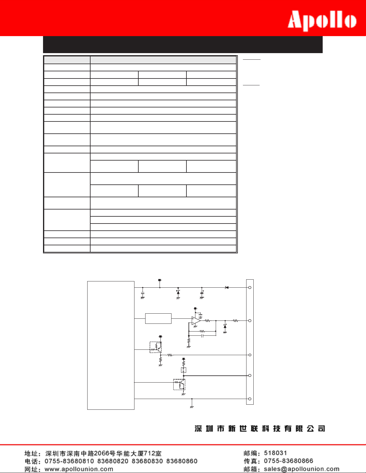
Table 5 - Signal output in operation mode
3. Operation modes
3-1 Warm up
The sensor is warmed up for two hours after the
module is powered on. The green LED blinks on and
off and a constant voltage (0.4V for -L00, 0.2V for -M00,
0.04V for -H00) is output from the concentration
output
port during this period. The green LED will be lit
continuously after the warm-up period ends unless
a power outage occurs.
3-2 CO2concentration lower than threshold level
The green LED will be on if the calculated CO2
concentration is lower than the threshold level.
3-3 CO2concentration exceeds threshold level
The red LED will be lit and the control signal output
is turned “ON” if the concentration exceeds the
threshold level.
The control signal output is turned to “OFF” and the
red LED will be off when CO2concentration drops
to 90% of the threshold level.
3-4 Trouble
When the sensor's output is abnormal, the yellow
LED blinks on and off and the TRBL signal is set to
“ON.
4. Cautions
1) By assuming that the baseline level represents
fresh air (400ppm of CO2), actual CO2concentrations
are calculated based on the difference between the
baseline level and the current sensor output. As a
result, the following cautions should be noted:
a) Accurate readings cannot be expected if an accurate
baseline could not be acquired.
b) The sensor should be exposed to fresh air
periodically to properly renew the baseline level.
Performance shown in the specications cannot be
achieved if the module was used in an environment
where CO2concentrations increased slowly and
steadily for a long period of time.
c) The module should be located in fresh air during
the warm-up period. Accurate readings cannot be
expected until the baseline is acquired in fresh air. If
the module is warmed up in an environment where
CO2concentration is higher than normal fresh air, the
baseline will represent a polluted level and the device
will not be able to clean the air sufciently.
d) Power should be on at all times. Since the baseline
is memorized in a microcomputer, if the power should
be cut off, the memory would be lost and operation
would resume from the warm-up process.
e) The module is not intended for usage in life saving
equipment. If the module is incorporated into life
saving equipment, an alternative and secure measure
for calculating CO2concentration should be used be
used for the life safety function.
2) This module is designed only for indoor usage.
The module should be protected from exposure to
rain, wind, sun, heat radiation, etc.
3) Please apply a regulated voltage, otherwise the
accurate reading cannot be expected. Application
of excessive and/or reverse voltage would cause
damage to the module.
4) The module does not include a circuit for protection
from excessive current. An excessive current
protection circuit should be added to a peripheral
circuit of the module.
5) The sensor may deteriorate if it is stored without
power in a high humidity environment for a long
period of time. Please keep the sensor in a humidity-
proof bag with a desiccant if the sensor is to be stored
without power for a long period of time.
6) Thesensor hasdependency onoxygen concentration.
Under environments where the oxygen concentration
Condition Green LED Yellow LED Red LED Control signal
(CTRL)
Trouble signal
(TRBL)
CO2concentration signal
CDM4160-L00 CDM4160-M00 CDM4160-H00
Warm-up period Blink ON/OFF OFF OFF OFF OFF 0.4V 0.2V 0.04V
CO2 conc < threshold ON OFF OFF OFF OFF CO2conc/1000 CO2conc/2000 CO2conc/10000
CO2 con > threshold ON OFF ON ON OFF CO2conc/1000 CO2conc/2000 CO2conc/10000
Trouble ON Blink ON/OFF OFF OFF ON 4.5V 4.5V 4.5V

Revised 10/12 6
TECHNICAL INFORMATION FOR CDM4160
varies from ambient conditions (i.e. 21% O2), the
sensor may not function properly and may not exhibit
the chracteristics described in this brochure.
7) Please refer to “TGS4160 Technical Information” for
other handling precautions of TGS4160.
5. Important Notice
Figaro Engineering Inc. (Figaro) reserves the right to
make changes without notice to any products herein
to improve reliability, functioning or design.
Information contained in this document is believed
to be reliable. However, Figaro does not assume any
liability arising out of the application or use of any
product or circuit described herein; neither does it
convey any license under its patent rights, nor the
rights of others.
IMPORTANT NOTE
This product is not designed and authorized for use
as a component in life support applications wherein
a failure or malfunction of the products may result
in injury or threat to life. Figaro Engineering Inc.
reserves the right to make changes to this product
without notice to improve reliability, functioning,
and/or design.
This manual suits for next models
2
Table of contents