Fike 63-1052 User manual
1 I56-2475-010
3/25/2020
63-1052, 63-1053, and 63-1057
Intelligent Photoelectric Smoke Detectors
INSTALLATION AND MAINTENANCE INSTRUCTIONS
BEFORE INSTALLING
This detector must be installed in compliance with the control panel system
installation manual. The installation must meet the requirements of the Au-
thority Having Jurisdiction (AHJ). Detectors offer maximum performance
when installed in compliance with the National Fire Protection Association
(NFPA); see NFPA 72.
GENERAL DESCRIPTION
Models 63-1052, 63-1053 and 63-1057 are intelligent photoelectric, spot-
type smoke detectors utilizing sensing chambers that are designed to re-
spond rapidly to a broad range of fires. The sensing chamber employs
features that minimize the effects of settled dust on performance. Model
63-1053 uses a thermistor based, 135°F heat detection circuit in addition to the
photoelectric sensing chamber. The 63-1053 also transmits an alarm signal due
to heat (135°F fixed) per UL 521. 63-1057 is designed for use inside the DN-
RECL duct housing only. 63-1057 should not be used in open area applications.
The detector is designed with tri-color LEDs to indicate detector status. The
detector can be programmed to make the LEDs blink or be steady green, am-
ber or red. The detector remote output can be configured to follow the LED
or be independently controlled. A remote LED annunciator is available as an
accessory (RA400Z/RA100Z).
The 63-1052, 63-1053 and 63-1057 require compatible addressable commu-
nications to function properly. Connect these detectors to listed-compatible
control panels only.
SPACING
System Sensor recommends spacing detectors in compliance with NFPA 72. In
low air flow applications with smooth ceilings, the detectors should be spaced
30 feet apart. For specific information regarding detector spacing, placement,
and special applications, refer to NFPA 72 or the System Smoke Detector Appli-
cation Guide, available from Fike. When using the 63-1053 as a heat detector
in FM3210 compliant applications, space detectors 20 feet apart.
Duct Applications: 63-1052 and 63-1053 are listed for use in ducts. See Duct
Applications Guide HVAG53 (formerly A05-1004) for details on pendant
mount applications.
Note: 63-1057 is listed for use inside DNRECL duct smoke detectors.
WIRING GUIDE
All wiring must be installed in compliance with the National Electrical Code,
applicable local codes, and any special requirements of the Authority Having
Jurisdiction (AHJ). Proper wire gauges should be used. The installation wires
should be color-coded to limit wiring mistakes and simplify system trouble-
shooting. Improper connections will prevent a system from responding prop-
erly in the event of a fire.
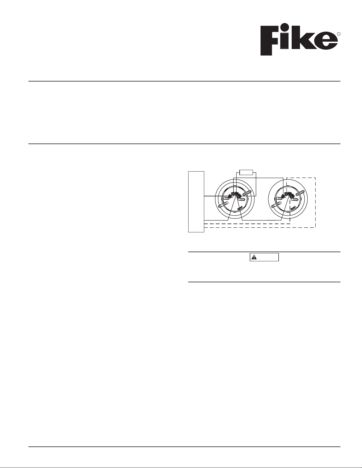
1. Wire the detector base (supplied separately) per the wiring diagram, Figure 1.
2. Install the detector into the base. Push the detector into the base while
turning it clockwise to secure it in place.
3. Set the desired address using the IR configuration tool (model no. EA–CT).
NOTE: Maximum range for the EA–CT is 30 ft. (9 m).
4. Test the detector(s) as described in the TESTING section of this manual.
SPECIFICATIONS
Normal Operating Voltage: 15 to 30 VDC
Standby Current: 481µA max. @ 24 VDC (continuous broadcasts)
Alarm Current: 2 mA max. @ 24 VDC (LEDs on)
Humidity Range: 10% to 93% Relative Humidity, Non-condensing
Temperature Range: 32°F to 120°F (0°C to 49°C ); 63-1052 and 63-1057; 32°F to 100°F (0°C to 38°C); 63-1053
Heat Detector: 135°F Fixed Temperature Electronic Thermistor
Height: 2.1˝ (51 mm) installed in EBFI or EBI Base
Diameter: 6.1˝ (155 mm) installed in EBFI Base; 4.1˝ (104 mm) installed in EBI Base
Weight: 5.2 oz. (147 g)
FIGURE 1. WIRING DIAGRAM
+
–
–
+
LISTED COMPATIBLE
CONTROL PANEL
OPTIONAL RETURN LOOP
+–
1
2
3
4
1
2
3
4
CAUTION: DO NOT LOOP
WIRE UNDER TERMINAL
1, 2 OR 3. BREAK WIRE
RUN TO PROVIDE
SUPERVISION OF
CONNECTIONS.
OPTIONAL
REMOTE
ANNUNCIATOR
C0113-01
NOTE: 63-1057 requires a 5-volt zener diode only when connected to an
RA400Z or RA100Z remote LED annunciator.
CAUTION
Dust covers provide limited protection against airborne dust particles during
shipping. Dust covers must be removed before the detectors can sense smoke.
Remove detectors prior to heavy remodeling or construction.
TAMPER-RESISTANCE
Models 63-1052 and 63-1053 include a tamper-resistant capability that pre-
vents their removal from the base without the use of a tool. Refer to the base
manual for details on making use of this capability.
TESTING
Before testing, notify the proper authorities that the system is undergoing
maintenance, and will temporarily be out of service. Disable the system to
prevent unwanted alarms.
All detectors must be tested after installation and periodically thereafter. Test-
ing methods must satisfy the Authority Having Jurisdiction (AHJ). Detectors
offer maximum performance when tested and maintained in compliance with
NFPA 72.
The detector can be tested in the following ways:
A. Functional
This detector can be functionally tested by using the EA–CT. Follow-
ing the instructions, initiate the detector test sequence. The detector will
then send a test alarm message to the panel. Refer to the control panel
technical documentation for further information.
B. Smoke Entry
The GEMINI model 501 aerosol generator can be used for smoke entry
testing. Set the generator to represent 4%/ft to 5%/ft obscuration as de-
scribed in the GEMINI 501 manual. Using the bowl shaped applicator,
apply aerosol until the panel alarms.
I56-2475-010
704 S. 10th Street
Blue Springs, MO 64015
Phone: 816.229.3405; Fax: 816.228.9277
www.fike.com
R

Additionally, canned aerosol simulated smoke (canned smoke agent)
may be used for smoke entry testing of the smoke detector. Tested and
approved aerosol smoke products are:
MANUFACTURER MODEL
Home Safeguard Industries 25S
SDi CHEK02 and CHEK06
SDi SOLOA4
SDi SMOKESABRE-01
When used properly, the canned smoke agent will cause the smoke detector
to go into alarm. Refer to the manufacturer’s published instructions for proper
use of the canned smoke agent.
CAUTION
Canned aerosol simulated smoke (canned smoke agent) formulas will vary by
manufacturer. Misuse or overuse of these products may have long term ad-
verse effects on the smoke detector. Consult the canned smoke agent manufac-
turer’s published instructions for any further warnings or caution statements.
C. Direct Heat (63-1053 only)
A hair dryer, heat gun, or test apparatus designed for this purpose should
be used to test the thermistors. Direct the heat toward either of the two
thermistors, using care to avoid damaging the plastic housing. The detec-
tor will reset only after it has had sufficient time to cool. Make sure that
both thermistors are tested individually.
A detector that fails any of these tests should be cleaned as described under
CLEANING, and retested. If the detector fails after cleaning, it must be replaced.
When testing is complete, restore the system to normal operation and notify
the proper authorities that the system is back in operation.
CLEANING
Before removing the detector, notify the proper authorities that the smoke
detector system is undergoing maintenance and will be temporarily out of
service. Disable the zone or system undergoing maintenance to prevent un-
wanted alarms.
1. Remove the detector to be cleaned from the system.
2. Remove the detector cover by pressing firmly on each of the four removal
tabs that hold the cover in place.
3. Vacuum the screen carefully without removing it. If further cleaning is
required continue with Step 4, otherwise skip to Step 7.
4. Remove the chamber cover/screen assembly by pulling it straight out.
5. Use a vacuum cleaner or clean compressed air to remove dust and debris
from the sensing chamber.
6. Reinstall the chamber cover/screen assembly by sliding the edge over the
sensing chamber. Turn until it is firmly in place.
7. Replace the cover using the LEDs to align the cover and then gently
pushing it until it locks into place. Make sure that the thermistors do not
become bent under the cover on 63-1053 models.
8. Reinstall the detector.
9. Test the detector as described in TESTING.
10. Reconnect disabled circuits.
11. Notify the proper authorities that the system is back on line.
2 I56-2475-010
©2020 FIKE. 3/25/2020
FIGURE 2. DETECTOR ASSEMBLY
COVER
REMOVAL TABS
SENSING
CHAMBER
SENSING
CHAMBER
COVER AND
SCREEN
SENSOR
COVER
THERMISTORS-
HEAT SENSING
MODELS ONLY
C0349-02
SPECIAL NOTE REGARDING SMOKE DETECTOR GUARDS
Smoke detectors are not to be used with detector guards unless the combina-
tion has been evaluated and found suitable for that purpose.
SPECIAL APPLICATION
When configured at the fire alarm control panel, this detector is capable of op-
erating in a special application mode such that it has a higher sensitivity than
is normally allowed by UL 268 for areas where early warning is important. In
this mode, the detector does not comply with the Cooking Nuisance Smoke
Test. Detectors (Sampling ports) set to the special application mode are not
suitable for use in areas where cooking appliances may be used. If cooking
appliances are used within the protected space, a normal application detector
or normal application mode must be used for that area.
Special application mode is not for general use and the detector may be more
prone to false alarms if used in unsuitable environments. While no list is
all-inclusive, some examples of unsuitable environments for special applica-
tion mode are areas with airborne particulate or aerosols including sawing,
drilling, and grinding operations, textile or agricultural processing, or areas
with engines that are not vented to the outside. A complete list of aerosol and
particulate sources is available in the Annex of NFPA 72.
Suitable environments for special application mode could include early warn-
ing for hospitals, museums, assisted living and other areas that do not have
airborne particulate or aerosols.
Refer to the fire alarm control panel documentation for information on how to
configure the detector for special application mode.
FCC STATEMENT
This device complies with part 15 of the FCC Rules. Operation is subject to the following two conditions: (1) This device may not cause harmful interference,
and (2) this device must accept any interference received, including interference that may cause undesired operation.
NOTE: This equipment has been tested and found to comply with the limits for a Class B digital device, pursuant to Part 15 of the FCC Rules.
These limits are designed to provide reasonable protection against harmful interference in a residential installation. This equipment gener-
ates, uses and can radiate radio frequency energy and, if not installed and used in accordance with the instructions, may cause harmful interfer-
ence to radio communications. However, there is no guarantee that interference will not occur in a particular installation. If this equipment does
cause harmful interference to radio or television reception, which can be determined by turning the equipment off and on, the user is encouraged to
try to correct the interference by one or more of the following measures:
– Reorient or relocate the receiving antenna.
– Increase the separation between the equipment and receiver.
– Connect the equipment into an outlet on a circuit different from that to which the receiver is connected.
– Consult the dealer or an experienced radio/TV technician for help.
Please refer to insert for the Limitations of Fire Alarm Systems
DEVICE AND SYSTEM SECURITY
Before installing this product ensure that the
tamper seal on the packaging is present and
unbroken and the product has not been tampered
with since leaving the factory. Do not install this
product if there are any indications of tampering.
If there are any signs of tampering the product
should be returned to the point of purchase.
It is the responsibility of the system owner to
ensure that all system components, i.e. devices,
panels, wiring etc., are adequately protected to
avoid tampering of the system that could result
in information disclosure, spoofing, and integrity
violation.
This manual suits for next models
2
Table of contents
Other Fike Smoke Alarm manuals


Popular Smoke Alarm manuals by other brands


Climax Technology
Climax Technology SD-29-AC-ZW Series User Manual-Draft

HomeMatic
HomeMatic HM-Sec-SD Mounting instruction and operating manual

Tanda
Tanda TX7120 Installation and operation manual

Elko
Elko Smart Smoke Alarm Battery user guide

First Alert
First Alert 0827 user manual

Teknim
Teknim TSD-5154 installation manual