Fike OSI-RI-FIK User manual

SPECIFICATIONS
Wire Gauge for Terminals: 14 AWG (1.6 mm), 14 AWG (2.08 mm2)
Operating Voltage Range: Without isolator: 15 to 32 VDC (12 or 24VDC nominal, non-polarized),
15-28.5V when using isolators
Maximum Standby Current: 13 mA @ 32 VDC, 14 mA @ 24 VDC, 20 mA @ 15 VDC
Maximum Alarm Current (LED on): 22 mA @ 32 VDC, 15 mA @ 24 VDC, 22 mA @ 15 VDC
Operating Humidity Range: 0% to 95% Relative Humidity, Non-condensing
Operating Temperature Range: –4°F to 131°F (-20°C to +55°C).
UL-Listed for use from 32°F to 100°F (0°C to 37.8°C)
Adjustment Angle: 20 degrees vertical, 50 degrees horizontal
Sensitivity Levels: Level 1 25%, Level 2 30%, Level 3 40%, Level 4 50%
Fault Condition (Trouble): Long-term drift reference out of 20% range, beam blockage or detector out of alignment, imager saturated
Alignment Aid: LED directional arrows
Alarm Indicator: Local red LED and remote output
I56-6957-000
QUICK START GUIDE
704 S. 10th Street
Blue Springs, MO 64015
Phone: 800.979.3453; Fax: 816.228.9277
www.fike.com
OSI-RI-FIK
Smoke Detection System
This guide provides information on how to install the OSI-RI-FIK Smoke De-
tection System.
Extensive product and critical product security information can be found
in the OSI-RI-FIK Installation Guide (Document No. E56-6957) available at
http://www.fike.com/06-912.
The OSI-RI-FIK system consists of an Imager and a reflector. (See Figure 1.)
FIGURE 1. IMAGER AND REFLECTOR
C2051-00, C2052-00
DETERMINE THE POSITIONS OF THE IMAGER AND REFLECTOR
COMPONENTS
Make sure that the intended mounting locations meet the following criteria
(See Figure 2.):
• Detector spacing must comply with local codes and standards
• Reflector must be located within the Field of View (FOV) of the Imager
• Clear path between the reflector and Imager
• Mounted well above the head-height of people and obstructions
• Avoid direct sunlight onto the units
The Imager and reflector should be placed within a recommended distance
below the ceiling. (See Figure 3.) This value will vary according to regional
specifications, geometry, and specific requirements for the installation. The
distance for flat ceilings and basic spacing requirements (S) is shown in the
following table.
Standard Distance from Ceiling Maximum Spacing (S)
NFPA 72 12 in. (300 mm) minimum 60 ft (18.3 m)
AS1670.1 1 to 23.6 in. (25 to 600 mm) 45.9 ft (14 m)
BS5839.1 1 to 23.6 in. (25 to 600 mm) 49.2 ft (15 m)
GB50166 11.8 to 39.4 in. (300 to 1000 mm) 45.9 ft (14 m)
For full information on spacing requirements, please refer to your local codes
and standards.
FIGURE 2. MOUNTING LOCATIONS
12” minimum
(0.3m)
10’ (3.0m)
minimum
Typical
30’
(9.1m) maximum
To First
Detectors
1/2 S S
Wall
C2053-00
FIGURE 3. MOUNTING LOCATIONS
Ex. Distances according to NFPA 72.
1/2 S maximum
ReflectorTx/Rx
S
Tx/Rx Reflector
16 ft. (5m) minimum
328 ft. (100m) maximum
1/4 S
maximum
C2054-00
R
http://www.fike.com/06-912
Fo
r system/product documentation including
installation, operation, and maintenance,
scan QR code or enter URL provided.
1 I56-6957-000
10/21/2020
MOUNT THE REFLECTOR USING THE DRILL TEMPLATE
Refer to Appendix II. in Installation guide for drill template instructions. (See
Figure 4.)
MOUNTING THE DETECTOR
Remove detachable front rim cover. To detach the Imager part from the back-
box, loosen the 3 holding screws.
To provide cable access to the Termination Card of the Imager remove the
cut-outs from the back, bottom or top of the main assembly by using a sharp
blade to cut around the circular discs.
Secure the back box directly onto the mounting surface using any suitable
number of the 5 pilot holes in the backbox.
Use appropriate fasteners to secure the back box component to the mounting
surface.
FIGURE 4.MOUNTING THE DETECTOR
Cable knock-outs
bottom
Cable knock-outs
top
Holes for the fixing
of the detector
Large knock-out
for 4” J-Box
Mounting holes
C2055-00
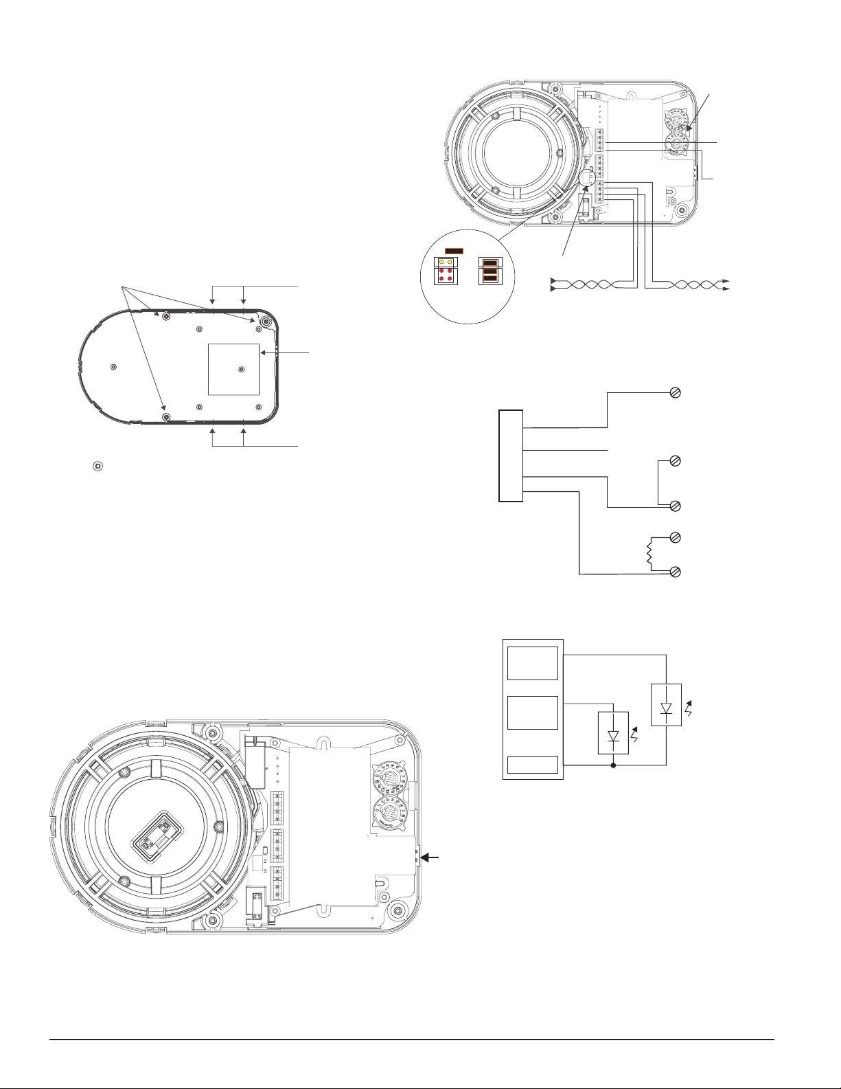
WIRE THE TERMINATION CARD ON THE IMAGER
• Wire the initiating device circuit on the Imager Termination Card using
the addressable loop. (See Figure 5.)
• Wire external power to the unit via the POWER terminals.
• Wire the Remote Indicator and/or remote test or reset units if required
(See Figure 6.).
• Securely connect the wires to the plug-in terminals and engage in the
receptacles at the back of the Imager.
• Switch on the heater if the installation requires so.
• Set the detector address using the rotary switches
• Re-attach the Imager to the back box
• Remove the protective film from the lens surface of the imager.
• Connect power to the Imager.
FIGURE 5. WIRING THE TERMINATION CARD
T3
T2
T1
Not Used
Not Used
Heater Power In -
Heater Power In +
AUX (-)
Remote Test/Reset Input
Remote Trouble Output
Remote Alarm Output
SLC - OUT
SLC - IN
SLC + OUT
SLC + IN
USB
Connector
C2056-00
FIGURE 6. WIRING THE TERMINATION CARD
Heater on/off switch
Communication Line
32 VDC max.
Twisted pair is
recommended
To next
device
From panel
or previous
device
+
-
-
+
Jumper
No heater
Isolator
Heater
No Isolator
heater
shunts
Rotary switches
for setting
the address
Heater
Power
In -
Heater
Power
In +
C2057-00
FIGURE 7. OSI-RI TERMINALS
T1
RTS151/Key
Terminals
T3
T4
T5
T2
OSI-RI-FIK Terminals
External
Jumper
10k ohm
External
Resistor
Remote Alarm Output
Remote Trouble Output
Remote Test/Reset Input
AUX -
T2-1
T2-3
T2-2
T2-4
Wiring: Single 2 pair cable , 0.8mm
2
, unshielded.
C2058-00
FIGURE 8. REMOTE LED CONNECTIONS
Alarm
Signal
Circuit
Trouble
Signal
Circuit
Yellow
Red
T2-1
T2-2
T2-4
Remote LED connections
C2059-00
2 I56-6957-000
10/21/2020
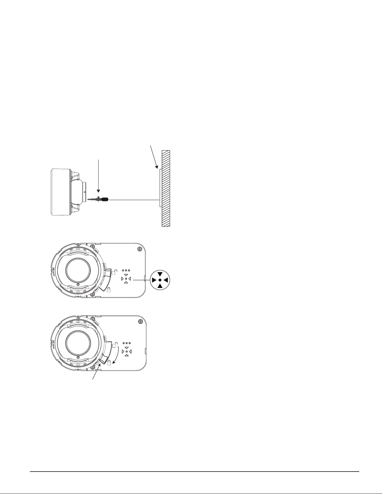
INITIALIZATION AND COMMISSIONING
Ensure that neither you nor any other objects are in the line of sight between
the detector and the reflector and start to manually align the Imager to the
reflector (See Figure 9.)
The OSP-002 Laser Alignment Tool can be used for the rough alignment if
the system is to be installed at longer distances or in heavy lit environments.
Follow these steps to adjust the optical sphere of the detector component to
align the system (See Figure 10.):
• Make sure the lever is the 3 o’clock position.
• The 4 arrows will intuitively guide the user to optimal eyeball alignment.
Likely the alignment process will start with all arrows red.
• Gently move the eyeball until all arrows and the middle green LED blink
green for the eyeball to be optimal aligned (See Figure 11.).
• When all arrows are green, gently lock the eyeball by moving the lever
down till the eyeball is solidly locked. The lever is now in the 5 o’clock
position and you feel the resistance of the locked position.
FIGURE 9. COARSE ALIGNMENT
OSP-002 Laser
Alignment Tool
Reflector
C2060-00
FIGURE 10. ARROW ARRAY
C2061-00
FIGURE 11. LOCKING AND SECURING EYE BALL
Level down
C2062-00
By locking the eyeball an internal switch is activated and the detector will
now start its initiation or commissioning process. A normal commissioning
process takes roughly 10 seconds. During the commissioning process, the
beam path must remain clear from object intrusions.In this process cycle, the
detector will measure the size of the reflector in the FOV and set the sensitiv-
ity automatically to the optimum sensitivity for the specific distance.
Before going in operational mode, the detector will show its set sensitivity.
This is shown by blinking the 4 arrows to the color yellow, reflecting the % of
selected obscuration/sensitivity. The key is; 1 blink = 25%, 2 blinks = 30%,
3 blinks = 40% and 4 blinks = 50%. After 5 seconds, the scenario will be re-
peated a second time and the arrows LEDs go out and the front OK LED blinks
green. The detector is now in operation and working correctly.
The paintable rim can now be snapped over the front to secure the locking
lever and to hide the alignment LEDS and locking mechanism.
Applying the cover also secures the locking lever in position.
TESTING THE INSTALLATION
After the commissioning, the detector must be tested for correct alarming by
using the OSP-004 test filter at the reflector or using the remote test station.
When using the RTS151KEY for testing the detector, the remote fault LED will
blink the set sensitivity of the detector. The number of blinks, similar to sec-
tion 5, will represent the set sensitivity and the sequence is repeated every 3
seconds till the detector is reset.
IMAGER RESET
The fault LED is non-latching but the alarm LED can be set to latching by the
FACP. The Imager alarm can be reset from the FACP.
OPERATION AFTER A POWER FAILURE
After a power failure of any duration, when the supply is restored, the detec-
tor will check the possible new situation versus its memorized data.
If the reflector is found in the same position and all parameters are within
acceptable limits, the detector will resume its operation and go out of fault
condition.
If any significant parameters have changed, it will remain in a fault condition
and a re-initialization will be required.
3 I56-6957-000
10/21/2020

Fike® is a registered trademark of Fike Corporation.
OPERATION MODES AND TROUBLESHOOTING GUIDE OSI-RI-FIK
Modes Red and Re-
mote Alarm
output
Yellow and
Remote Trouble
Output
Green Initiating meansComments & Troubleshooting Tips
Power on Off Blink Off Apply Power from dis-
charged state
• All wiring correctly done.
• Address switches set.
Alignment Off Blink Off Lever in 3:00 position and
commissioning is active
• Ready to perform alignment.
• Follow guidance from the 4 arrows to correctly align.
Initializing/
Commissioning
Off Blink Off Lock lever in 6:00 position
to start commissioning
• Commissioning and setting sensitivity.
• Do not interrupt beam.
Normal Off Off Blink Successful completion of
initialization or detector
reset
• Initializing finished.
• Detector operates normal in quiescent condition.
• Detector successfully reset.
Alarm On Off Off Smoke, Test Filter or RTS-
151KEY Test Station
• Blinks till reset from FACP.
Trouble-Drift
Compensation
Off 3 Quick Blinks Blink Long Term Drift Reference
Out of 20% Range
• Reduced IR Signal
• Clean detector and reflector.
Trouble-Beam
Blockage
Off 4 Quick Blinks Blink Beam blockage or detector
out of alignment
• Remove blockage or re-align detector
• Faulty unit.
Trouble-Imager
saturation
Off 5 Quick Blinks Blink Imager saturated • Sunlight or very strong light into detector or reflector.
• Re-position detector or reflector.
• Remove light source.
Test activated-
Pass Result
On Blinks the set sen-
sitivity by number
of blinks (1-4).
Repeats every 3
seconds till reset.
Off FACP or RTS151KEY • Remains in alarm until reset by FACP.
• Number of lit arrows indicates sensitivity level that
was selected automatically.
4 I56-6957-000
©2020 Fike. 10/21/2020
Other Fike Smoke Alarm manuals


