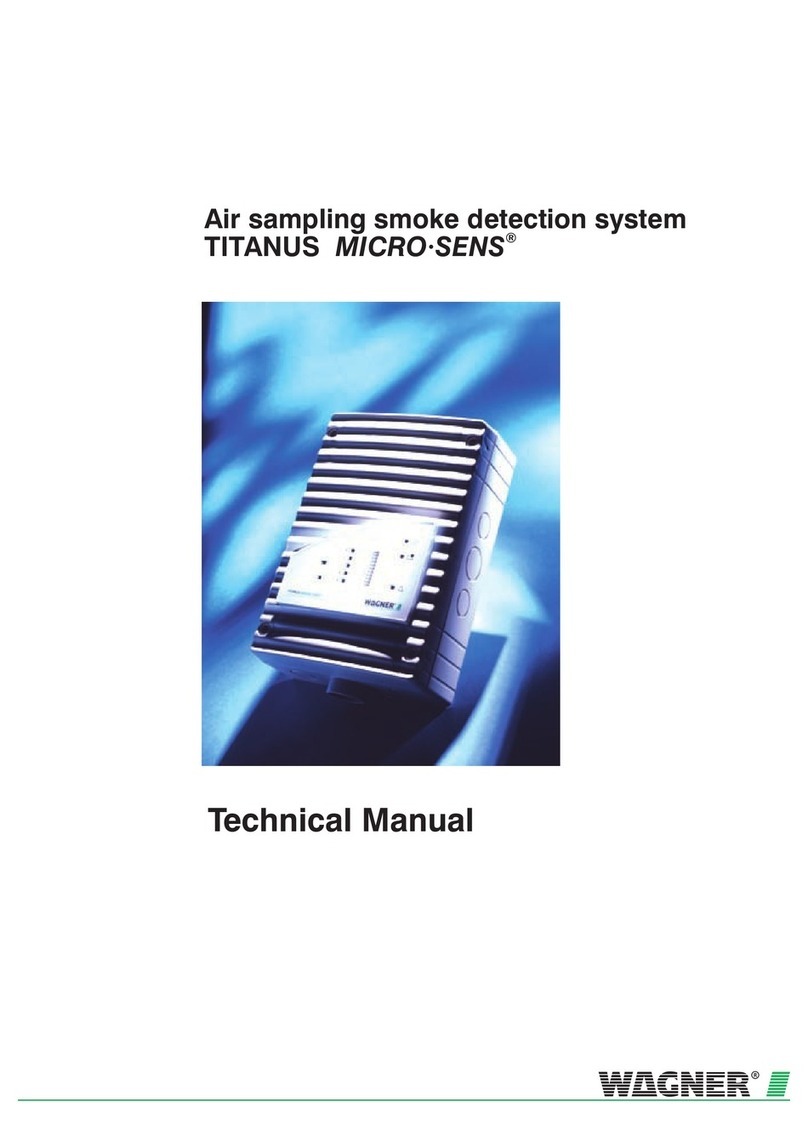
WAGNER TITANIUS TOP-SENS User manual

Air sampling smoke detection system
Fire Detection
TITANUS
TOP·SENS
® /Rev.a
Technical Manual


Air sampling smoke detection system
TITANUS
TOP·SENS
® /Rev.a
Technical Manual
WAGNER Group GmbH
Schleswigstraße 1 - 5
D-30853 Langenhagen
Telephone +49 (0) 511 / 97383-0
Telefax +49 (0) 511 / 97383-140
E-Mail suppo[email protected]
Internet www.wagner.de
Item Number 69-30-0335
Edition 06/13
Supersedes 04/09


TITANUS
TOP·SENS
®/Rev.a
06/113 5
Contens
1 General 13
1.1 Introduction 13
1.2 Safety Information 13
1.3 Warranty 14
1.4 Copyright 14
1.5 Packaging 14
1.6 Disposal 15
2 Product Description 17
2.1 Features of the TITANUS® air sampling smoke detection system 17
2.2 Areas of Application 19
3 Technical Description 23
3.1 System Description 23
3.1.1 Functions 24
3.2 TITANUS
TOP·SENS
® and accessories 28
3.2.1 Overview 28
3.2.2 Basic device TITANUS
TOP·SENS
® 29
3.2.3 Diagnostics 31
3.2.4 Network modules 32
3.2.5 Remote displays 34
3.2.6 Device supports 35
3.3 Pipe system 36
3.3.1 Overview of available pipe components 36
3.3.2 Air sampling points for room monitoring 38
3.3.2.1 Aspiration reducing film sheets 38
3.3.2.2 Air flow reducer clips 39

TITANUS
TOP·SENS
®/Rev.a
/Rev.a
6 06/13
3.3.2.3 Ceiling feed-through for hidden installations 40
3.3.3 Air filter for dusty areas 42
3.3.4 Air return for pressurised and dusty areas 45
3.3.5 Noise suppressor 46
3.3.6 Steam trap for humid areas 47
3.3.7 Detonation prevention device for endangered areas 49
4 Technical Data 51
4.1 TITANUS
TOP·SENS
® 51
4.1.1 Accessories - TITANUS
TOP·SENS
® 55
4.1.2 Pipe system TITANUS
TOP·SENS
® 55
5 Design 57
5.1 General 57
5.1.1 Regulations 58
5.1.2 Pipe systems 59
5.1.3 Air flow monitoring 64
5.1.4 Sensitivity 66
5.1.5 Project planning limits 67
5.2 Project planning 68
5.2.1 Project planning guidelines 68
5.2.1.1 Determining the necessary accessories 68
5.2.2 Pipe accessories 69
5.2.3 Sensitivity and pipeline project planning 70
5.2.3.1 Pipeline project planning with pipe accessories 70
5.2.4 Aperture diameter 74
5.3 Special project planning 79
5.3.1 Project planning for individual aperture monitoring 79
5.3.1.1 Pipe system 79

TITANUS
TOP·SENS
®/Rev.a
06/113 7
5.3.1.2 U-pipe system 81
5.3.1.3 M-pipe system 83
5.3.1.4 Double U-pipe system 85
5.3.2 Special project planning 87
5.3.2.1 I-pipe system 87
5.3.2.2 U-pipe system 88
5.3.2.3 M-pipe system 89
5.3.2.4 Double-U-pipe system 90
5.3.3 Project planning with branch pipes 92
5.3.4 Project planning with long intake lines > Ø 25 mm 95
5.3.5 Project planning with acceleration apertures 97
5.3.6 Project design for forced air flow 103
5.3.7 Project design with air sampling hose 107
5.3.8 Project planning with air return 109
5.4 Mains supply 111
6 Installation 113
6.1 General 113
6.2 Opening the air sampling smoke detection system 114
6.3 Settings 115
6.3.1 Detector module 115
6.3.1.1 Setting of response sensitivity 115
6.3.1.2 Delay period of alarm activation 116
6.3.1.3 Activating threshold for air flow monitoring 116
6.3.1.4 Delay period for air flow fault 117
6.3.1.5 Fault signal 117
6.3.1.6 LOGIC·
SENS
117
6.3.1.7 Setting of fan voltage 118
6.3.1.8 Connecting the fan 119

TITANUS
TOP·SENS
®/Rev.a
/Rev.a
8 06/13
6.3.1.9 Setting of ventilator voltage at TITANUS®-SL 119
6.3.1.10 Connecting the fan TITANUS® -SL 120
6.4 Installation of the reset board 122
6.5 Mounting Location 125
6.5.1 Installation of air sampling smoke detection system 125
6.5.2 Connection of air sampling pipe 128
6.6 Electrical connection 129
6.6.1 Connection to FAS, with reset button 131
6.6.2 Connection to FAS with reset board 133
6.7 TITANUS® for external shutdown 134
6.7.1 Installation of the shutdown modules 134
6.7.2 Connecting the shutdown module 136
6.7.3 Activating the shutdown 137
6.8 Networking TITANUS® 138
6.8.1 Installing the network module 138
6.8.2 Connecting the network module 139
6.9 Installation of second detector module 141
6.10 TITANUS® with remote display units 143
6.10.1 Connecting the remote display unit 143
6.10.2 Remote display unit housing 144
6.10.2.1 Attaching front panel 144
6.10.3 Remote display unit for 19’’ inserts 145
6.10.4 Electrical Connection 146
6.11 Data-Log 147
7 Installation of the pipe system 149
7.1 General assembly 149
7.1.1 Mounting pipe system 150

TITANUS
TOP·SENS
®/Rev.a
06/113 9
7.1.2 Mounting air sampling hose 151
7.2 Linear expansion of the pipe system 153
7.3 Patented aspiration apertures 155
7.4 Ceiling lead through 157
7.4.1 Ceilings feed-through for false ceiling 157
7.4.2 Other ceilings feed-through 158
7.5 Monitoring in forced air flow systems (ventilation or climatic applica-
tions)
160
7.5.1 Detection at air inlets/outlets 160
7.5.2 Detection in bypass systems 160
7.6 Filter 162
7.6.1 Installation of air filter, type LF-AD-x 162
7.6.2 Mounting of the special filter type SF-400/650 163
7.7 Air return 165
7.8 Noise suppressor 166
7.9 3-Way ball valve 168
7.10 Steam trap 170
7.10.1 Steam trap Type KA-DN-25 170
7.10.2 Steam trap Type KA-1 171
7.11 Detonation prevention device 172
7.12 Test adapter 174
8 Commissioning 175
8.1 Adjustment Air Flow Sensor 176
8.1.1 Adjustment independent of the air pressure 177
8.1.2 Adjustment dependent on the air pressure 178
8.2 Check detector module and alarm transmission 180
8.3 Check air flow monitoring 181

TITANUS
TOP·SENS
®/Rev.a
/Rev.a
10 06/13
8.4 Check Fault Signal Transmission 182
8.5 Operational check of TITANUS
TOP·SENS
® 183
8.5.1 Preparations for the operational check 183
8.5.2 Carrying out operational check 184
9 Maintenance 187
9.1 Visual check 187
9.2 Flash code table 187
9.2.1 1x Flashing (Fault: Internal Voltage Monitoring 1) 189
9.2.2 2x Flashing (Fault: Internal Voltage Monitoring 2) 190
9.2.3 3x Flashing (Fault: Monitoring of Fan Voltage) 191
9.2.4 4x Flashing (Fault: Monitoring of Air Pressure Adjustment Voltage ) 192
9.2.5 5x Flashing (Fault: Programme Error) 193
9.2.6 6x Flashing or 7x Flashing (Internal Fault 1 and 2) 193
9.2.7 8x Flashing (Device-Initialising) 194
9.3 Check detector module and alarm transmission 195
9.4 Check pipe system 195
9.5 Exchange of detector module 196
9.6 Changing the air filter LF-AD-x 198
9.7 Changing special air filter SF- 400/650 199
9.8 Check the air flow sensor adjustment 200
9.9 Check air flow monitoring 203
9.10 Check fault signal transmission 203
9.11 Maintenance intervals 203

TITANUS
TOP·SENS
®/Rev.a
06/113 11
Appendix
Air Pressure Adjustment Tables
Projection Tables
System Product List
Inspection Protocol
Glossary
Conformity certification pursuant to EU

TITANUS
TOP·SENS
®/Rev.a
/Rev.a
12 06/13

TITANUS
TOP·SENS
®/Rev.a General
06/13 13
General
Introduction
This manual is for installers of air sampling smoke detection systems, in par-
ticular for engineers, technicians, and fitters etc. who have technical knowl-
edge in the field of smoke detection technology but who are possibly working
with this device for the first time.
For damage and faults resulting from the non-observance of this manual
WAGNER Group GmbH, called WAGNER in the following, does not assume
liability.
This manual refers to the air sampling smoke detection systems TITANUS
TOP·SENS
® and TITANUS
TOP·SENS
®
2, these systems may only be used
for early and very early smoke detection. As the smoke detection systems
are from one series, TITANUS
TOP·SENS
®
is described here. Specific tech-
nical designs of TITANUS
TOP·SENS
®
2 are described separately.
Safety Information
The following symbols identify parts of the text in this manual which re-quire
special attention so that damage can be avoided and so that operations can
run smoothly.
WARNING
This symbol warns against actions,
which might cause damage if it is ignored.
NOTICE
This symbol warns against actions,
which could cause operational breakdowns if it is ignored.
TIP
Operational improvements can be achieved if this symbol is observed.
1
1.1
1.2

General TITANUS
TOP·SENS
®/Rev.a
14 03/14
Warranty
The manual is subject to technical modification without notice and makes no
claim to completeness.
In principle our “Terms and Conditions of Supply and Assembly” apply. No
claims under the guarantee or for liability can be made for damage to per-
sons or property if they are based on one or more of the following causes:
▪ insufficient observance of the instructions about the design, assembly of
the aspirating smoke detection system, assembly of the pipe system,
commissioning and maintenance
▪ use of the aspirating smoke detection system in contravention of the in-
tended use
▪ insufficient monitoring of working parts
▪ improperly executed repairs
▪ unauthorised constructional changes to the aspirating smoke detection
system
▪ force majeure
Copyright
The copyright in this Technical Manual remains with WAGNER.
The manual is designed exclusively for the assembler and his colleagues.
Reproduction of the manual, including extracts, is not allowed. Copying or
distribution of the manual in any form is only allowed with permission in writ-
ing from WAGNER.
Packaging
The individual air sampling smoke detection systems are packed in accor-
dance with the anticipated transport conditions. Exclusively environ-mentally
friendly materials were used for the packaging.
The packaging is intended to protect the air sampling smoke detection sys-
tem from being damaged until it is installed. For that reason, it should only
be removed from its packaging shortly before installation.
The packaging material is to be disposed of in accordance with applicable
statutory provisions and local regulations.
1.3
1.4
1.5

TITANUS
TOP·SENS
®/Rev.a General
06/13 15
▪ Dispose of the packaging materials in an environmentally friendly man-
ner.
▪ Observe local disposal regulations.
NOTICE
Packaging materials are valuable raw materials and in many cases can be
re-used or expediently processed and recycled. Improper disposal of pack-
aging materials can harm the environment.
Disposal
If no take-back or disposal agreements have been made, disassembled
components are to be taken for recycling:
▪ Take metal parts for scrapping.
▪ Take plastic parts to be recycled.
▪ Sort the remaining components by material quality and dispose of them.
▪ Give batteries to municipal collecting points,
or send them back to WAGNER Group GmbH.
1.6


TITANUS
TOP·SENS
®/Rev.a Product Description
06/13 17
Product Description
Features of the TITANUS® air sampling smoke
detection system
TITANUS
TOP·SENS
® is the latest generation of the renowned WAGNER
air sampling smoke detection systems. Besides its use for room and equip-
ment protection the more sensitive system can be used for monitoring cli-
matic cabinets and ducts.
The device has a display sensitivity of 0.05%/m to 0.0015%/m light obscura-
tion. According to application, further sensitivities can be set. Thanks to the
innovative High-Power-Light-Source technology a wide detection range is
achieved for all types of fire.
The area to be monitored can be doubled if two detector modules are used
in TITANUS
TOP·SENS
®. There are three alarm levels for each detector
module – alert alarm, action alarm and fire alarm. These can be separately
controlled via voltage-free contacts.
The set sensitivity of the detector modules can be adjusted one step lower
via an additional input.
In order to prevent false alarms, the intelligent signal processing called
LOGIC
·SENS
distinguishes between interferences and the occurrence of
real fire.
Like spot-type detectors, which are electronically monitored in order to detect
line fractures and short circuits, air sampling systems require complex and
safe air flow monitoring. The unique air flow sensor technology used in all
WAGNER air sampling smoke detection systems guarantees the detection
of faults such as pipe fractures or blockages of air sampling points.
The low-level air flow is equipped with a dynamic air flow sensor in order to
detect small and quick changes.
Air flow monitoring is temperature compensated and can be adjusted de-
pending on the air pressure.
A special feature of TITANUS® is its ability to network the system. With an
optional network card in TITANUS® several smoke detection systems can be
linked to one network. The operator can oversee the entire system from a
central control point and observe the smoke level, air flow data etc.
Depending on the required pipe design the air sampling points have defined
hole diameters. For these exact air sampling points WAGNER has devel-
2
2.1
Sensitivit
y
A
lternative sensitivit
y
LOGIC
·SEN
S
Safe airflow monitoring
Networkabilit
y
Patented detection points

Product Description TITANUS
TOP·SENS
®/Rev.a
18 06/13
oped patented aspiration-reducing film sheets with marking tape and clips
that permit an easy mounting and avoid secondary noise. Another advan-
tage is the quick and easy retrieval and check of the air sampling point di-
ameters.
The system’s air sampling points can be compared to spot-type detectors.
The monitoring areas can therefore be designed according to the relevant
valid national regulations.
The diagnostic software permits quick and reliable fault finding for mainte-
nance and service. The current device condition and any saved data can be
downloaded to a PC via a special interface.
The fan voltage can be set according to project planning by re-plugging the
plug-in jumpers.
With TITANUS
TOP·SENS
® devices, the fan voltage can be set between 6.9
V and 9 V by means of the plug-in jumpers on the main board.
The voltage with TITANUS
TOP·SENS
®-SL devices can be set by means of
the fan control circuit boards FC-2 and FC-3.
▪ The voltage can be set to 6.5 V, 6.9 V and 9 V with the FC-2 fan control
circuit board. The FC-2 fan control circuit board is standard in all TITA-
NUS
TOP·SENS
® -SL devices.
▪ The voltage can be set to 10 V, 11 V and 12 V with the FC-3 fan control
circuit board. The FC-3 fan control circuit board available as an option for
all TITANUS
TOP·SENS
® -SL devices.
External devices of TITANUS
TOP·SENS
® (e.g. fan, calculator) can be
switched off with the shutdown module modules. The shutdown is made with
a monitored two-detector-dependent connection.
Spot detector spacing
Diagnostics
Choice of fan voltage
Shutdown module

TITANUS
TOP·SENS
®/Rev.a Product Description
06/13 19
Areas of Application
The air sampling smoke detection system TITANUS® is a technology used
for early smoke detection and very early smoke detection for rooms and
equipment.
Air samples are drawn from the protected area via a pipe system with de-
fined air sampling points and passed to the detector module.
It is particularly suitable for areas in which spot-type detectors cannot be
used or only under certain conditions.
In particular these are areas:
▪ with high fire risk
▪ where a high detection sensibility is required
▪ with limited access and where spot-type detectors are difficult to install or
service
▪ which are air conditioned
▪ which have a greater height than admissible for spot-type detectors
▪ where spot-type detectors are undesirable for aesthetic reasons
▪ where electromagnetic fields have an impact
▪ which are exposed to high or low temperatures
▪ where filters are required due to impurities in the atmosphere
▪ which must be protected from vandalism
2.2
Principle

Product Description TITANUS
TOP·SENS
®/Rev.a
20 06/13
TITANUS® is suitable for:
Rooms such as:
▪ floor voids, ceiling voids
▪ tunnels, ducts, voids with difficult access
▪ storage areas, high-rack storage, elevator shafts
▪ museums, cultural centre
▪ deep-freeze storage
Figure 1: Principle: Room monitoring with the TITANUS® air-sampling smoke detec-
tion system
Room protection
This manual suits for next models
1
Table of contents
Other WAGNER Smoke Alarm manuals