FINE mechatronics FS-8000 User manual

Digital
Weighing Indicator
INSTRUCTION MANUAL
F
S-8000

---------------------------------------------------------------------------------
FINEMECHATRONICS FS8000 2
●
●
●
●
●
●
CONTENTS
●
●
●
●
●
●
CHAPTER 1. PREFACE
1-1 INTRODUCE....................................................3
1-2 SAFTY CONDITIONS.................................... 3
1-3 FEATURES...................................................... 4
1-4 FRONT PANEL DESCRIPTION................. 5
1-4-1 LAMP................................................................ 5
1-4-2 HOW TO USE KEY...................................... 6
1-5 REAR-SIDE PANEL...................................... 9
1-6 SPECIFICATION............................................. 11
1-7 THE EXAMPLE FOR THE CONNECTING
TOEXTERNAL DEVICES.......................... 12
CHAPTER 2. INSTALLATION
...................................... 13
2-1 OUT-DIMMENSION & CUTTING SIZE... 14
2-2 ASSEMBLE DRAWING.................................15
2-3 HOW TO CONNECT LOADCELL............. 16
2-4 ERROR & A/S...............................................
17
CHAPTER 3. CALIBRATION.................
...................
18
3-1 ZERO ADJUSTMENT................................... 18
3-2 SPAN CALIBRATION....................................20
3-3 ERROR MESSAGES & ADJUST............. 24
CHAPTER 4.
SET-UP
......................................................
27
4-1 PREFACE........................................................ 27
4-2 SET-UP........................................................... 27
4-3 F-FUNCTION SUMMARY LIST................ 29
CHAPTER 5. SET-UP ILLUSTRATION
.................
30
5-1 BASIC FUNCTION FOR WEIGHING........ 30
5-2 BASIC FUNCTION FOR DEVICES........... 32
5-3 SERIAL INTERFACE .................................37
5-3-1 RS-232C SERIAL INTERFACE.................. 38
5-3-2 OP-02 CURRENT LOOP............................
40
5-4 ADDITIONAL SET UP FUNCTION............
42
5-4-1 OP-03 BCD OUT................................... 42
5-4-2 OP-04 RS-422/485 SERIAL ................ 44
` 5-4-3 OP-05/06 ANALOG OUT........................... 45
5-4-4 OP-07 PRINTER....................................
48
5-4-5 OP-10 BCD INPUT................................ 50

---------------------------------------------------------------------------------
FINEMECHATRONICS FS8000 3
CHAPTER
1. PREFACE
1-1. INTRODUCE
Thank you very much for your purchasing FINE Digital Weighing Indicator of FS-8000.
This Instruction Manual will make you lead to use FS-8000 with FINE speed,accuracy,reliability.
FS-8000 is designed to withstand harsh environmental conditions and is designed for flawless
Performance in your demanding application.
Also,FS-8000 have several options that is both versatile and easily connectable to other devices.
※APPLICATION
1. PACKING EQUIPMENTS FOR MANUAL WEIGHING
2. EQUIPMENTS FOR PLATFORM,TANK,TRUCK SCALE
3. EQUIPMENTS FOR STRAIN/COMPRESSION TESTER
4. RECORD-MANAGEMENT FOR PRODUCT WEIGHT
☞REMARK
- This Specification is subjected to change for improvement without prior notice.
- This Version Number will be increased as it graded up.
1-2. SAFTY CONDITIONS
Please keep the following conditions for safe environment.
◆EARTH
To avoid an electric error such as a noise,electrostatics in your production line
It cetainly should be earthed before installation
Specially in case of thunderbolt,it had better devide the power of Indicator into a load cell.
◆SAFTY CONDITIONS
Don`t use it at the environment close to a explosive gas and an inflammable dust environments
◆POWER
Use the power under 110/220V 50/60HZ ±10% and devide it into the power line
◆
TEMPERTURE CONDITIONS
OPERATING TEMPERTURE : -10o C ∼+40o C ( +14oto 104oF )
CUSTODY TEMPERTURE :
-40o C ∼+80o C ( -40oto 176oF )

---------------------------------------------------------------------------------
FINEMECHATRONICS FS8000 4
◆
INSTALLATION LOAD CELL
- Available to use Max.8pcs of the same Load cell of ( 300Ωcriterion )
- It should be horizontal to ground
- In case of Installing over 2pcs of load cell,Connect each line in parallel and
Insert a precise variable resistor under 50Ωin EX + line.
Andd minimize a output deviation of a load cell.
It may occur a weight error according to several deviation of a load cell.
- It may occur a weight error accoding to a temperture variation of load cell
- Please don`t weld(electospark) at the place where a load cell and equipments were installed,
However,Please devide the power into a connector of load cell in inevitable case
- Please connect the above and below construction of a load cell to the weighing part
Weighingaproducts electrosparks may be occurred.
1-3. FEATURES
- A compact Appearance by DIN regulations ( DIN 192 x 96 Panel Insertion )
- Easy to set up, change,confirm several values by the numeral key.
- Improved a convenience and precision of operating by Message Function.
- Can display a various information by F1,F2,F3 key for the end-user.
- Can make several key function use or disuse.(SETUP F10 Reference)
- Back up of Weight even electrospark case (SETUP F02 Reference)
- The permit or prohibition function of Calibration (ADJUST NO 10 Switch)
- Watch-Dog timer guards for self-diagnostics.
- Set up to Max. 1/20,000 display resolution
- Function available to change the unit value such as
kg, ton
, lb ,g
( In case of Serial Interface & Printer )
- Available to change the function of the external input terminal (SETUP F16 Reference)
- Various option Functions for customer`s satisfaction such as RS-422/485, Current Loop,
Analog out, BCD Input/Output and so on.
- RS-232C Serial Interface & Printer was installed basically
- Avilable to print by either Serial Interface or Centronics Parallel Interface

---------------------------------------------------------------------------------
FINEMECHATRONICS FS8000 5
1-4. FRONT PANEL DESCRIPTION
1-4-1. LAMP
▼STEADY : This Lamp will be turned on the stable weight
The condition of STEADY Lamp can set up by F04,F08.
Also,it will be a certerion of weighing for auto function operating.
▼ZERO : This Lamp will be truned when the weighing device is empty.
The condition of ZERO Lamp can set up by F03,F13.
Also,it will be a certerion of weighing for auto function operating.
▼TARE : This Lamp will be displayed when TARE weight was set up
(SET-UPF12REFERENCE)
▼GROSS : This Lamp will be displayed when the present weight was GROSS.
Avilable to display When TARE was set up.
▼COM. : This Lamp will be displayed when Serial Interface was connected to
Externaldevices
▼HOLD : This Lamp will be displayed when HOLD works (SETUP F25 REFERENCE)
▼AUTO : This Lamp will be displayed when AUTO works (SETUP F24 REFERENCE)
F1 F2 F3
COUNT G/T S/T
kg
CODE AUTO
HOLD
CLR SET
CAL
PRINT
FS-8000
STEADY ZERO TARE GROSS COM. HOLD AUTO
ZERO TARE
GROSS
NET PART

---------------------------------------------------------------------------------
FINEMECHATRONICS FS8000 6
1-4-2. HOW TO USE KEY
* The Key operating can be permitted or prohibited by SETUP-F10
* When pushing the key,it sounds "OK".
* Several Key works either a single function or compound functions.
A compound function key is the command key when it push first and
In case of setting value according to the command key,then the numeral Key works.
Finally The key to finish a input data is SET Key.
* The time to input a data by compound key is limited to 5sec and automatically
Will be removed without the next key inputting.
☞ZERO Key :This key is to return to ZERO when the weighing device is empty(the end-user
Selected within 2%, 10%, 50%, 90% by SET-UP F07)
☞TARE Key : The way to set-up the tare weight is two way as follows.
◆Manual Way
1.Set-upofTAREKey
①Put a TARE on the weighing plate
②TARE Key →SET Key OR TARE Key →Numeral Key →SET Key
2.Remove of TARE Key
①Remove TARE on the weighing plate
②Push TARE Key and push SET Key.
◆Automatic Way
1.Auto-TARE setting if TARE was on the weighing plate
2.Auto-TARE setting after putting TARE and Auto-TARE Remove
After Taking away TARE on the weighing plate.
※Please refer to SETUP F12
☞Gross/Net Key : After setting TARE,This key is to convert Net Weight to Gross Weight
And Gross Weight to Net Weight.
* Available to convert TARE setting only
* Gross Lamp turn on when Gorss Mode works.
☞PART Key : Usable to confirm or change the product part
* Can set up the data of each product from 1 No to 20 No.
- Checking PART : PART Key →CLR Key
- Changing PART : PART Key →Numeral Key →SET key

---------------------------------------------------------------------------------
FINEMECHATRONICS FS8000 7
☞F1,F2,F3 Key : This keys appear a various data as the end-user demands.
Available to use the end-user demanding by SETUP F21,F22,F23
( SET UP F21 REFERENCE )
☞COUNT Key : This Key appears the worked frequence of each PART.
* Unavailable to change the PART deliberately.
☞G/T KEY :The function to print The weight of Gross Total
* Avavailable to remove Gross Total in printing.
☞S
/T KEY :The function to print The weight of Sub Total.
* Available to remove Sub Total in printing
☞CODE KEY: The function to check and set Max.6figure CODE of Each PART.
* Checking CODE.
:CODEkey →Checking→CLR(Remove)
* Change or setting CODE.
:CODEkey →Inputting changed Key →SET(Change or setting)
☞HOLD Key : This key is to set/delete HOLD Functions.
* Possible to choose various functions by SET UP F25.
- Manual HOLD : Holding the moment weight value by HOLD Key
- Manaul HOLD(Average) : Holding Average weight value after pushing HOLD Key
- A stable hold : Holding the weight value when being stable
- Maxium HOLD(1Time only) : Holding the maxium weight value when being maxium
- Maxium HOLD (Continue) : Holding a continuous maxium weight
Whenbeingnewmaxium
☞AUTO Key : This key is to set/delete AUTO Function.
* Possible to choose various functions by SET UP F24.
- Auto-totallization in holding the weight.
- Available to work the HOLD function by AUTO setting Only.
- Available to work the HOLD function by AUTO setting Only
And to remove the HOLD function when it empty.
- Auto-totallization when the weight is safty
* Possible to choose AUTO/MANUAL by SET UP F19 when the power is ON.

---------------------------------------------------------------------------------
FINEMECHATRONICS FS8000 8
☞PRINT Key : This Key is to Transmit,Totalize,Print a DATA
* Unavailable to work it while Auto Mode
* Please push CLR + Print when deleting the last TOTAL date.
Only Unavailable to re-power,change the PART,Available 1time only
(The last total data will be deleted also on Auto-total)
☞CLR Key : This have 4way to use as folllows .
1) When cancelling it with inputing the setting value
2)
CLR + TOTAL(+TOTAL) +SET When setting the total data.
3)
CLR + Print when deleting the last TOTAL date
4) When using SETUP or CALIBRATION ( 3Chapter, 4Chapter REFERENCE)
* After
CLR Key,If no a addtional data,it will be deleted automatically. .
☞SET/CAL Key : SET key have 2way to use as follows
1) When recording each setted data
2) When using SETUP or CALIBRATION( 3Chapter, 4Chapter REFERENCE)
---------------------------------------------------------------------------------
FINEMECHATRONICS FS8000 9
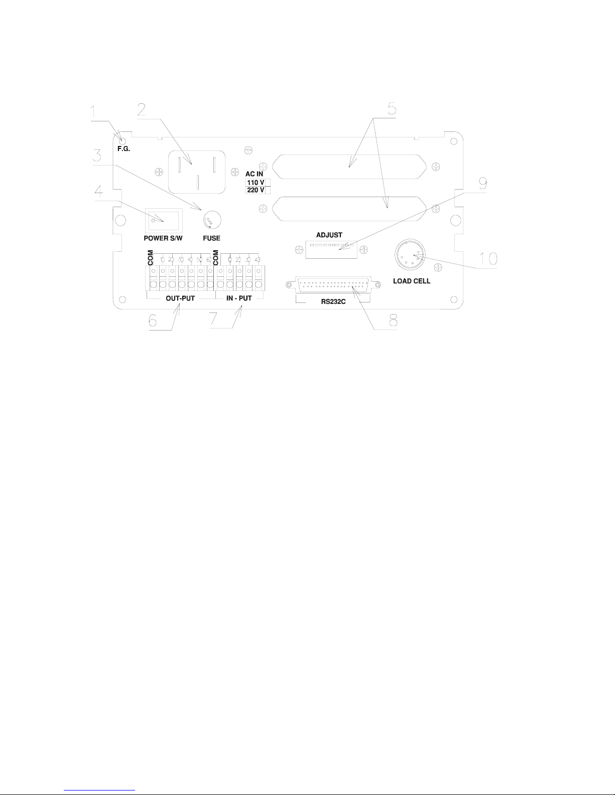
1-5. REAR-SIDE PANEL
1.F.G.:
Please earth it for safe.
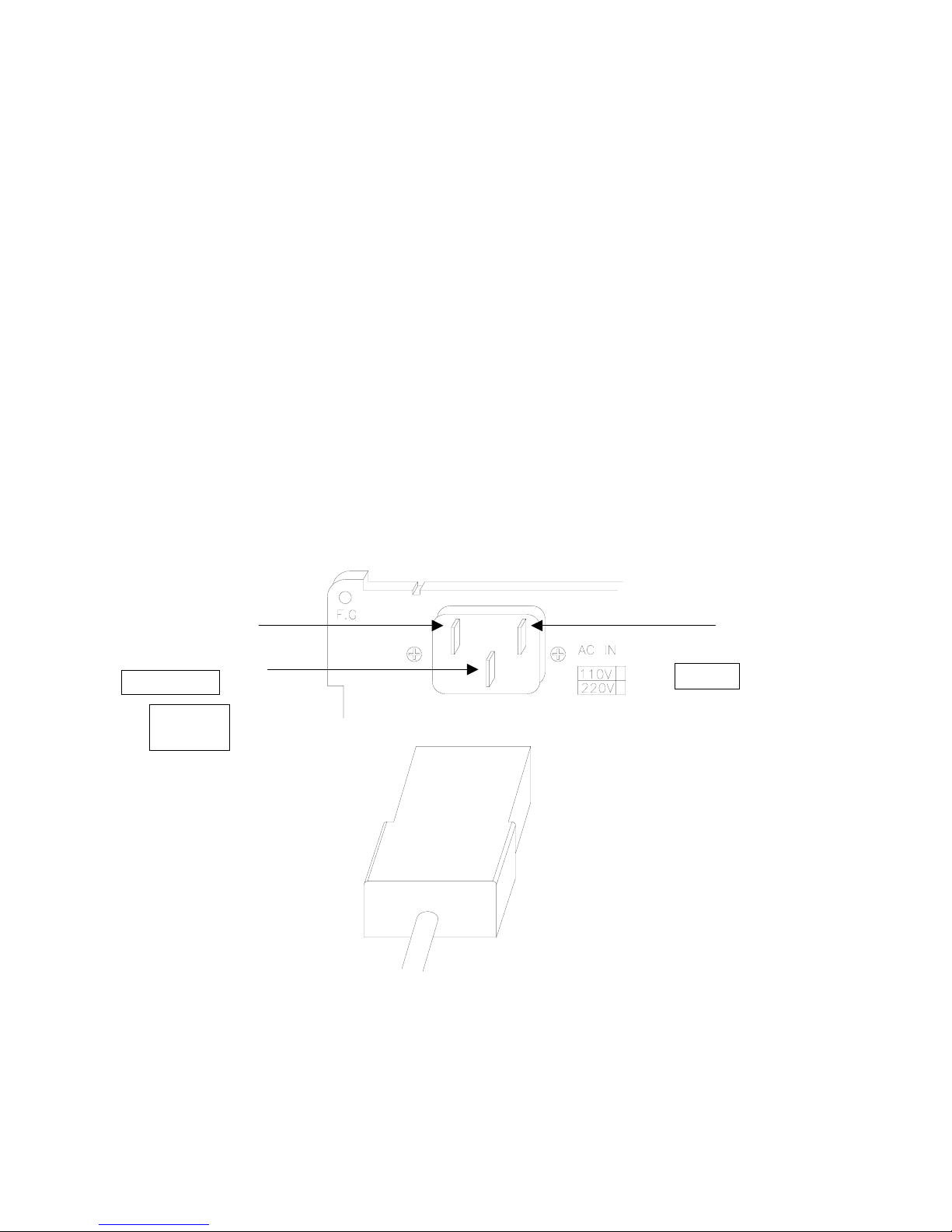
2. AC IN :Available to change AC110/220V with multiple.
Before setting up,please confirm the power voltage.
Please change the connect terminal of 110V/220V after opening the cover
If you need to change. (It was setted with AC220V at the first)
3. FUSE : please use the standard approved .
(FUSE) AC250V, 0.3A (a glass tube with small type)
4. POWER S/W) ON/OFF
It will be safe to use it after 10minuate for a precise measurements
5. DATA OUT (OPTION BOARD) :
Serial Communication.RS422, BCD OUTPUT, Analog Voltage,
Electric Currnet(Analog Out) 0-10V or 4-20mA, Print Out
---------------------------------------------------------------------------------
FINEMECHATRONICS FS8000 10
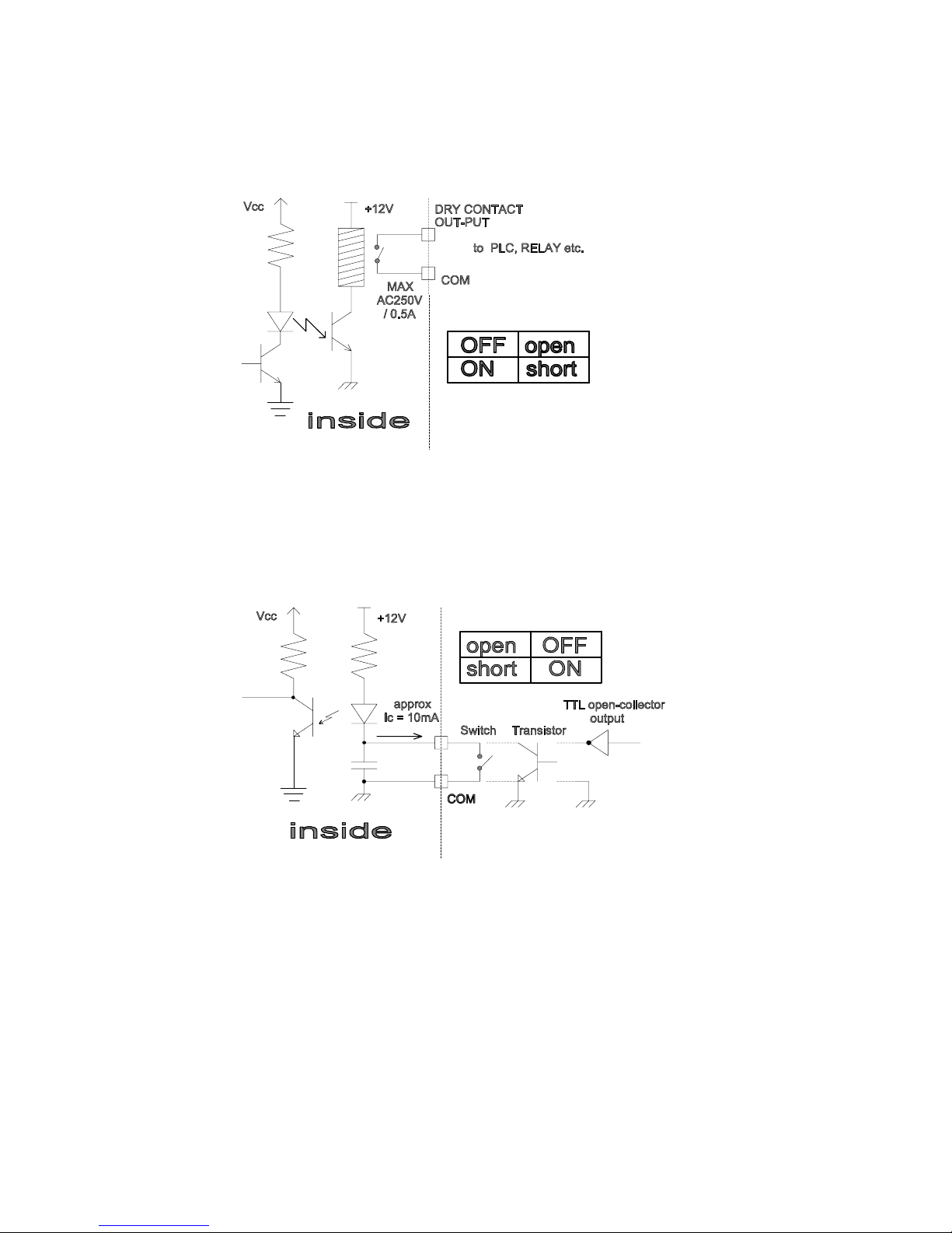
6.OUT-PUT: Connect between COM terminal and OUTPUT terminal
With the earth of no electric power.please use the output data
For a signal only,don`t use it for working.
Max earth capacity : AC250V / 0.5A
7. IN-PUT : This key is to control a equipment from the outside .
The functions of input terminal is to choose it by SETUP F16
Please connect between COM terminal and each input terminal .
Because the power of input terminal was connected with 12V voltage
Fromtheinside.
* An electric current is about10mA.
* Please make the Minium time to input a data with over 50mSEC.
8. RS-232C (25P D-type Female) : (OP-01)
9. Loadcell Connector(N-16)
EX+ (+5V) EX- (-5V) SIG+
SIG- SHIELD
10. ADJUST :DIP Switch for ZERO and SPAN Control
( 1-6No : ZERO , 7-8No : SPAN , 10No : Calibration Lock
Functions of each input terminal is to choose SETUP F16.

---------------------------------------------------------------------------------
FINEMECHATRONICS FS8000 11
1-6.
SPECIFICATION
1. Analog Input & A/D Conversion
2. DIGITAL SECTION
3. GENERAL
4. OPTION
In
p
ut Sensitivit
y
0.2
㎶
/D
ZERO adustment Ran
g
e-4mV ∼42.0mV
Load cell excitation DC 10V
(
±5 V
)
Max In
p
ut volta
g
e32mV
Tem
p
erature Coefficien
t
±20
pp
m / ℃
INPUT Noise ±0.5
㎶
P.P
INPUT Im
p
edance 10 ㏁
(
MAX
)
A/D Converte
r
130,000 Coun
t
Non-Linearit
y
0.005%F.S
MAX.DISPLAY "1000000"
MIN.DIVISION x1, x2, x5, x10, x20, x50
DISPLAY UNIT 7-Se
g
ment, 7di
g
it Hi
g
hl
y
bri
g
ht fluorescent tube
KEY BOARD Numerical Ke
y
and Function Ke
y(
0-9,CLR,SET/CLR
)
Data Back-u
p
APPR.10 YEAR
POWER
AC110 / 220V (
±
10%), 50 / 60Hz, 10VA
PRODUCT WEIGHT NET 2.3k
g
BOX3.3k
g
O
p
eratin
g
Tem
p
erature -10℃∼40℃
O
p
eratin
g
Humidit
y
85%RH MAX
(
Non-Condensin
g)
Ph
y
scal Dimmensions 193.6 x 98 x 166
(
mm
)
OP-01 STANDARD
OP-02 Serial I/F : CURRENT LOOP
OP-03 Parallel I/F : BCD Out
OP-04 Serial I/F : RS422, RS485
OP-05 Analo
g
Out
p
ut : Vout
(
0-10V / 10V-0V
)
OP-06 Analo
g
Out
p
ut : Iout
(
4-20mA / 20-4mA
)
OP-07 Print I/F : CENTRONICS Parallel
OP-10 Parallel I/F : BCD In PART

---------------------------------------------------------------------------------
FINEMECHATRONICS FS8000 12
1-7. The example for the connecting
To external devices
Centronics PARALLEL
BCDOUT
ANALOGOUT 0∼10V
4∼20mA
※Printer : FS-7000D,FS-7000P
FS-7024, FS-7040P
※External DISPLAY : FS-4200, FS-4400
Serialinterface(RS232C,RS422)
EXTERAL
DISPLAY
PRINTER Summing
BOX
P.L.C
Loadcell
Loadcell
Loadcell
Loadcell
ANALOG
RECODER
COMPUTER
---------------------------------------------------------------------------------
FINEMECHATRONICS FS8000 13
CHAPTER 2. INSTALLATION
☞GENERAL RULES
- Avoid sudden Collision,vibration.temperature.water,wind
- Use a stable power supply 110V/220V ±10% 50/60Hz - Set up voltage 220V
(Adjust the power voltage because the choice terminal of power is inside.
- Connect and power off the switch when connecting the external equipments.
- Make ensure to earth Indicator to equipments
- Make ensure to calibrate and set up it for operating.
* PARTS
-POWERCODE :1EA
-FUSE :2EA(PIPETYPE250V0.3ASMALLTYPE)
- LOAD CELL CONNECTOR : 1EA (N16-05)
- OPERATING MANUAL : 1EA
- A Stable Connector for Option installation.
※The connection of power cable
NEUTRAL LIVE
Chassis
Ground

---------------------------------------------------------------------------------
FINEMECHATRONICS FS8000 14
2-1.Out-Dimmension & CUTTING SIZE

---------------------------------------------------------------------------------
FINEMECHATRONICS FS8000 15
2-2. ASSEMBLE DRAWING
---------------------------------------------------------------------------------
FINEMECHATRONICS FS8000 16
2-3.HOW TO CONNECT LOAD CELL
1. STABLE LOAD CELL
The output power of load cell which was used as a weight sensor is 1mV/V ∼3mV/V
▣The output voltage of load cell is not absolute value but relative value.
Ex) if Max weight was loaded to 10kg & 10ton load cell of 3mV/V output,
The Output Voltage is the same as 3mV/V
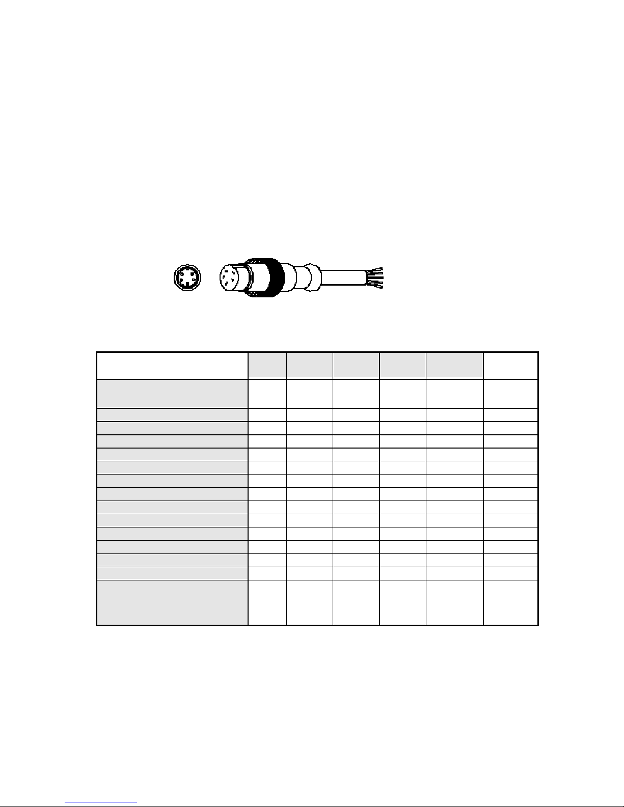
2. Load cell Connector
* Please connect the indicator connector with the wire of load cell
According to the color.
*Possible to connect the load cell of the same kind in parallel up to 8pcs.( Max 300Ω)
3. The wire color of load cell according to a manufacturer.
※Load cell Connector Standard : N16-05
※Because Wire color may be different according to a manufacturer and load cell models.
Please refer for the data sheet of load cell.
1
EXC+
2
EXC-
3
SIG+
4
SIG-
5
SHLD 비고
FINE INDICATOR`S
WIRE COLOR RED WHITE GREEN BLUE SHIELD
BONGSHIN, CAS, TMI, AND RED WHITE GREEN BLUE SHIELD
DAESUNG LOAD CELL RED BLAC
K
WHITE GREEN SHIELD
JUNGSAN RED WHITE GREEN BLAC
K
SHIELD
DAISOCELL RED BLUE GREEN WHITE BLAC
K
DANA RED WHITE GREEN BLUE SHIELD
BLH GREEN BLAC
K
WHITE RED YELLOW
INTERFACE RED BLAC
K
GREEN WHITE SHIELD
KYOWA RED BLAC
K
GREEN WHITE SHLED
P.T. RED BLAC
K
GREEN WHITE SHIELD
SHOWA RED BLUE WHITE BLAC
K
SHIELD
SHINKOH RED BLAC
K
GREEN WHITE SHIELD
TML RED BLAC
K
WHITE GREEN SHIELD
TEAC RED BLUE WHITE BLAC
K
YELLOW
HUNTLEIGH GREEN BLACK RED WHITE SHIELD

---------------------------------------------------------------------------------
FINEMECHATRONICS FS8000 17
2-4. ERROR & A/S
ERROR CAUSE A/S Reference.
Waving a weight
Value.
Load cell demage
Insulation resistance
badness of load cell.
Weighing part error
Checking for Input,
Output of loadcell.
ResistanceValue.
Checking Insulation
Resistance value of
Load cell.
Input resistance
: about 420Ω
Output resistance
: about 350Ω
Insulation
Resistance
: over100MΩ
Load cell demage.
Checking Insulation
Resistance value of
Load cell.
(Normal Max 100MΩor
-OL-appear)
A. Changing a
Weight value,
B. Not return to
ZERO
Disconnceted to
LoadCell.
Confirm a connect of
Load cell
Checking a single wire
Of load cell cable
Weight (-) changed Load cell output
(SIG+,SIG-)changed. Load cell connector ERR-55 occurrence
Disconnect to Load
CellDemage
Load cell demage
Load cell connector
Appear "bAd"
on self-diagnosis
Excess a range of
Zerovalue.
Zero adjustment.
( 5000-15000 )
Load cell demage.
Disconnectto
Indicator.
Load cell demage
Load cell connector
Appear "UL"
(UNDER LOAD)
ZERO adjustment. Zero adjustment.
( 5000-15000 )
Load cell demage
Connection Error
Load cell demage
Load cell connector
Appear "OL"
(OVER LOAD)
Excess Max weight Remove excess weight

---------------------------------------------------------------------------------
FINEMECHATRONICS FS8000 18
CHAPTER 3.CALIBRATION
▣
What is Calibration?
Cablibration is to adjust Max.weight,minium division,decimal point displaied to Indicator
To the actual weight worked by load cell.
☞
It should calibrated certainly when load cell or indicator will be changed.
3-1. ZERO ADJUSTMENT
▣
What is zero adjustment.?
The meaning of ZERO is the fiducial point of weighing operation.
In case a zero value is less than normal operating zero range,
The indicator will be displayed to
"UL".
The other side, it will be displayed to
"bAd".
Then,it will be not operated normally
☞ZERO POINT RANGE
Adjust the value displayed to “test1” closed to 1000 - 20000 (Recommand5000)
( Dip-switch 1-6 )
※ZERO POINT ADJUSTMENT REFERENCE AS FOLLOWS
1. HOW TO ADJUST ZERO POINT
Please turn on while pushing key after turn off
The display was displayed as follows
Push key again,Indicator displays zero value after displaying “test1”
Then,if an zero value was not displayed or displayed with “test1” only
Or not Displayed any number,Turn on the dip-switch(1~6)of the real panel,
Adjust the dip-switch that The number appearing on the display should be closed to 5000.
(Example)
While pushing key + Power turn on -> tESt
While displaying tESt +key,puse key again.
Then this value will be zero value.
tESt

---------------------------------------------------------------------------------
FINEMECHATRONICS FS8000 19
2. How to adjust a dip-switch.(Adjust at the real panel.)
Indicator have the adjust cover on the rear-panel.
Opening the cover,10EA of dip-switch is in this cover.please adjust the zero value
With adjustment key 1∼6No of dip-switch closed bewteen 5000 and 15000
Don`t use the 7.8No of dip-switch when adjusting a zero point.
10No dip-switch is to adjust the calibration (ON: prohibition,OFF: permittion).
(Example)
Question: At present 27300 and dip-switch all condition "ON".
Answer : If 1No of dip-switch was OFF,also the changing range was 980,
The changing range of Each dip-switch is as follows
If 1,2,3,5 dip-switch was OFF,the changed range is 980+1960+3920+15680=22540.
As the resulf of,it will come to 27300-22540=4760 and will result in about 5000.
Small change
← → Wide ran
g
e chan
g
e
1 2 3 4 5 6 a multiple of
zero adjustment changed range
1 ON ON ON ON ON ON 0 0
2 OFF ON ON ON ON ON 1 -980 changed range
3 ON OFF ON ON ON ON 2 -1960 changed range
4 OFF OFF ON ON ON ON 3 -2940 changed range
5 ON ON OFF ON ON ON 4 -3920 changed range
: : : : : : :
62 OFF ON OFF OFF OFF OFF 61 -59780 changed range
63 ON OFF OFF OFF OFF OFF 62 -60760 changed range
64 OFF OFF OFF OFF OFF OFF 63 -61740 changed range
Dip-switch 1 2 3 4 5 6
Changed range 980 1960 3920 7840 15680 31360

---------------------------------------------------------------------------------
FINEMECHATRONICS FS8000 20
3-2. SPAN ADJUSTMENT
▣
what is span adjustment.
Span adjustment is to make the display value from "0" to max.weight consistent to
The actual weight
※Please do OFF NO 10 of dip-switch(Calibration Permittion)
▶How to access the SPAN ADJUSTMENT.
There are 2ways to access the span adjustment
☞
The first way
Turn on the power while pushing
Key.then,the display will be
"tESt"
Then,pushing
Key
again,it will be displayed with
"St. CAL"
Also,pushing SET/CAL on the below right. it will be displayed with "d xx"
("xx" means 01, 02, 05, 10, 20, 50)
예) POWER OFF CONDITIONS
1. While pushing
Key
---------- Display is "tEST"
2. Pushin key again. ---------- Display is "St. CAL"
3. Pushing SET/CAL key ---------- Display is "d 02"
☞
The second way
If pushing SET/CAL key for 3sec,it will be displayed "St. CAL"
"St. CAL" means SETUP & CALIBRATION mode
Table of contents
Popular Accessories manuals by other brands


Vivid
Vivid CLV-401A user manual

PCB Piezotronics
PCB Piezotronics IMI Sensors EX641B61 Installation and operating manual

IFM Electronic
IFM Electronic efector 500 PM2055 operating instructions

Di-soric
Di-soric LHT 9-45 M 10 P3IU-B4 operating instructions

Panlux
Panlux PN71000019 instructions

myfox
myfox TA 4004 user guide


