Fineart FINE 4019 PIXIE PLUS User manual

FINE 4019 PIXIE PLUS
FINE ART Website Product manual Read the user manual before installing or operating this product.
-1-
Contents
P/N: 390712000115 Version: A
1.Technical Feature
2.Photometric diagram
3.Control channel
4.Operation chart for the display panel function
5.Control panel
5.1 Control panel introduction
5.2 Control panel Operation introduction
6.Routine maintenance
7.Safety information
8.Product Connection
8.1 Included items
8.2 Power Connection
8.3 Signal Connection
Attached 1. Wiring diagram
02
03
04
06
10
10
10
11
12
13
13
13
13

Technical feature
FINE 4019 PIXIE PLUS LED
Light source
40W 4 in1 LEDS
Input voltage
100-240V~ 50/60Hz
Input current
9A
Input power
900W
Power factor
PF≥0.98
Beam angle
4°~60°
Initial luminous flux
Small angle: 5834.8 lm, Large angel: 12791 lm
Efficiency
Small angel: 6.9 lm/W, Large angel:15.14 lm/W
Color system
RGBW 4 in 1
Effect
All-optical domain dimming, 65536 grade dimming accuracy
fast strobe 1-25Hz, preset 65 color macro functions, preset
64 effect macro functions
Pan
Pan= 2.11°/step, Pan fine=0.008°
Tilt
Tilt =270°, Tilt=0.94°/step, Tilt fine=0.0037°
Safety protection
Over current, over voltage and overheating protection
Control mode
DMX512/Wireless DMX (optional)
Control channel
21/35/78/97
Work environment
0℃~40℃
Fixture dimension
400×378×500mm
Package dimension
841×515.5×735.5mm
Weight
Net weight: 20kg, Gross weight: 42kg
Package
2pcs/flight case
IP rate
IP 20
1/Technical feature
-2-
Note: The light source is not recommended to replaced by user . Ask qualified maintenance
personnel to replace the light source If any damage or overheat deformation.
2/Photometric diagram
-3-
FINE 4019 PIXIE PLUS (Min Angle)
FINE 4019 PIXIE PLUS (Max Angle)
7m
6m
5m
4m
3m
2m
1m
0m
1m
2m
3m
4m
5m
6m
7m
2
φ0.25
distance( m )
4°(1/2Peak) diameter( m )
7°(1/10Peak) diameter( m ) φ0.51 φ0.76 φ1.01 φ1.27 φ1.52
12
φ0.16
4
φ0.99
φ0.33 φ0.49 φ0.66 φ0.82
6 8 10
0
0
0
R(lux)
G(lux)
B(lux)
W(lux)
Full(lux)0
0
0
0
038332
80773
18834
140278
246490
9582
20193
4709
35069
61622
4259
8975
2093
15586
29500
2396
5048
1177
8767
15406
1533
3231
753
5611
9860
1065
2244
523
3897
6847
7°
(1/10 Peak)
(1/2 Peak)
4°
7m
6m
5m
4m
3m
2m
1m
0m
1m
2m
3m
4m
5m
6m
7m
2
φ2
distance ( m )
35°(1/2Peak)diameter ( m )
60°(1/10Peak)diameter ( m )
φ4φ6φ8φ10 φ12
12
φ1.26
4
φ7.56
φ2.52 φ3.78 φ5.04 φ6.3
6 8 10
0
0
0
R(lux)
G(lux)
B(lux)
W(lux)
Full(lux)0
0
0
0
0972
1962
313
3548
6010
243
491
78
887
1502
108
218
35
394
668
61
123
23
222
376
39
78
13
142
240
27
55
9
99
167
60°
(1/10 Peak)(1/2 Peak)
35°

-4-
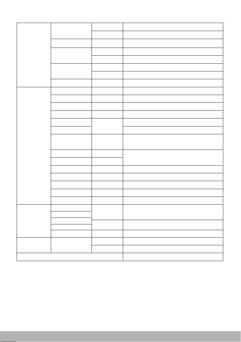
3/Control channel
8 Color temperature 6500K
0-
10 ->255
>9
10 ->255
Color temperature from 8000K to 2700K
Macro color effect
Dimmer 12
12
12
12
0->255 Dimmer Tuning
Dimmer fine 13
13
13
13
0->255 Dimmer Fine
Pan 14
14
14
14
0->255 Pan Tuning
Pan fine 15
15
15
15
0->255 Pan Fine
Tilt 16 16 16 16 0->255 Tilt Tuning
Tilt fine 17 17 17 17 0->255 Tilt Fine
Function 18 18 18 18 0->255 Reserved
No Funtion
Reset 19 19 19 19
0->25 No Function
26->76 ZOOM Reset
77->127 Pan/Tilt Reset
128 ->255 All Reset
Zoom 20 20 20 20 0->255 Spot angle from small to big
Lenses Rotation 21 21 21 21
0->127 0~360°line ratation
9Color temperature 8000K
Macro 10 10
10
10
Strobe 11 11
11
11
0->3 CLOSED
4->103 Pulse Strobe, low->fast, 1Hz-25Hz
104 ->107 OPEN
Strobe, slow->fast, 1Hz-25Hz
OPEN
Random Strobe, slow->fast
108 ->207
208 ->212
213 ->251
252 ->255 OPEN
Rotate clockwise, fast->slow
Stop
Rotate counterclockwise, slow->fast
>190
-
128
>192
-
191
>255
-
193
Specific Stnd RBG RGBW SHAP Value Function
Red 1 1 1 1 0->255 Red Tuning
Red fine 2 2 2 2 0->255 Red Fine
Green 3 3 3 3 0->255 Green Tuning
Green fine 4 4 4 4 0->255 Green Fine
Blue 5
5
5
5
0->255 Blue Tuning
Blue fine 6
6
6
6
0->255 Blue Fine
White 7
7 7 7 0->255 White Tuning
White fine 8
8 8
8
0->255
White Fine
CTO 9
9 9 9
0->3 No Function
5
Color temperature 2700K
Color temperature 3200K
6
Color temperature 4300K
7 Color temperature 5600K
4
-5-
Shape R 25 0->255 shape red dimmer
Shape G26 0->255 shape green dimmer
Shape B
27
0->255 shape blue dimmer
Shape W
28 0->255 shape white dimmer
Shape Dimmer
29
0->255 shape main dimmer
Background
Dimmer
30 0->255 Background
Dimmer
Shape
Transition
31
0->4
no delay for transition
5->255 delay transition duration
100ms ->4s
Shape Offset
32
0->255
Shape Strobe
33
0->3
CLOSED
4->103
104
208
252
-
-
-
>107
108->207
>212
>255
213->251
OPEN
OPEN
OPEN
Pulse Strobe, slow->fast, 1Hz~25Hz
Strobe, slow-> fast, 1 hz~25hz
Random Strobe, slow->fast
Adjustment of shape angle or intensity
Background
Strobe
34
0->3 CLOSED
Background
Select
4->103 Pulse Strobe, slow->fast,1Hz-25Hz
104 ->107 OPEN
108 ->207 Strobe, slow->fast,1Hz-25Hz
208->212 OPEN
213->251 Random Strobe, slow->fast
252->255 OPEN
35
0->8No Funtion
9->23 Background shape Select
24->254 No Select
255 Mirror image enable
Shape Speed 23
0->63 Static shape
64->158 Speed from fast to slow
159->160 Stop
161->255 Speed from slow to fast
Shape Fade
24
0->15
no fade-in/out function
16->255 fade-in/out function and
curve for option
Separate control on single
LED under stnd, RGB, RGBW mode
Shap mode control shap selection manual
Selection
22-
>78
22->
97 22 0->255
Shape

- 6 -
4/Operation chart for the display panel function
Menu Item Options Notes(Default settings in bold print)
Address
Setting
DMX
address
001-512
Specification
Setting
Pan Invert
Reverse DMX
pan control,R->L
Off Normal DMX pan control,L->R
Tilt
Invert
On
On
Reverse DMX
tilt control, D->U
Off
Normal DMX
tilt control,U->D
Pan/Tilt Swap
On
DMX
exchange pan&tilt controlling channel
Off
Normal pan&tilt controlling channel
DMX Mode
Standard
Standard controlling
mode
RGB
RGB controlling
mode
RGBW
SHAP
RGBW
SHAP
controlling
controlling
mode
mode
Exit
Return to the last menu
Pan/Tilt Speed
Fast
Optimize rotation speed
Normal
Medium rotation speed
Slow
Smoothest rotation speed
Pan/Tilt Smooth
000 ~ 007
Optimize pan&tilt rotation speed
Gobo/Color
Normal
Normal speed of gobo&color change
Fast
Optimize speed of gobo&color change
Dimmer Curve
Gm10
Choose different dimmer curve
GM15
Gm20
S
Dimmer Smooth
000 ~ 003
Optimize dimmer smooth
Exit Return to the last menu
Speed
Setting

-7-
Dimmer Fine 000 ~ 255
Pan 000 ~ 255
Pan Fine
000 ~ 255
Tilt
000 ~ 255
Tilt Fine
000 ~ 255
Function control
000 ~ 255
Reset
000 ~ 255
Zoom
000 ~ 255
000 ~ 255
000 ~ 255
000 ~ 255
000 ~ 255
000 ~ 255
000 ~ 255
000 ~ 255
000 ~ 255
000 ~ 255
000 ~ 255
000 ~ 255
000 ~ 255
000 ~ 255
000 ~ 255
000 ~ 255
000 ~ 255
Prism rotation
Exit
Red
000 ~ 255
Red Fine
000 ~ 255
Green
000 ~ 255
Green Fine
000 ~ 255
Blue
000 ~ 255
Blue Fine
000 ~ 255
White
000 ~ 255
White Fine
000 ~ 255
CTC
000 ~ 255
Color Macro
000 ~ 255
Strobe 000 ~ 255
Dimmer 000 ~ 255
Through panel menu
adjust channel values correspondingly
Return to the last menu
Manual
Control
Shape Selection
Shape Speed
Shape Fade
Shape R
Shape G
Shape B
Shape W
Shape Dimmer
Background Dimmer
Shape Transition
Shape Offset
Shape Strobe
Background Strobe
Background Selection
-8-
Calibration
Pan 0000~FFF0
Zero setting and calibration
deviations of every channel
Tilt
0000~FFF0
Zoom
0000~FFF0
Prism rotation
0000~FFF0
Exit
Return to the last menu
DMX VALUES
Receive01~
Receive48
000 ~ 255 Display every DMX channel value received
Exit
Return to the last menu
Password Code01~ Code16
000 ~ 255
Modify restriction of using times and
call in verification code when reloading
Default setup
Exit
Return to the last menu
Personality
Display
Keep
Backlight remains
60s
Shut down backlight if no operation in
60 seconds
Brightness 10%~100%
Adjust display brightness
Display revert On
Display revert
Off
Normal display
Language Chinese
Menu in Chinese
English
Menu in English
Receive Mode
DMX
DMX512
transmission mode
WDMX
Wireless transmission mode
ENET
Ethernet transmission mode
EDMX
Ethernet to DMX transmission mode
Universe 000~255
Art-Net
Ethernet
node setup
IP AddressA 002~010
The defaulted IP should be
IP Address 000~255
IP Address 000~255
2.?.?.? for the product with Art-net
Reserve
Reserve
Reserve
Reserve
IP Address 000~255
Load Config 1 Load Reload previous setup one
Save
Save present setup as setup one
Load Config 2 Load Reload previous setup two
Save Save present setup as setup two
Load Factory
setting
Load Reload default setup
Save Save as default setup
On
Off
Program update
-9-
Personality
Wireless Unlink On Disconnect to wireless emiter
Off Connect to wireless emitter
Fixture Type
F4019
Modify fixture type
Sleep Mode
On Sleep mode enabled
Off Sleep mode disabled
Error display
On Error display enabled
Off Error display disabled
Exit
Return to the last menu
Information
Power On Time
0000~9999
Power on time inquiry(unit:hour)
Lamp On Time
0000~9999
Lamp on time inquiry(unit:hour)
Dimming Time
0000~9999
Dimming time inquiry(unit:hour)
CPU Board Temp
00℃~99℃
Main PCB temperature inquiry
CPU Board Version
Vx.xx
Main PCB version inquiry
0000-7FFF
Device
ID
00000000-FF
FFFFFF
RDM user ID
RDM manufacturer ID
FAN 1 Speed
0000~9999
Display speed of fan ,
(unit:RPM)
FAN 2 Speed
0000~9999
0:P/T Driver Board Temp
00℃~99℃
0:PT board temperature inquiry
0:P/T Driver Board Version
Vx.xx
0:PT board version inquir y
1:LED
Board Temp
00℃~99℃
1:LED
board temperature inquiry
1:LEDBoard Version
Vx.xx
1:LED
board version inquiry
Exit
Exit
Return to the last menu
Return to the last menu
Sensor
Monitor
Normal
Normal function corresponding sensor
work normally
Error
Corresponding sensor works abnormally
Reset All
Systems
Execute Reset the fixture to original settings
Cancel Do not reset the fixture to original settings
Pan
Tilt
Zoom
Prism rotation
Exit
Quit menu and back to “main menu”
Manufacturer ID

Main Menu Interface
001-XXX
IP add setting
main menu
Feature setting
Speed setting
Channel setting
5.2 Control panel Operation introduction
5/The control panel
5.1 Control panel introduction
1.Exit button
2.LCD display
3.Function button(Enter)
4.DMX interface
5.Mains switch
6.Power in
7.Fuse
Figure(5.1-1)
-10-
3. Jog wheel:
Press down the jog wheel: enter an item/save the present value. Holds for a few
more second, it will return to upper menu.
Clockwise rotate: scroll down the page/increase the parameter value.
Counter clockwise rotate: scroll up the page/decrease the parameter value.
Display inverse function: with connection to the supply, press down the “Exit
button” and “Jog Wheel” almost at the same time, the screen display will invert by
180°.
Press the jog wheel for 2s: return to previous menu.
Long Press the jog wheel: return to the main menu.
If there no operation in 2minutes in the menu, which means to return to the original
menu.
4. LED signal indication
DMX512 signal input: The LED light is on and the dot appears on the right side of
the address code.
Fig.5.2-1
Note: Indicate the selected menu items in the menu
interface. If you are sure to enter this menu, please
press the runner to confirm. That is to say, enter the
next menu and continue editing. If this menu option
is not set in the entry address, the menu can be
paged by rotating the runner.
1. Mains switch: It’s power off when turning the mains switch to “O”. And it's power
on when turning the mains switch to “I”.
2. Press button to trigger the built-in battery(note:optional) for startup fixture and
enter the main menu interface for menu operation.

-11-
6/Routine maintenance
This fixture requires routine cleaning. The service life depends on the operating envir-
onment heavily. Please kindly contact GUANGZHOU CHAIYI LIGHT CO., LTD for
more maintenance information not included in this user’s manual.
Notice: Excessive dust, smoke fluid and particulate buildup will degrade performance
and cause over heating or damage to the fixture that is not covered by the warranty.
Warning: Please unplug the fixture before you open any covers.
Cleaning
Optical components should be cleaned carefully and lightly. Coating face is easily
damaged, do not use harmful solvent so as to avoid damage to plastic parts or coating
parts.
Cleaning optical components
1. Switch off the fixture and keep it cool completely, then open the cover.
2. Clean the floats by dust collector or compressed.
3. Use cotton paper without smell or cotton cloth soaked with the water, distilled water
to wipe the granular thing, don't wipe the surface, float things should be blown away
by the pressure gas.
4. Use the cotton cloth or cotton paper without smell soaked with isopropyl alcohol to
remove the smoke and other residues. A commercial glass cleaner may be used,
but residues must be removed with distilled water. Clean with a slow circular motion
from center to edge. Dry with a clean, soft and lint-free cloth or compressed air.
Cleaning fan and air vents
Remove dust from the fans and air vents with a soft brush, cotton paper, vacuum, or
compressed air.
-12-
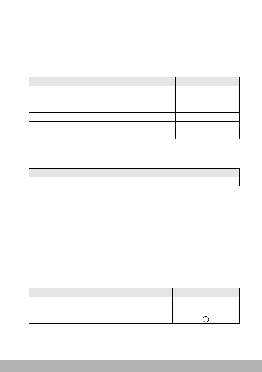
Protection against explosion
Protection screen must be replaced if they have become visible
damaged to such an extent that their effectiveness is impaired.
Keep flammable materials far away from the fixture. Minimum distance
from the flammable materials is 0.5m.
Protection against burning or fire
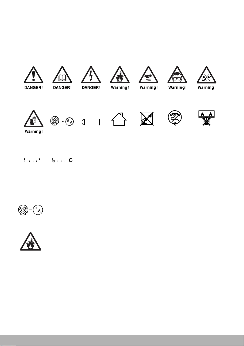
7/Safety information
The following symbols are used to identify important safety information on the product
and in this manual:
c
c
0.5 m
Safety hazard.
Risk of
severe injury
or death.
Refer to manual
before installing,
powering or
servicing.
Hazardous
voltage. Risk of
severe or lethal
electric shock.
Fire
hazard.
Burn hazard.
Hot surface.
Do not touch.
Risk of
eye injury.
Safety glasses
must be worn.
Risk of
hand injury.
Safety gloves
must be worn.
Replace any
cracked
protective
shield.
Minimum
distance from
lighted objects
is 0.5m.
For indoor
use only.
Do not direct
lens to sun
ray or strong
light!
Do not
actuate during
operating.
Rated maximum
ambient
temperature
is 40℃.
The surface’s
temperature
is 62℃.
Do not stare
at the bulb
which is still on.
Luminariesnot
suitablefordirect
mountingonnormally
flammablesurfaces
(suitableonlyfor
mountingon
non-combusible
surfaces)
-1 3 -
8/Product Connection
Table(8.1-1)
Accessories
User manual
Warranty card
Female plug
Signal cable
Safety wire
Fuse
QTY
1
1
1
1
1
2
UNIT
PCS
PCS
PCS
PCS
PCS
PCS
10A 6X30
Power
100-240V~
Fuse
8.1 Included items
FINE 4019 PIXIE PLUS LED is packed with flight case.One single standard flight
case carries two fixtures, Included items listed below (shown as table 8.1-1):
8.2 Power Connection
Power supply and fuses’ type and rating:
Notice: Type Y attachment for power supply connection. Method of attachment of the
cable or cord such that any replacement can only be made by the manufacturer, his
service agent or similarly qualified person.
The person must have the relevant qualification to connect the power supply. The AC
power voltage shall be suitable to the lamp provided with over-loading or creepage
protection.
1. Connecting the equipment to the power supply, do not connect to silicon box
system, or else, it will destroy the equipment.
The fixture is provided with standard 3-pin socket. Please according to table 8.2-2
connect to power supply, Yellow/green line must be earthed. If you still have any
question to the installation, please consultant with the experienced electrician.
2. When power is supplied, put the base switch to the position “I”.
Color
Brown
Blue
Yellow/Green
Wire
Live
Neutral
Earth
Mark
L
N
8.3 Signal Connection
Data linkage for the fixture may be provided by DMX512 connection and wireless
linkage.
Table(8.2-2)
Table(8.2-1)

-1 4 -
3-pin XLR connector
Pin1: GND
Pin2: Signal(-)
Pin3: Signal(+)
Terminator
Terminator specification: a
120Ω plug-in resistor with
rated power of 0.25W,
soldered between pin 2 and
pin 3 at the end of respective
data link.
Fig.(8.3-1)
DMX connection
Note: The signal cable was type X connection.
Type X connection—if the external flexible cable or cord of this fixture is damaged, it
shall be replaced by a special cord or cord exclusively available from the manufact-
urer or his service agent.
3-pin or 5pin XLR connecters are provided for fixture DMX input and output. Pin 1 is
for earthing, pin 2 is for minus signals, and pin 3 is for plus signals. To prevent and
absorb the reflection and interference of the signals, each data link must be ended
by a respective terminator.
1. No more than one signal input or output can occur in one fixture.
2. Don’t split a data link via output ports on the fixture, use a DMX512 signal amplifier instead,
if necessary.
3. Use only shielded-pair cables, and standard microphone cable is not reliable for
long-distance data transfer.
Notice!
If long-distance data transfer occurs, a DMX512 signal amplifier is necessary. The
added amplifier is inserted between the lighting controller and the first fixture on the
basis of a normal data link.
Note: Make sure the fixture vertically upwards when it is placed horizontally, the
safe distance between two adjacent fixtures must be ≥ 500mm.
Fig.(8.3-2)
Terminator
Controller Input Output Input Output
OutputInput
Connect the fixtures with Max.5 pieces. Make sure to insert the “signal in” terminal
in the last connecting fixture. shown in Figure8.3-2.

Attached1: FINE 4019 PIXIE PLUS LED Wiring diagram
Motor drive board
+28V
X light
Y motor
The X axis motor
L
N
Switching
GND
+48V
GND
+28V
Power input:
100-240V
~
50/60 HZ
Fuse 10A/250V
Spin
hall
motor 1
The LED panel
Motor transfer plate
LED Light board
Power fan conver board
The cooling fan
VCC
GND
380V
380V
GND
ACC
DMX signal board
Focusing
motor 2
Focusing
motor 3
Focusing
motor
A rotary
coupling
Y light
coupling
Base of the fan Base of the fan
Display board control board Display
board
LED Light board
driver board
power
supply 1
Switching power
supply 2
The circular
Table of contents
Other Fineart Dj Equipment manuals


