FINEGEAR MODMIX User manual

EXPERIMENTAL CV-CONTROLLED
MIXING CONSOLE WITH
ROUTING & MODULATION
MODMIX
MODMIX
User’s Manual
version 0.1
may 2023

2
MODMIX USER'S MANUAL
Index
introduction PAGE 3
General overview 4
Mixing console 5
Channels 5
—Preamp gain 5
—EQualizer 5
—Aux sends 5
—Panning 5
—Mute/Phones 5
—Volume 5
—Signal LEDs 5
—CV control & LEDs 5
Aux Sends 6
Feedback routing 6
Stereo Returns 6
channel mix level 7
Master output level 7
Phones 7
vu-Meters 7
phantom 7
I/O (back side) 8
—Input 8
—Insert 8
—Effect sends outputs 8
—Effect returns inputs 8
—Master stereo outputs 8
—Phones output 8
—EF inputs 8
CV Modulation PAGE 9
Low Frequency oscillators 9
—LFO speed 9
—LFO symmetry 9
—LFO waveform 9
—LFO sync 9
—CV I/O 9
Envelope followers 10
—Sensitivity 10
—Attack 10
—Decay 10
—Hi-pass 10
—Lo-pass 10
—CV i/O 10
Signal flow diagram 11

3
MODMIX USER'S MANUAL
Welcome to the Modmix User’s
Manual!
If you own this mixing console /
no-input synth, you must be one
who’s partial to the yet unexplored
frontiers of sound, gear and music.
Modmix will be your map with a clear
and simple grid that will allow you to
explore and even lose yourself down
some self-generating rabbit holes.
This document describes Modmix,
the experimental CV-controlled
mixing console with routing and
modulation, as follows:
First, it describes the main features
of the console, with 4 CV-controllable
channels and as many eect sends,
stereo returns and feedback routing
controls ;
Second, power and audio connec-
tions are described;
Third, Modmix's modulation section
of two low frequency oscillators and
two envelope followers, is detailed.
Finally, chaining of multiple consoles
is discussed. A general signal path
and further technical specifications
can be found at the end.
All along the way, you will find tips
and information to help you grasp
control of this unusual machine.
INTRODUCTION

4
MODMIX USER'S MANUAL
❶— 4-Channels controls
❷—Sends, Stereo Returns
& Feedback controls
GENERAL OVERVIEW
❸—Output controls ❹—LFO modulation controls
❺—Envelope follower
modulation controls
LFO 1
EF 2EF 1
LFO 2 MASTER VU-METERCHANNEL 3 CHANNEL 4CHANNEL 1 CHANNEL 2
CHANNEL 3 CHANNEL 4 CHANNEL MIX MASTERCHANNEL 1 CHANNEL 2
ENVELOPE FOLLOWERS
EF 2EF 1
LOW FREQUENCY
OSCILLATORS
LFO 2LFO 1
out
amtout
out
amtin
out
amtout
out
amtin
1
send
2
43
1
send
2
43
1
send
2
43
1
send
2
43
pan vol vol vol volpan pan pan
power
stereo returns
sends
routing
HIGH
GAIN
MID
LOW
PAN
VOLUME
master
phones
aux 1
aux 2
aux 3
aux 4
1
2
3
4
SPEED
symm
wave
sync
route
attack
decay
lo-cut
SENSI
hi-cut
1
2
3
4
clip
ch 1
ch 2
ch 3
ch 4
send 1
send 2
send 3
send 4
clipsig clipsig clipsig clipsig
clip
EXPERIMENTAL CV-CONTROLLED
MIXING CONSOLE WITH
ROUTING & MODULATION
MODMIX
MODMIX
10
-
8
10
-
8
10
-
8
10
-
8
10
-
8
10
-
8
40
-
8
10
-
8
-
8
10
10
-
8
10
-
8
10
-
8
-
8
10
10
-
8
10
-
8
L
R
L R L R L R
0
-
8
0
-
8
0
-
8
0
-
8
0
-
8
0
-
8
0
-
8
0
-
8
0
-
8
0
-
8
0
-
8
0
-
8
0
-
8
0
-
8
0
-
8
0
-
8
-10 10 -10 10 -10 10 -10 10
-10
10
-10
10
-10
10
-10
10
-10 10 -10 10 -10 10 -10 10
-
8
40
-
8
40 40
-
8
40
-
8
20 10 20 10
200 18 200 18
010010
0500 ms0500 ms
060 ms060 ms
010
0%
50%
100%0%
50%
100%
- +
- +
- +- +
010
phantomoff
onoff
onoff
phonesmaster phonesmaster phonesmaster phonesmaster
20 40 60 80
20
10 73
32
1
+
VU
100
1
-
0
0
5
20 40 60 80
20
10 73
32
1
+
VU
100
1
-
0
0
5

5
MODMIX USER'S MANUAL
Mixing console
CHANNELS
Modmix's 4 channels are simple and
transparent, providing a clean vehicle
for all kinds of experimentation.
❶—Preamp gain
This input gain knob is used to trim/
amplify the incoming signal.
❷—EQualizer
This is a 3-band-equalizer with a very
simple and transparent circuit. The
frequency ranges of the three bands
are:
• 60 Hz
• 300 Hz -1.9 Hz
• 12 K Hz.
This, adding to the +/-10 dB gain range
gives a very pleasant sounding EQ.
❸—Aux sends
These knobs are used to send more
or less of the channel’s signal to one
of the four eect send buses (called
1, 2, 3 and 4) included in Modmix. The
signal is taken aer the volume knob
(post-volume).
❹—Panning
The pan knob controls the panoramic
(le/right) position of channel’s
signal.
^
The knob is in the middle position: the
signal is sent equally to both the left
and right channels;
^
All the way to the left (L): the signal is
only sent to the left channel;
^All the way to the right (R): the signal is
only sent to the right channel.
❺—Mute/Phones
This switch mutes the signal before
the volume knob (so the aux sends are
implicitly muted too). It then reroutes
the signal to the phones output.
L
There are jumpers inside the unit to
change this behavior and only route
the signal to the phones output,
without also muting the channel.
❻—Volume
This knob controls the level of the
signal passing through the channel.
It has a 10 dB gain range at the top
and a 0 dB indicator.
❼—Signal LEDs
These LEDs allow you to monitor your
signal.
^
The green "signal present" LED is lit if a
signal above -20 dB is present.
^
The red "clipping" LED turns on if the
signal goes above 0 dB.
❽—CV control & LEDs
For each channel, use these CV-inputs
to control the aux-sends, panning,
and volume.
Bi-colour LEDs indicate the param-
eter being controlled: green means
positive voltage, while red is negative.
CHANNEL 1
CHANNEL 1
1
send
2
43
pan vol
HIGH
GAIN
MID
LOW
PAN
VOLUME
aux 1
aux 2
aux 3
aux 4
route
clipsig
10
-
8
L
R
0
-
8
0
-
8
0
-
8
0
-
8
-10 10
-10 10
-10 10
-
8
40
phonesmaster
Figure 1: CHANNeL 1 MAiN CONTrOLS

6
MODMIX USER'S MANUAL
Mixing console
SENDS
❶—
These knobs control the gain of
eect send buses from o to +10 dB.
❷—Eect sends clipping LEDs: If
one of the signals sent to the eect
send outputs is clipping, the respec-
tive LED will turn on.
L
In this case, lower either the general
effect send gain (❶) or one of the
individual channel's send levels, or
one of the channels' volume (Fig. 1,
page 5, items ❸, ❻).
FEEDBACK ROUTING
❸—
These switches route their corre-
sponding send bus signal to the respec-
tive channel (send 1 is routed to channel
1, send 2 to channel 2, etc.).
L
Use these switches to apply no-input
mixer techniques, and turn the mixer
(or a part of it) into a synth.
STEREO RETURNS
❹—
These knobs control the gain of the
signal that comes back from the eects
connected to the mixer, before being
routed into the master bus.
❺—Eect return clipping LEDs: If one
of the eect return signals is clipping
before being mixed to the master bus,
the respective LED will light.
L
If this occurs, lower the general effect
return gain (
❹
) or alter the settings
of the effect so as to avoid clipping.
stereo returns
sends
routing
1
2
3
4
1
2
3
4
clip
ch 1
ch 2
ch 3
ch 4
send 1
send 2
send 3
send 4
clip
10
-
8
-
8
10
10
-
8
10
-
8
10
-
8
-
8
10
10
-
8
10
-
8
Figure 1: Aux-SeNdS, FeedbACk & STereO reTurN CONTrOLS, wiTH
THeir reSpeCTive iNdiCATOr LedS
7
MODMIX USER'S MANUAL
Mixing console
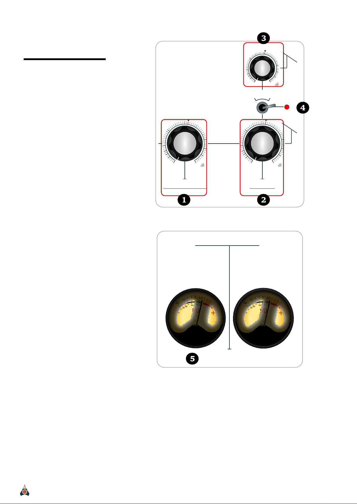
CHANNEL MIX VOLUME
❶—This knob controls the level of
the 4 mixed channels.
MASTER OUTPUT VOLUME
❷—This knob controls the master
output level, i.e. channel mix and
returns.
PHONES
❸—This knob controls the head-
phones amplifier’s gain.
PHANTOM
❹—
Use this switch to toggle the 48V
phantom power for the microphone
inputs.
VU-METERS
❺—
These analog vuMeters monitor
the master output volume.
CHANNEL MIX MASTER
master
phones
10
-
8
10
-
8
40
-
8
phantomoff
Figure 1: OuTpuT CONTrOLS
MASTER VU-METER
20 40 60 80
20
10 73
32
1
+
VU
100
1
-
0
0
5
20 40 60 80
20
10 73
32
1
+
VU
100
1
-
0
0
5
L R
Figure 2: ANALOg vu MeTer
8
MODMIX USER'S MANUAL
Mixing console
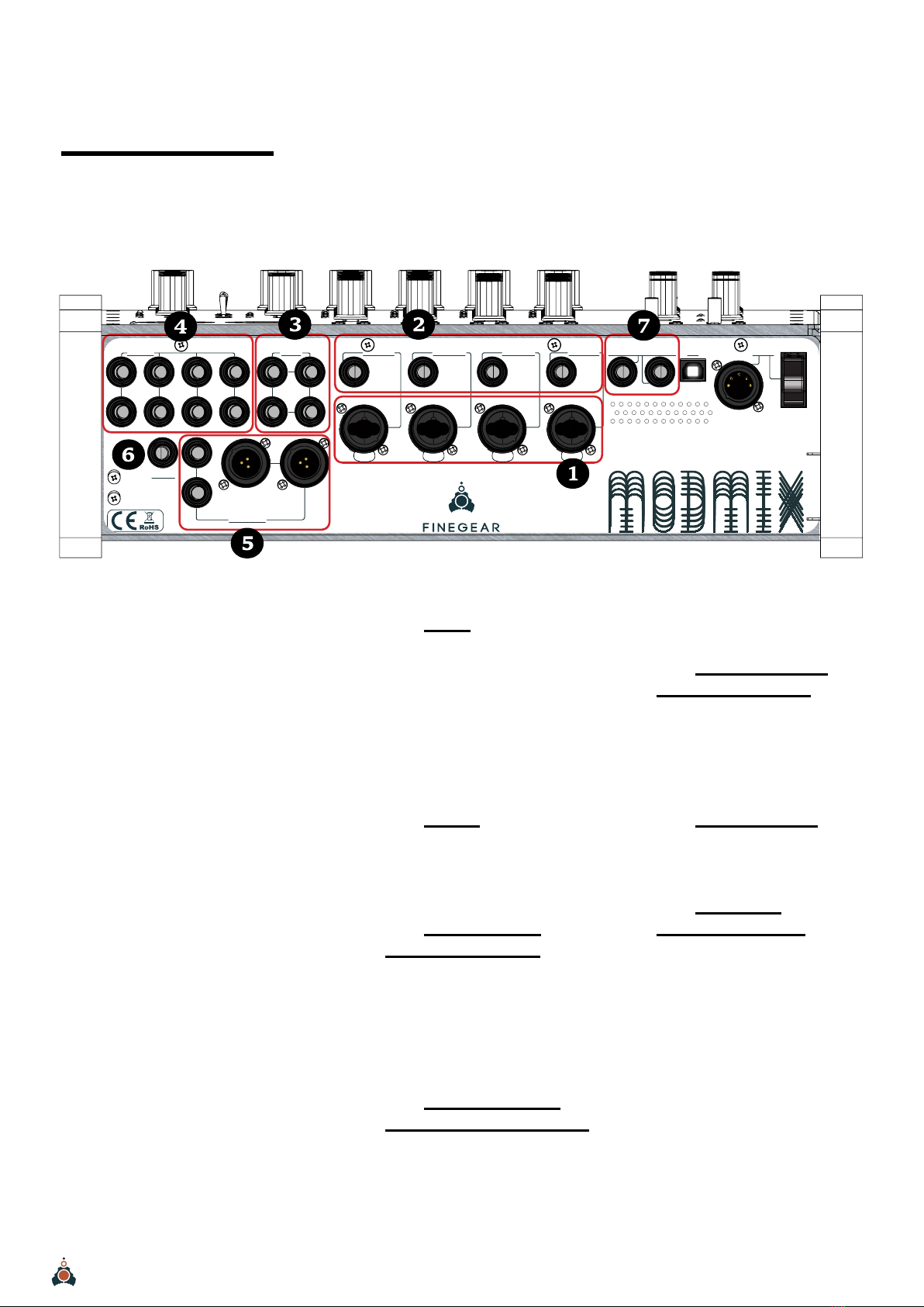
I/O (BACK SIDE)
Modmix's 4 channels accept a variety
of connections to instruments, micro-
phones and external eects. It has
4 eect send outputs and as many
stereo returns inputs.
volorum aut .
❺—Master stereo
balanced outputs
These are individual (le and right),
balanced outputs for the master
buses, in XLR and ¼” jack versions.
❻—Phones output
Headphone amplifier output jack.
❼—Envelope
followers inputs
Inputs for each of the two envelope
followers.
L
If no cables are connected to these
jacks, EF1’s pre-patched input will be
the signal coming from Channel 1. EF2
will receive the signal from Channel 2.
❶—Input
This is the channel’s balanced input:
connect a line instrument or micro-
phone here. This input accepts
both XLR and ¼” jack connec-
tors. Unbalanced jacks can also be
connected.
❷—Insert
The ¼” jack allows the connection
of an external eect to the channel.
❸—Effect sends
balanced outputs
Eect sends buses are output through
these balanced jacks. These outputs
should be connected to the inputs of
an external eects unit.
❹—Effect returns
balanced stereo inputs
The output signal from the external
eects (❸) is returned into the mixing
console through these balanced input
jacks. Luptatibusa pla sam, sequi
ENVELOPE FOLLOWERSCHANNEL 1CHANNEL 2CHANNEL 3
CHANNEL 4
MASTER OUT
PHONES
SENDS
RETURNS
USB
ef 1
off / on
POWER
ef 2
input
rightleft
left
right
input input input
insert11L2L3L4L
1R2R3R4R 2
3
4
insert insert insert
MODMIX
MODMIX
Figure 1: bACkSide iNpuTS ANd OuTpuTS

9
MODMIX USER'S MANUAL
CV Modulation
This CV-modulation section is unusual
in a mixing console, but it is here to
provide sound generation and manip-
ulation opportunities. These two LFOs
are MIDI-syncable and identical...until
they shapeshi.
LOW FREQUENCY
OSCILLATORS
❶—LFO speed
This knob sets the speed of the LFO.
Alternatively, in MIDI sync mode, it
sets the tempo division, ranging from
Tempo × 32 to Tempo ÷ 32.
❷—LFO symmetry
Sets the symmetry of the waveform.
❸—LFO waveform
Selects the output waveform between
sine, triangle and square.
❹—LFO sync
This switch toggles syncing the LFO
to the USB MIDI input in the back of
the unit (see Fig 1, page 8).
❺—LFO AMOUNT
This knob with a mid-detent sets a
bipolar amount for the LFO and the
inverted LFO outputs:
^middle: the amount is zero,
^right: the amount is positive
^left: the amount is inverted/negative.
❻—Speed CV INPUT
Input for modulating the speed of the
LFO using a CV (3.5 mm jack).
❼—Speed CV
modulation indicator
Bi-colour LED providing visual feed-
back of the CV input’s (❻) value.
❽—LFO Output
Outputs the LFO (3.5 mm jack).
❾—Inverted LFO
Output
Outputs the inverted LFO (3.5 mm
jack).
❿—LFO output
indicator
Bi-colour LED providing visual feed-
back of the LFO’s output value. They
indicate bi-polar CV values:
^RED = negative CV voltages
^GREEN = positive voltages.
LFO 1 LFO 2
outout
amtin
outout
amtin
- +- +
Figure 2: LFO Cv-CONTrOLS
LFO 1
SPEED
symm
wave
sync
0%
50%
100%
010
onoff
Figure 1: LFO MAiN-CONTrOLS
SPEED SYMM SYNC
-1
WAVEFORM
LFO
SPEED
CV INPUT
LFO
OUT 1
LFO
OUT 2
INVerted
LFO
OUT
LFO
AMOUNT
+-
LFO OUT
W/ AMT
Figure 4: eNveLOpe FOLLOwer SigNAL FLOw
0% 50% 100%
Figure 3: LFO SyMMeTry wAveFOrM SHApeS
10
MODMIX USER'S MANUAL
CV Modulation
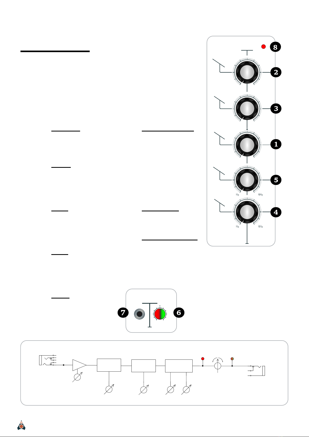
ENVELOPE FOLLOWERS
There are two envelope followers in a
Modmix unit, allowing you to control
the shape of the signal coming through
the console. If no audio input is used,
channels 1 and 2 provide the default
signals.
❶—Sensitivity
Sets the envelope follower’s sensi-
tivity to the input signal.
❷—Attack
Sets the attack time of the enve-
lope follower, in a range of 5 to 60
miliseconds.
❸—Decay
Sets the decay time of the enve-
lope follower, in a range of 20 to 500
miliseconds.
❹—Hi-cut
Sets the cuto frequency for the
Hi-Cut filter found at the input of the
envelope follower.
❺—lo-cut
Sets the cuto frequency for the
Lo-Cut filter found at the input of the
envelope follower, aer the Hi-Cut.
❻—EF Output amount
This knob has a mid-detent and sets
a bipolar voltage amount for the EF
and inverted EF outputs:
^middle: the amount is zero,
^right: the amount is positive
^left: the amount is inverted/negative.
^RED = negative CV voltages
^GREEN = positive voltages
❼—EF CV output
Outputs the envelope follower.
❽—EF output indicator
Bi-colour LED providing visual feed-
back of the EF’s output value. They
indicate bi-polar CV values:
^RED = negative CV voltages
^GREEN = positive voltages
EF 2EF 1
amtout amtout
- +
- +
Figure 2: eNveLOpe FOLLOwer Cv-CONTrOLS
EF 1
attack
decay
lo-cut
SENSI
hi-cut
20 10
200 18
010
0500 ms
060 ms
Figure 1: eNveLOpe FOLLOwer MAiN CONTrOLS
low pass
SENSITIVITY
AUDIO
INPUT
low pass
AT TACK DECAY
ENVELOPE
FOLLOWER EF
CV OUT
EF
AMOUNT
EF OUT
W/ AMT
EF
OUT
+-
high pass
high pass
Figure 3: eNveLOpe FOLLOwer SigNAL FLOw

11
MODMIX USER'S MANUAL
SIGNAL FLOW DIAGRAM
mic
feedback
feedback routing
to channels
channel 1 output
channel 1 send/ feedback/ return
send/ feedback/ return
output
volume
line
preamp
gain
insert
3-band eq
volume
cv
send 1
level
RETURN 1
level
RETURN 1
input
RETURN 2
level
RETURN 3
level
RETURN 4
level
send 1
out
send 1
output
RETURN 2
input
send 2
output
RETURN 3
input
send 3
output
RETURN 4
input
send 4
output
21l r
l r l r
3 4
send 1
cv
send 2
level
send 2
cv
send 3
cv
send 3
level
send 4
cv
send 4
level
pan
cv
mute
CHANNEL
MIX
CHANNEL
MIX
PHONES
phones
output
master
output
right
master
output
lef t
feedback routing
SEND
master phones
pan
send 2
out
feedback routing
send 3
out
feedback routing
send 4
out
feedback routing
2
1
3
4
clip
signal
MASTER
volume
pad
phantom
+48 V
pan cv
LED
volume cv
LED send 1 cv
LED
send 2 cv
LED
send 3 cv
LED
send 4 cv
LED
clip
clip
clip
clip
clip
clip
clip
clip
2
3
4

MODMIX
User’s manual
written by Cristian Kreindler
Founder & RD
Finegear Evolving Instruments SRL
more info at finegear.net
layout & design by
om*objetmarginal
Cluj-Napoca, Romania
©February 2023
Table of contents
Other FINEGEAR Music Mixer manuals


