Finest 226 User manual
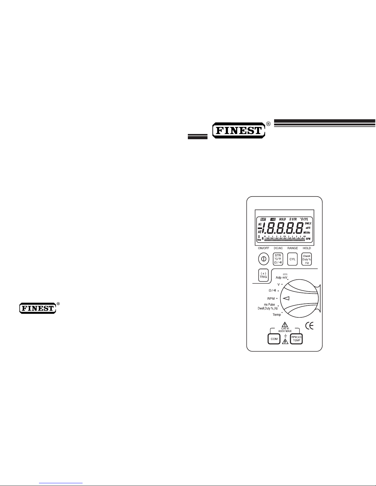
226
228
AUTOMOTIVE MULTIMETER
USER’S MANUAL
FINE INSTRUMENTS CORPORATION
- TEL: (82-31) 470-8888 - FAX: (82-31) 470-8887
© Copyright 2003 Fine Instruments Corp. All right reserved.
Specifications subject to change without notice.
Litho in Korea.
a world leader in test & measurement
Room # 601, DAEWOO TECHNOPIA, 768-1, WONSI-DONG, DANWON-GU,
ANSAN-SI, GYEONGGI-DO, SOUTH KOREA
SOURCES LIKE SMALL HAND-HELD RADIO
TRANSCEIVERS, FIXED STATION RADIO AND
TELEVISION TRANSMITTERS, VEHICLE RADIO
TRANSMITTERS AND CELLULAR PHONES
GENERATE ELECTROMAGNETIC RADIATION
THAT MAY INDUCE VOLTAGES IN THE TEST
LEADS OF THE MULTIMETER. IN SUCH CASES
THE ACCURACY OF THE MULTIMETER CAN-
NOT BE GUARANTEED DUE TO PHYSICAL
REASONS.
DO NOT FORGET INSTALL THE EXTRA
BATTERY COVER AFTER REPLACING THE
BATTERY FOR PROTECTION.
WARNING!
1
Measurement Limits:
DC Voltage : 0.1 mV to 600 V
AC Voltage : 1 mV to 600 V
RPM : 30 to 9000 RPM
Resistance : 0 to 40 M
Frequency : 0.5 Hz to 200 kHz [ 226 only ]
Pulse Width : 0.5 to 1999.9 mS
Dwell : 0 ° to 356.4 °
% Duty Cycle : 0 to 99.9 %
Temperature : -40 to +2,498 [ 228 only ]
( -40 to +1,370 )
Continuity check : Beep sounds at approx. < 100 in the 4 K
range
WARNING!
READ “ SAFETY CONSIDERATIONS” BEFORE USING THIS
METER.

This instrument is handheld and battery operated. It is designed
and tested according to IEC Publication 1010-1 (EN61010-1),
(Overvoltage Category III), the EMC Directive (EN 50081-1 and
EN 50082-1), UL 1244 & UL 201 and other safety standards (see “
Specifications”).
This User’s Manual tells you how to use this instrument. You may
also need a manual that provides technical information for the
vehicle you plan to test. The most important information resources
are the vehicle’s service repair manuals.
This User’s Manual should be used as a guide to get you started in
troubleshooting. Your real learning can best be accomplished
through experiences.
Features:
¥Accurate mS-Pulse Width function to test on-time of fuel
injectors
¥High-speed 41 segment analog bar graph updated 20
times/second — as fast as the eye can follow
¥Accurate automotive electronics test and advanced
measurements with dc/ac Volts, Resistance.....
¥Direct reading of Dwell without using Duty Cycle to Dwell
conversion chart when testing electronic fuel injection, feedback
carburetors, and ignition systems
¥RPM measurement for automotive engines with 1 to 8 Cylinders
using the Inductive Pickup
1. INTRODUCTION
1. Introduction 3
2. International Symbols 4
3. Explanation of Controls and Indicators 8
4. Power - on options 17
5. Basic electrical tests and measurements 18
6. Basic automotive diagnostic testing 37
Battery tests 37
Voltage drop tests 41
Starter motor tests 46
Charging system tests 48
Ignition system tests 51
Summary of automotive electrical system tests 57
7. Maintenance and replaceable parts 59
8. Specifications 61
Electrical specifications 61
General specifications 63
CONTENTS
2 3

■Keep cigarettes, sparks, and open flame away from battery at all
times.
■Keep yourself clear of all moving or hot engine parts.
■Always avoid working alone.
■Do not try to measure any voltage that exceeds 600 V dc or ac
rms.
■Voltages above 25 V dc or ac rms may constitute a serious
shock hazard.
■Do not attempt to use this instrument if either the instrument or
the test leads have been damaged.
■Use a clamp current probe.
■Avoid electrical shock: do not touch the test leads, tips or the
circuit being tested.
■Select the proper function and range for the measurement.
Do not try voltage measurements that may exceed the ratings
marked on the input limit for switch or terminal.
■Disconnect the live test lead before disconnecting the common
test lead.
International symbols
Dangerous Voltage ( Risk of electric shock)
Alternating Current (ac)
Direct Current (dc)
Either dc or ac
¥This instrument exercises 4 step adjustable +/- triggers on 1 to 8
Cylinders, motorcycles and conventional engines for accurate
measurements of RPM, Dwell, Duty-cycle, and mS-Pulse Width
of injectors.
¥Accurate non-automotive Frequency measurements with 20000
count on the high resolution 4000 count display [ 226 Only ]
¥Temperature measurement up to 2,498 ˚F (or 1,370 ˚C) for
catalytic converters, fan switch on/off,.... [ 228 Only ]
¥Non-TRMS
Electricity is dangerous and can cause injury and death. Always
treat it with the greatest of respect and care. If you are not quite
sure how to proceed, stop and take advice from a qualified person.
■Exhaust gas contains carbon monoxide which is odorless, causes
slower reaction time, and can lead to serious injury. When testing
vehicle with engine running, testing should be always done in a
well-ventilated area or route exhaust gas outside.
■Set the parking brake and block the wheels before testing or
repairing the vehicle, unless instructed otherwise. It is
especially important to block the wheels on front-wheel drive
vehicles: The parking brake does not hold the drive wheels.
The ignition or fuel system must always be disabled when
performing starting system tests.
■Always wear an eye shield when working near batteries.
■Do not smoke or allow open flames or sparks in the work area.
Gasoline fumes and gases produced by batteries are highly
explosive.
2. SAFETY CONSIDERATIONS
4 5

Ground (maximum permitted voltage between terminal
and ground)
Caution! Refer to the user’s manual before using this
Meter.
Double Insulation (Protection Class ll)
WARNING!
OBSERVE ALL SAFETY PRECAUTIONS WHEN MEASURING
HIGH VOLTAGES. TURN OFF POWER TO THE CIRCUIT
UNDER TEST, SET THIS METER TO THE DESIRED FUNCTION
AND RANGE, CONNECT THE TEST LEADS TO THIS METER
AND THEN TO THE CIRCUIT UNDER TEST. REAPPLY
POWER. IF AN ERRONEOUS READING IS OBSERVED,
DISCONNECT POWER IMMEDIATELY AND RECHECK ALL
SETTINGS AND CONNECTIONS.
Don’t Forget!
•To maintain accuracy of the Meter, replace the discharged
battery immediately when the Low-Battery symbols, ,
appears on the display of the Meter.
•Keep the Meter away from spark plug or coil wires to avoid
measuring error from external interference.
•Remove the test leads from the test points before changing
functions to avoid damaging the Meter when testing voltage.
•Do not exceed the input limits shown in the table below:
FUNCTION (+) TERMINAL MAXIMUM INPUT
VΩRPM 600 V
VΩRPM 600 V
* Ω
**Hz
RPM
Duty Cycle (%) VΩRPM 500 V DC/AC
Dwell
***Temperature VΩRPM 60 V DC or 24 V AC RMS
*Ohms can be measured only in a nonpowered circuit.
* * Hz(non-automotive Frequency measurement) function is available in Model: 226
Only.
* * * Temperature mode is available in Model: 228 Only.
V
V
mV
6 7
VΩRPM 600 V
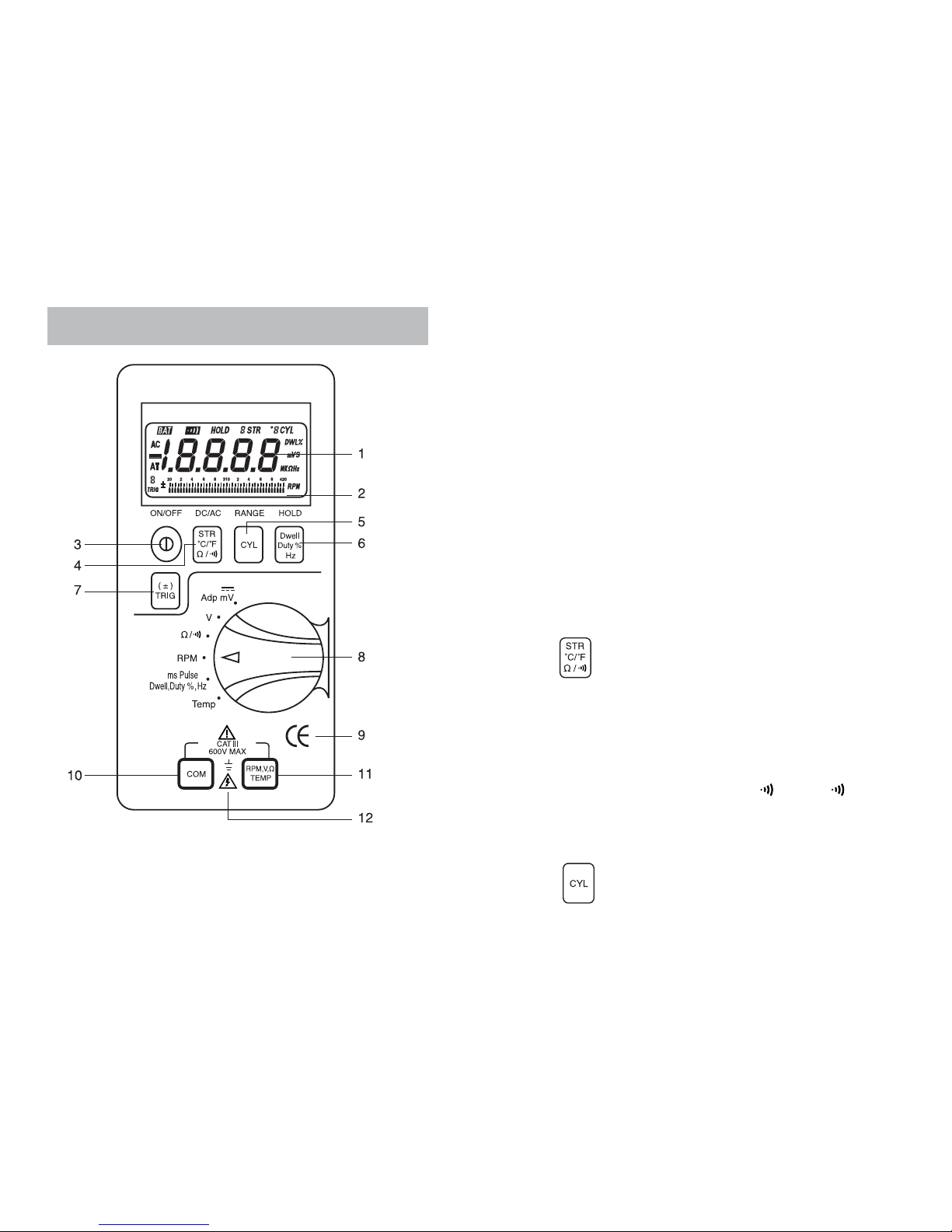
1 – DIGITAL DISPLAY. Digital readings are displayed on a
4000 count display with polarity indication and automatic
decimal point placement. When this Meter is turned on, all
display segments and symbols appear briefly during a
selftest. The display updates four times per second.
2 – ANALOG BAR GRAPH. The bar graph provides an analog
representation of readings and updates 20 times per second.
The 2 x 41 segment bar graph illuminates from left to right as
the input increases. The bargraph is easier to read when the
data causes the digital display to rapidly change. It is also
useful for trend setting or directional data.
The bar graph is not displayed when measuring RPM, Pulse
Width, Dwell, Duty cycle and Frequency.
3 – ON/OFF . Selects meter’s power ON or power OFF.
4 – DC/AC. Toggle between volts dc and ac;
Toggles between 2-Cycle engines (or DIS* 4-
Cycle engines) and 4-Cycle engines when the
Meter is in the RPM mode (The change in the
number of Cycles is indicated by the number
preceding STR on the LCD display);
Toggles between ˚C and ˚F in the temperature
mode [ 228 Only ];
Toggles between Ωand in the Ω/ function.
* DIS = Distributorless Ignition System
5 – RANGE. Press the RANGE button to select the Manual
Range mode and turn off the “AT” symbol. (The
Meter remains in the range it was in when manual
ranging was selected.)
3. EXPLANATION OF CONTROLS AND INDICATORS
8 9
* * 11 RPM, V, Ω[ 226 Only ]
Hz
**

To exit the Manual Range mode and return to
autoranging, press and hold down the RANGE
button for 2 seconds. The “AT” symbol turns back
on.
When the Meter is in the Dwell mode, press the
CYL (RANGE) button to toggle between
1,2,3,4,5,6,8 cylinder engines. The change in the
number of cylinders is indicated by the number
preceding CYL on the LCD display.
6 – HOLD ( Fix Hold
TM
). Automatically captures a stable
reading, beeps to acknowledge, and holds it on
the LCD.
When the Meter is in the mS-Pulse mode, press
this button to measure Dwell.
To measure Duty cycle (or Duty factor) in percent,
press this button again; % is displayed on the
LCD.
To measure automotive Frequency (Hz), press
this button again.
You can step through mS-Pulse, Dwell, Duty
cycle (%) and automotive Frequency (Hz)
measurement mode by pressing this button.
Press any other button to exit these modes.
10 11
7 – Toggles between a Negative (–) and Positive (+)
Trigger Slope when the Meter is in the Pulse
Width or Duty cycle (%) mode; Press this button
down for 2 seconds to toggle between a negative
(–) and positive (+) trigger slope. The change in
the trigger slope is indicated by a + or - shown at
the lower left corner of the display. The Meter
defaults to a – trigger slope. Once the trigger
slope is selected, press this button repeatedly to
adjust trigger level if the Meter reading is too high
or unstable.
•The Trigger Level has Four steps and is different for each
function combination.
Press this button to move one step at a time for selecting a
suitable trigger level. The change in the number of step is
indicated by the number above the “TRIG” symbol at the lower
left corner of the LCD.
•The step number on the LCD is a good indication of the
Trigger Level.
FUNCTION TRIGGER LEVEL
STEP RPM, mS-Pulse, Dwell, Duty %
3+8 V
2+6.25 V
1+3.2 V
0+1.6 V

8 – ROTARY SWITCH. Describes functions that are selected by
setting the rotary selector switch.
Adp mV Millivolts dc or adaptor (current probe)
VVolts dc/ac
Ω/Resistance/Continuity test
RPM RPM measurement on 2 or 4 stroke engines
using the Inductive Pickup on a spark plug wire
mS-Pulse Pulse Width, Dwell, Duty cycle (%) or automotive
Hz(Automotive Hz) measurement
Hz Frequency (Non-automotive Hz) measurement
[ 226 Only ]
TEMP Temperature [ 228 Only ]
9 – CE. This Meter is CE-marking certificated.
10 – COM (Common Terminal). The black test lead is plugged
into this terminal for all measurements. When measuring
temperature, a thermocouple adapter is plugged into this
terminal.
11 – . The red test lead is plugged into this terminal
for all measurements. When measuring
temperature, a thermocouple adapter is
plugged into this terminal.
Dwell,
Duty%,
Hz
RPM, V, Ω
TEMP
[ 228 Only ]
RPM, V, Ω
Hz
[ 226 Only ]
12 – The maximum voltage that the Meter can
measure is 600 V dc or ac rms.
13 – AC . Displayed when AC measurement function is selected.
14 – (Negative Polarity) . Automatically indicate negative
inputs.
15 – AT . DIsplayed when the Auto Range mode is selected.
16 –
88
. Displayed when a certain step of 4 trigger level steps is
selected in the RPM, Pulse Width, Dwell or Duty % mode.
17 – TRIG . Displayed when a – or + trigger slope is selected
while the Meter is in the RPM, Pulse Width, Dwell or Duty %
mode. The Meter defaults or a – (negative) trigger slope.
12 13
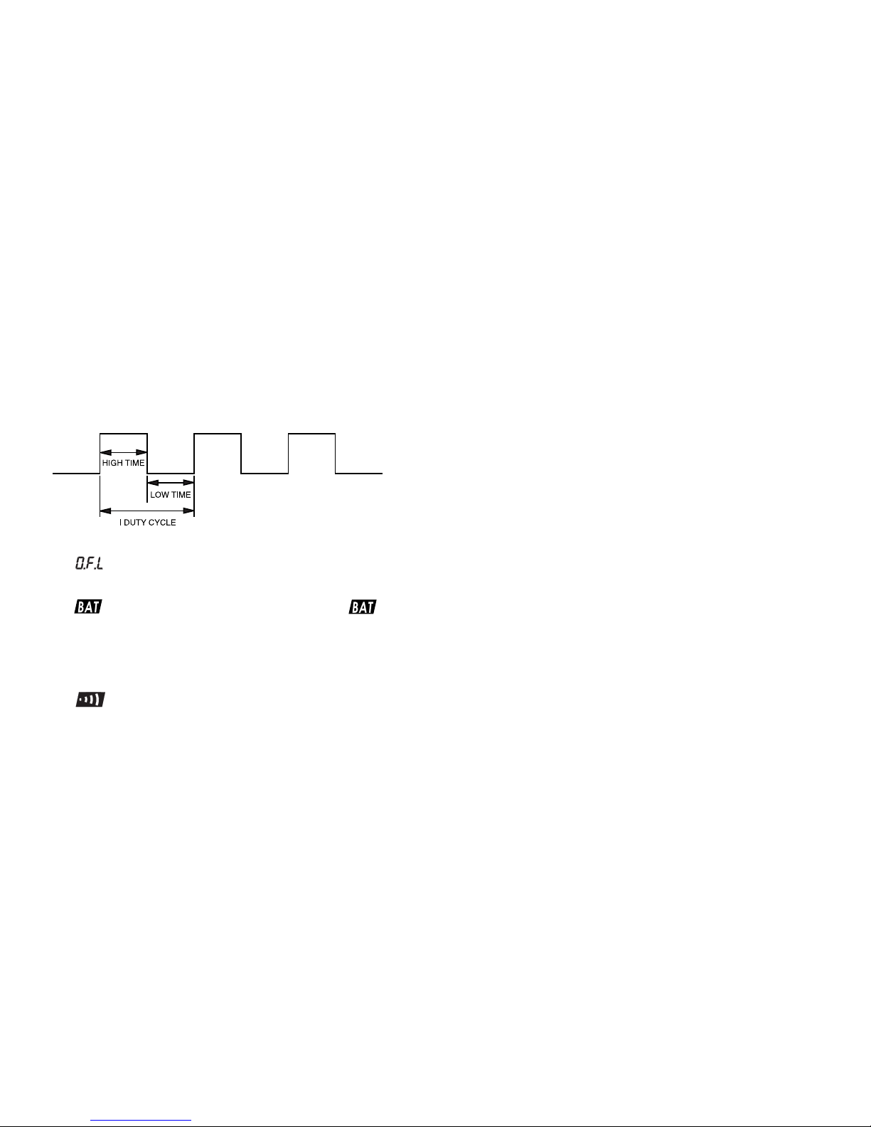
18 – ± . Indicates a – (negative) or + (positive) trigger slope when
a trigger slope is selected.
A negative (–) trigger slope should be selected to measure
low (–) time and a positive (+) trigger slope should be
selected to measure high (+) time. For example, when
measuring a Duty cycle of Mixture Control Solenoid, the low
(–) time is the On time in most cases.
19 – (Overload Indication) . Displayed on the LCD when
input value is too large to display.
20 – (Low Battery) . Battery life warning. When is
first turned on, at least 8 hours of battery life remain.
Replace the battery immediately. Never leave a weak or
dead battery in the Meter. Even leak-proof types can leak
and damage the Meter.
21 – . Displayed when the Meter is in the continuity test
function.
22 – HOLD . Displayed when the Hold mode is selected.
23 –
88
STR. Displayed when either 2 or 4 strokes are selected in
the RPM mode. Press the STR button to toggle between 2-
stroke engines and 4-stroke engines.
14 15
24 –
88
CYL . Displayed when a certain number of cylinders is
selected in the RPM or Dwell mode. Press the CYL button to
toggle between 1,2,3,4,5,6,8 cylinder engines.
When the Meter is in the Temperature mode, °
CC
or °
FF
is
displayed from °
88
. Press the °C/°F button to toggle between
°
CC
and °
FF
.
25 – DWL¡. Displayed when the Dwell mode is selected.
26 – % . Displayed when the Duty cycle mode is selected.
27 – mS (Milliseconds, 1 x 10-
3
seconds) . Displayed when the
mS-Pulse Width mode is selected.
28 – The following symbols indicate the unit of the value
displayed.
DWL° The number of degrees of distributor rotation
when the points remain closed, measured for
1 to 8 cylinders.
%Percent, used for duty cycle measurement
°C/°F Centigrade or Fahrenheit temperature
measurement
VVolts
mV Millivolts (1 x 10-
3
Volts)
ΩOhms
KΩKilohm (1 x 10
3
Ohms)
MΩMegohm (1 x 10
6
Ohms)
Hz Hertz (1 cycle/sec)
KHz Kilohertz (1 x 10
3
cycles/sec)
29 – RPM . Displayed when the RPM mode is selected. In this
mode, revolutions per minute on 2 or 4 stroke engines are
measured using the Inductive Pickup on a spark plug wire.
30 – ANALOG DISPLAY SCALE. Displayed with 41 position
analog pointers.

Using Inductive Pickup
The Meter comes with an Inductive Pickup. The Inductive Pickup
takes the magnetic field generated by the current in the spark plug
wire and converts it to a pulse that triggers the Meter’s RPM
measurement.
Using (Optional) Clamp-on Current Probe
The Meter sometimes has to be used to make a high current
measurement. In higher current applications where high accuracy
is not needed, a clamp-on current probe is very useful.
There are two basic types of current probes; current transformers
(CT), which measure ac current only and Hall effect probes, which
can measure ac or dc current.
The output of a Hall effect probe is typically 1000 to 1, however the
current is converted to a voltage. For example, 1 millivolt equals 1
amp dc or ac so that 100 amps ac is converted to 100 mV ac. The
probe leads are connected to the “V” and “COM” input terminals
and the Meter function switch is set to “mV” setting.
A Hall effect ac/dc current probe is optionally supplied with the
Meter.
16 17
The Meter has two power-on options.
Auto-Power-Off Mode
The meter automatically turns off after approximately 20 minutes of
no activities to extend the battery life.
To disable the Auto-power-off mode, turn the Meter on by pressing
the ON/OFF button while holding down the HOLD button for more
than 2 seconds.
Continuous Turn-on of LCD Segments
Each time the Meter is powered on by pressing the ON/OFF
button, all LCD segments will turn on for two seconds as part of a
selftest routine.
To turn all LCD segments on continuously, turn the Meter on by
pressing the ON/OFF button while continuously pressing the
RANGE button.
4. POWER-ON OPTIONS
Voltage Measurements
WARNING!
TO AVOID THE RISK OF ELECTRICAL SHOCK AND
INSTRUMENT DAMAGE, INPUT VOLTAGES MUST NOT
EXCEED 600 V DC OR AC RMS. DO NOT ATTEMPT TO TAKE
ANY UNKNOWN VOLTAGE MEASUREMENT THAT MAY BE IN
EXCESS OF 600 V DC OR AC RMS.
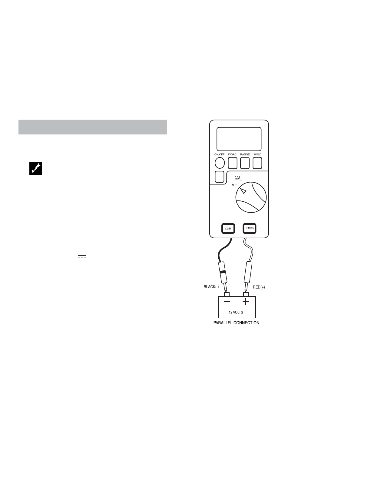
NOTE: When taking voltage measurements, this Meter must
be connected in PARALLEL with the circuit, or circuit
element under test.
To measure voltage:
• Select the Voltage (V or mV) range with the rotary switch.
• Press the DC/AC button to select AC or DC.
Insert
• Black lead in COM jack.
• Red lead in RPM, V, Ωjack.
Touch the Black probe to the negative (–) circuit or to ground.
Touch the Red probe to the circuit coming from the power source.
5. BASIC ELECTRICAL TESTS AND MEASUREMENTS
18 19
■■Accuracy
A measurement range determines
the highest value the Meter can
measure. Most Meter functions
have more than one range. Being
in the right measurement range
is very important when measuring.
Selection of a lower range will
move the decimal point one
place and increase the accuracy
of the reading.
An
O.F.L
(overload) display
means the range is too low;
select the next higher range.
■■Analog Bar Graph
The bar graph is easier to read
when the data causes the digital
display to rapidly change. It is
also useful for trend setting or
directional data.

Resistance Measurements
Resistance is measured in Ohms (Ω) and the values can greatly
vary from a few Milliohms (mΩ) for contact resistance to billions of
ohms for insulators. The Meter can measure down to about 0.1
Ohms and measure as high as 40 MΩ.
WARNING!
TURN OFF POWER AND DISCHARGE ALL CAPACITORS ON
CIRCUIT TO BE TESTED BEFORE ATTEMPTING INCIRCUIT
RESISTANCE MEASUREMENTS. ACCURATE MEASUREMENT
IS NOT POSSIBLE IF EXTERNAL OR RESIDUAL VOLTAGE IS
PRESENT.
NOTE: The resistance in the test leads can affect accuracy in
the 400 Ωrange. Short the leads together and subtract
the test lead resistance from the resistance
measurements.
20 21
To measure resistance:
•Select the Resistance (Ω)
setting with the rotary switch.
•If a more accurate measurement
is desired, select the proper
Resistance range using the
RANGE button.
Insert:
•Black lead in COM jack.
•Red lead in RPM, V, Ωjack.
Touch the test lead probes
across the resistance or circuit
to be tested.
■■Accuracy
Rapidly changing display
readings (noise) can sometimes
be eliminated if you change to a
higher range.
Continuity Test
A DMM with a continuity beeper allows you to quickly and easily
distinguish between an open and a closed circuit. The Meter beeps
when it detects a closed circuit or short, so you do not have to look
at the Meter during the test. This can be a valuable troubleshooting
aid when determining: good or blown fuses and fusible links, open
or shorted conductors and wires, the operation of switches, etc.
NOTE: Turn the power off to the circuit to be tested. A beeper
tone does not necessarily mean zero resistance.
22 23
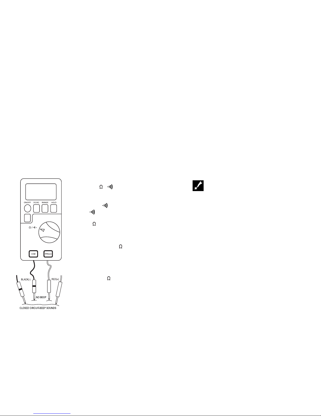
To test circuit continuity:
•Select the / setting with the
rotary switch and press the
DC/AC button to select the
continuity ( ) range.
The symbol appears on the
display and the Meter defaults to
the 4 K range.
Insert:
•Black lead in COM jack.
•Red lead in RPM, V, jack.
Connect one test probe to each end
of the circuit to be tested.
•If circuit is closed, the Meter will
beep @ < 100 .
•If circuit is open, there is no beep.
RPM Measurements Using the Inductive Pickup
RPM refers to revolutions per minute. Using the inductive pickup,
which comes with the Meter, RPM can be measured by clamping it
around any spark plug wire of a two stroke or a four stroke
automotive engine. The inductive pickup takes the magnetic field
generated by the current flown in the spark plug wire and converts
it to a pulse that triggers the Meter’s RPM measurement.
Using the inductive pickup allows you to make RPM
measurements on any 2 or 4 stroke automotive engine with any
number of cylinders without physically touching any wires.
WARNING!
THE IGNITION SYSTEM CAN GENERATE A POTENTIAL
SHOCK HAZARD. ENSURE THAT THE ENGINE IS OFF
BEFORE CONNECTING OR REMOVING THE INDUCTIVE
24
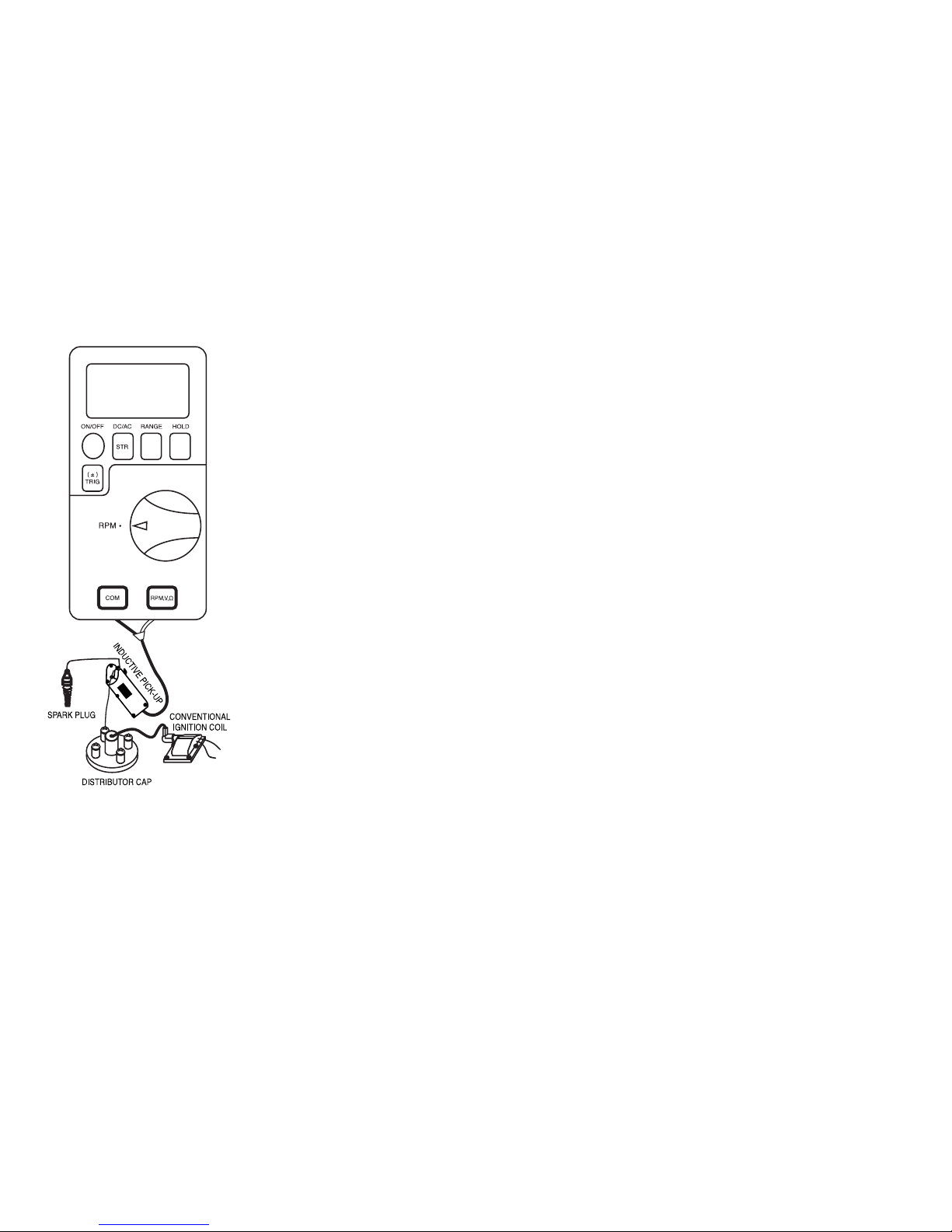
To measure RPM:
•Select the RPM range with
the rotary switch.
•Press the DC/AC button to
select either 2 or 4 stroke
engine.
Insert:
•The DUAL BANANA CON-
NECTOR into the input jacks
as shown. Ensure that the
plug with the GROUND TAB
goes into the COM jack.
Connect the inductive pickup
to a spark plug wire and start
the engine. If no reading is
received, unhook the pickup,
turn it over and connect again.
If the reading is too high or
unstable, adjust trigger level.
NOTE:
1. Position the pickup as far
away from the distributor
and the exhaust manifold
as possible.
2. Position the pickup within
six inches of the spark
plug or move it to another
plug wire if no reading or
an erratic reading is
received.
25
Pulse Width Measurements
Pulse Width is the length of time an actuator is energized. For
example, fuel injectors are activated by an electronic pulse from
the Engine Control Module (ECM). This pulse generates a
magnetic field that pulls the injector nozzle valve open. The pulse
ends and the injector nozzle is closed. This Open to Close time is
the Pulse Width and is measured in milliseconds (mS).
The most common automotive application for measuring pulse
width is on fuel injectors. You can also measure the pulse width of
the fuel mixture control solenoid and the idle air control motor.
This exercise shows how to measure Pulse Width on Port Fuel
Injectors.

To measure pulse width (mS):
•Select the mS-Pulse range with
the rotary switch.
•Press the ± TRIG button for 2
seconds until the negative (–)
trigger slope is displayed on the
lower left side of the display.
NOTE: The applied time for
most fuel injectors is
dis-played on the
negative (–) slope.
Insert:
•Black lead in COM jack.
•Red lead in RPM, V, Ωjack.
Connect:
•Jumper wires between the fuel
injector and the harness
connector.
•Black test probe to a good
ground at the fuel injector or the
negative (–) vehicle battery post.
•Red test probe to the fuel
injector solenoid driver input on
the jumper cable.
Start the engine. A pulse width in
milliseconds should be read.
If reading is too high or unstable,
adjust the trigger level pressing the
±TRIG button repeatedly.
26 27
Dwell Measurements
Dwell is the number of degrees of distributor rotation where the
points remain closed. Dwell can be measured for 1,2,3,4,5,6,8
cylinder engines using the Meter so you need to determine how
many cylinders are in the engine to measure Dwell.
In the Dwell mode, the Meter defaults to 4 cylinders so DWL°,
44
CYL and TRIG on the display. If you want to select the other
number of cylinder, press the CYL (RANGE) button repeatedly to
select the required number of cylinders.
This exercise shows how to measure Dwell.
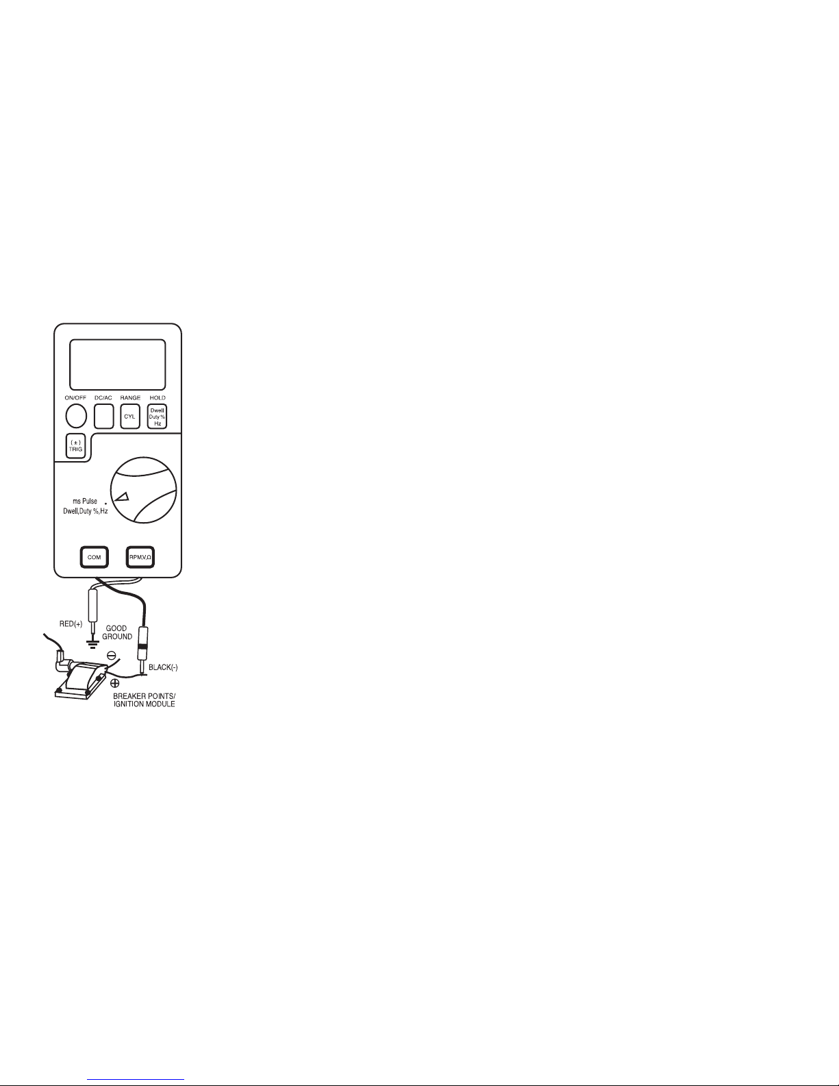
To measure Dwell:
•Select the mS-Pulse range
with the rotary switch.
•Press the HOLD (DWELL)
button until DWL°,
4
CYL,
TRIG, and – appear on the
display.
Insert:
•Black lead in COM jack.
•Red lead in RPM, V, Ωjack.
Connect:
•Red test probe to a good
ground or the negative (–)
vehicle battery post.
•Black test probe to the wire
that connects to the breaker
points.
Press the CYL (RANGE) button
repeatedly to select the required
number of cylinders.
Start the engine and observe the
reading.
Adjust trigger level pressing the
±TRIG button repeatedly, if the
reading is too high or unstable.
28 29
Duty Cycle Measurements
Duty Cycle is the percentage (%) of time that voltage is positive
compared to negative: On compared to Off. There are many
signals on a vehicle where you might be required to measure duty
cycle. Signals from Mixture Control Solenoid of a feedback
carburetor, signals from Cam or Crank sensors and the control
signals for fuel injectors are good examples.
This exercise shows how to measure duty cycle on the signal for
the mixture control solenoid of a feedback carburetor using the
Meter.
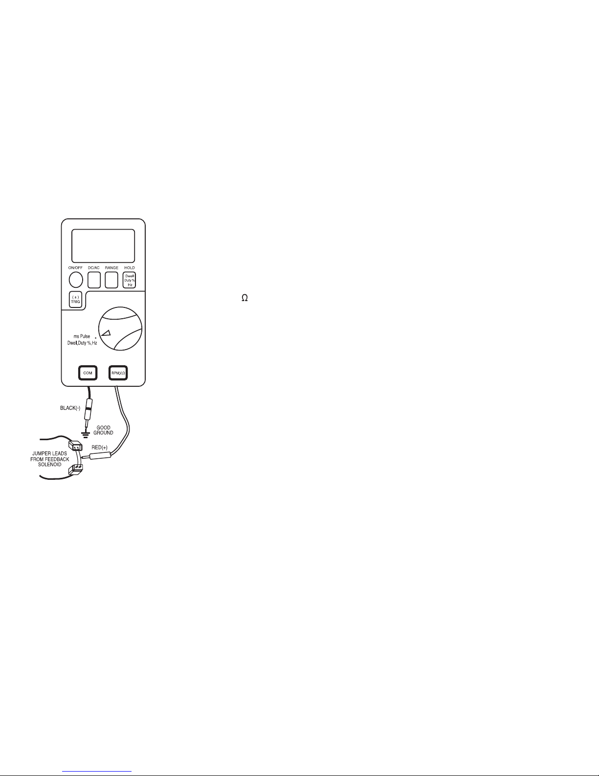
To measure duty cycle (%):
•Select the mS-Pulse range
with the rotary switch.
•Press the HOLD (DUTY %)
button until % appears on
the right side of the display.
Insert:
•Black lead in COM jack.
•Red lead in RPM, V, jack.
Connect:
•Black test probe to a good
ground at the carburetor or
the negative (–) vehicle
battery post.
•Red test probe to the
solenoid signal.
Press the ± TRIG button for 2
seconds to toggle between the
negative (–) and positive (+)
slope.
Start the engine. A duty cycle
of approximately 50 % should
be read.
Adjust the trigger level
pressing the ± TRIG button
repeatedly if reading is too
high or unstable.
30 31
Most car have the points of the
solenoid closed for a duty cycle
between 50 ~ 70%.
Once the engine warms up and
goes into open loop, the duty
cycle should fluctuate.
NOTE: Consult the car’s service
manual to verify slope
assigned to position for
each component.
Frequency (Automotive Hz) Measurements
[ Model: 228 Only ]
Frequency (Hz) is the number of times a voltage pattern repeats
positive compared to negative, On Compared to Off, during 1
second of time. There are many sensors and signals on a vehicle
that have a frequency that can be measured. Wheel Speed
sensors, Vehicle Speed sensors, Fuel Injector control signals,
Cam and Crank outputs and engine reference signals are good
examples.
This example measures the frequency output of a digital Mass Air
Flow sensor. Depending on the type of MAF sensor, the output
can be from several hundred to ten thousand Hz.
NOTE: Although similar in appearance, MAF sensors made by
different manufacturer function differently, have
different frequency range’s square waves and are not
Interchangeable. Voltage level of square waves should
be consistent. Frequency should change smoothly
with engine load and speed.
32 33
Frequency (Non-Automotive Hz) Measurements
[ Model: 226 Only ]
The Meter has two frequency measurement modes: The non-
automotive Hz measurement (Approximate Trigger Level: 300 mV)
mode for the general frequency counter mode and the automotive
Hz measurement mode for the automotive mesurement.
In the non-automotive Hz measurement mode, the Meter
autoranges to one of four ranges: 199.99 Hz, 1999.9 Hz, 19.999
KHz and 199.99 KHz.
If the input signal is below the trigger level, frequency
measurement will not be taken. If your readings are unstable, the
input signal may be near the trigger level for that range. You can
usually correct this by selecting a lower range using the RANGE
button. If your readings seem to be a multiple of what you
expected, your input signal may have distortion or ringing like the
signals from electronic motor controls. In this case, use the
automotive Hz measurement mode to get the correct readings.
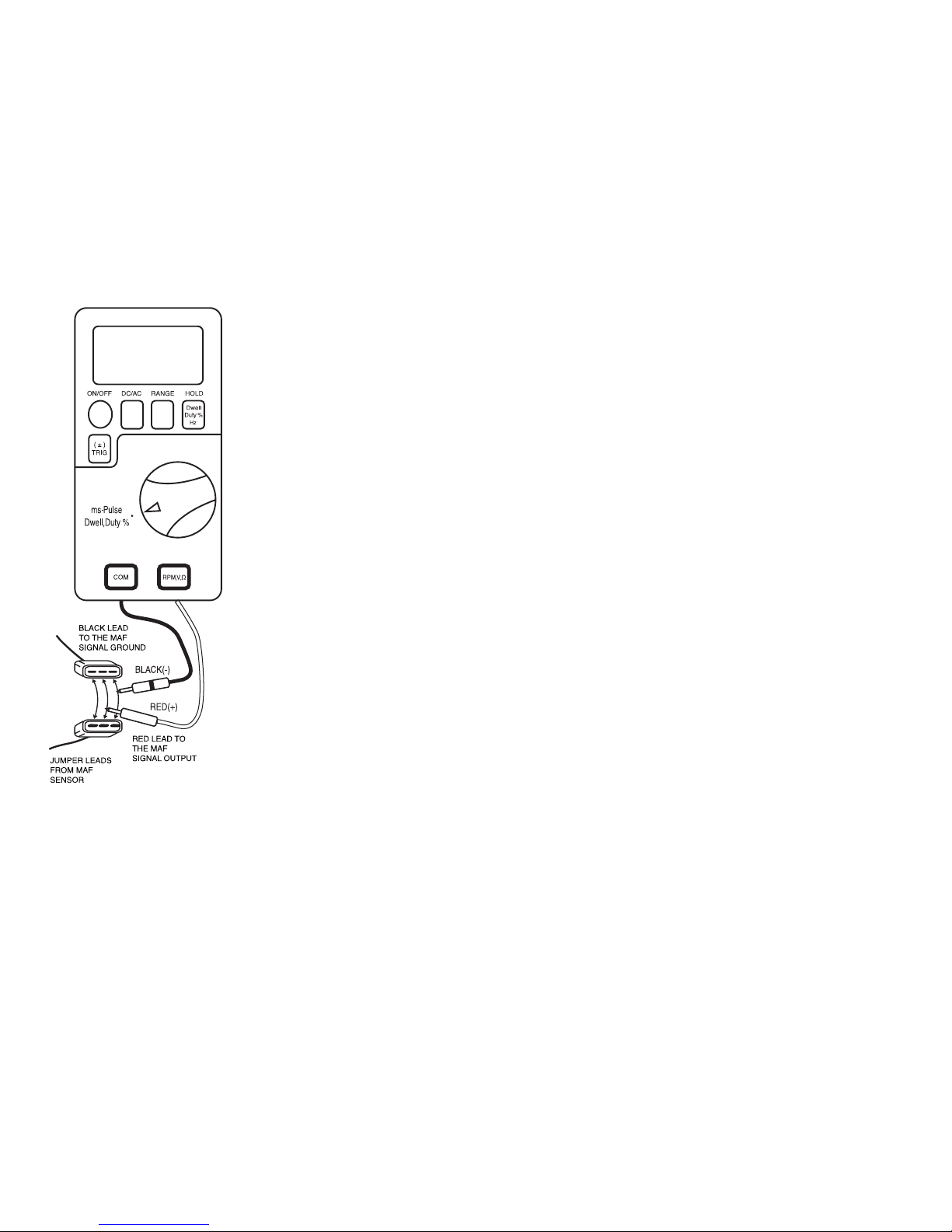
To measure frequency (Hz):
•Select the mS-Pulse range
with the rotary switch.
•Press the HOLD (Hz) button
until Hz appears on the right
side of the display.
Insert:
•Black lead in COM jack.
•Red lead in RPM, V, Ωjack.
Connect:
•Jumper wires between the
MAF sensor and the harness
connector.
•Black test probe to the
ground jumper wire.
•Red test probe to the signal
output jumper wire.
Start the engine. At idle, note
the frequency displayed on the
Meter. Move the throttle and
note the change in frequency
displayed.
If reading is unstable, adjust
the trigger lever pressing the ±
TRIG button repeatly.

To measure frequency (Hz).
•Select the Hz setting with the
rotary switch.
Insert:
•Black lead in COM jack.
•Red lead in RPM, V, ΩHz
jack.
Connect:
•The Black test probe to
GROUND side.
•The Red test probe to the
“SIGNAL OUT” wire of the
object to be tested.
NOTE: The display will show
00.00 Hz for frequen-
cies below 0.5 Hz.
34 35
Temperature Measurements [ Model: 228 Only ]
CAUTION!
DO NOT ALLOW TEMPERATURE PROBES TO CONTACT ANY
LIVE VOLTAGE THAT MAY EXCEED 30 V AC RMS OR 42 V AC
PEAK OR 60 V DC. UNPLUG TEMPERATURE PROBE BEFORE
TAKING MEASUREMENTS OTHER THAN TEMPERATURE. TO
AVOID HEAT DAMAGE TO THE METER, KEEP IT AWAY FROM
SOURCES OF VERY HIGH TEMPERATURE. THE LIFE OF
TEMPERATURE PROBE IS ALSO REDUCED WHEN EXPOSED
TO VERY HIGH TEMPERATURES (OPERATING RANGE IS -40
°F TO 2,498 °F).
NOTE: This Meter automatically defaults to the Centigrade
scale. To measure in Fahrenheit, toggle the DC/AC
button when the rotary switch is set to TEMP position.

To measure temperature:
•Select the TEMP setting with
the rotary switch.
•Press the DC/AC button to
toggle between °C and °F.
Insert:
•The thermocouple adaptor and
thermocouple into TEMP
(RPM, V, Ω) and COM jack.
Touch the end of K– type
thermocouple to the area or
surface of the object to be
measured.
NOTE: To avoid error, it is very
important to use a
thermocouple adaptor
whose materials match
the thermocouple you
are using.
These basic diagnostic tests begin by checking the main source of
power and the chassis ground circuit connections. Ground circuits
are one of the least understood but potentially most troublesome
areas of automotive electronics. One of the most frustrating
electrical problems you will encounter in an automobile is a high
resistance ground. This can create some very strange symptoms
that seem to be unrelated to the cause. The symptoms can include
problems with turn signals, lights that stay dim, the wrong lights
turning on, transmission shifting problems, gauges that change
when certain accessories are operated, or even lights that will not
turn on at all. You can find a bad ground by checking the voltage
between the component’s ground wire and a clean chassis ground
or the negative vehicle battery terminal. An excessive voltage drop
in a ground circuit affects the entire electrical circuit. This is why it
is so important to make sure the basic circuits are in good shape
before checking trouble codes in the on-board computer and
individual components.
Battery Tests
(1) No Load Test
This test checks for battery charge state. A fully charged battery
will display at least 12.6V. Since voltage tests only show the
charge state, not the battery condition, you should also perform a
load test to indicate the battery’s performance.
6. BASIC AUTOMOTIVE DIAGNOSTIC TESTING
36 37
This manual suits for next models
1
Table of contents
Other Finest Measuring Instrument manuals


Popular Measuring Instrument manuals by other brands

Kestrel
Kestrel 2000 manual

Dynastream Innovations
Dynastream Innovations AMP 231 user guide

Capintec
Capintec AreaExpert user guide

Electro Industries/GaugeTech
Electro Industries/GaugeTech Shark 270 quick start guide

Hanna Instruments
Hanna Instruments HI764 instruction manual

YOUYANG
YOUYANG PAPI 400 user manual


