Finest 705 Series User manual

Model 705 & 707 Series
True RMS Multimeters
USER’S
MANUAL
FINE INSTRUMENTS CORPORATION
FINE INSTRUMENTS CORPORATION
341-5, SONGNAE-DONG, SOSA-GU, BUCHON-SHI, KYUNGGI-DO
KOREA
-TEL: (82-32) 668-6042 -FAX: (82-32) 656-5844
-E-mail: [email protected]
© Copyright 2003 Fine Instruments Corp. All right reserved.
Specifications subject to change without notice.
Litho in Korea.
a world leader in test & measurement
Basic Specifications
DC Voltage : 0 to 1000 V
AC Voltage, true RMS : 15 mV to 1000 V – 50 kHz bandwidth
Basic Accuracy : DC voltage – 0.05%
(Model 707)
, 0.1%
(Model 705)
AC voltage – 0.3%
(Model 707)
, 0.5%
(Model
705)
DC Current : 0 to 10 A (20A for 30 seconds)
AC Current, true RMS : 25 µA to 10 A (20A for 30 seconds)
Resistance : 0 to 50 MW
Conductance : 0 to 20 nS
Capacitance : 0.001 nF to 5 mF
Frequency : 0.5 Hz to 5 MHz
Duty Cycle : 0.1 % to 99.9 % for 0.5 Hz to 300 kHz
(pulse width > 3 µsec.)
Diode Test : 3.0 V
Temperature : –50 C to 1300 C (–58 F to 2372 F)
Memory Location : 20
Continuity Check : Beep at Approx. < 10 (response time < 1ms)
1. Safety Information 2
2. Electromagnetic Compatibility (EMC) 3
3. Controls and Indicators 4
4. Rotary Switch and Pushbutton Overview 7
5. Meter Operation and Special Features 15
6. Maintenance 27
7. Specifications 29
Limited Warranty & Limitation of Liability
SOURCES LIKE SMALL HAND-HELD RADIO
TR ANSCEIVERS, FIXED STA TI ON RA DIO
AND TELEVISION TRANSMITTERS, VEHICLE
RA DIO TR ANSM IT TERS AND CEL LUL AR
PHONES GENERATE ELECTROMAGNETIC
RADIATION THAT MAY INDUCE VOLTAGES
IN THE TEST LEADS OF THE MULTIMETER.
IN SU CH CASES THE ACCURA CY O F T HE
MULT IMETER C ANNOT BE GUARAN TEED
DUE TO PHYSICAL REASONS.
WARNING!
Warning
Read Safety Information” before using this Meter.
CONTENTS
1

INTERNATIONAL ELECTRICAL SYMBOLS
AC (Alternating Current)
DC (Direct Current)
Either AC or DC
Caution! Refer to the explanation in this manual.
Caution! Dangerous voltage (Risk of electric shock)
Earth (Ground)
Double insulation or Reinforced insulation
Fuse
Battery
The meters meet EN61326 : 1997
+
A
1
: 1998. See the backside o
f
this manual’s
cover page.
This manual contains information and warnings that must be followed for operating
the meter safely and maintaining the meter in a safe operating condition.
I
f
the meter is not
used in a manner specified in this manual
,
the protection
provided by the meter may be impaired.
The Model 707 and Model 705 comply with IEC 1010-1 (1995), UL 3111-1 (6. 1994),
EN 61010-1 (1995), CSA C 22
.
2 No, 1010.1 - 92 ; Overvol
t
age 1000
V
Category III.
TERMS IN THIS MANUAL
AWarning identifies conditions and actions that could pose serious hazards to the
user. A
Caution identi
f
ies
conditions and actions
t
hat could cause damage the
meter or the equipment under test.
Warning
Do not expose the meter to rain or moisture in order to reduce the risk of fire or
electric shock. To avoid any electrical
shock hazard, observe the proper safety
precautions when working with
voltages above 60 V dc or 30V ac rms, these
voltage levels pose a
potential
shock hazard to the
user
.
Inspect
test leads,
connectors and probes for damaged insulation or exposed metal before using the
meter. If any defects are found, replace them immediately. Do not touch test lead
tips or the circuit being tested while power is applied to the circuit under test.
Always keep your
f
ingers
behind the
f
inger guards o
f
the
test leads during
measurement
.
Do not measure any circuit that draws more than the protection
f
use’s
current rating. Do not
attempt the protection fuse’s voltage ra
t
ing. Never
attempt a
voltage measurement with the test lead inser
t
ed into the mA µA or A
input
terminal. When servicing
t
he meter, use
only specified replacement par
t
s.
Remove test leads from the meter before you open the battery door. Do not operate
the meter with
t
he battery door removed or loosened. To avoid false readings,
which could result in possible electric shock or personal injury, replace the battery
as soon as the low battery indicator appears. Avoid working alone.
Caution
Disconnec
t
the
t
est leads from the
test poin
t
s
before changing
functions.
Disconnect circuit
power and discharge all
high voltage capacitors be
f
ore testing
resistance, continuity, capacitance or diodes. Always set the meter to the highest
range and work downward for an unknown
value in the manual ranging mode.
Before measuring
current,
check the
meter’s fuses and turn power OFF to the
circuit before connecting the meter to the circuit.
1. SAFETY INFORMATION
2. ELECTROMAGNETIC COMPATIBILITY (EMC)
32

Although this manual describes the operation of both Model 705 and Model 707, all
illustrations and examples assume use of Model 707.
(1) 4-4/5 digit, 50000 (Primary display) / 5000 (Secondary
display) count LCD
display [Model 707]
3-4/5 digit, 5000 (primary display)/5000 (Secondary display) count LCD display
[Model 705]
(2) On screen menu selection push-buttons
(3) Push-buttons for special functions & features
(4) Selector to turn the power ON or OFF and select a function
(5) Input terminal for 10A (20A for 30 sec.) current measurement function
(6) Input terminal for milli-amps and micro-amps current measurement function
(7) Common (Ground reference) input terminal for all measurement functions
(8) Input terminal for all
functions E
X
CEPT current (A, mA
,
µA) measurement
functions
(9) RS-232 Optical interface
Glossary of Terms for Digital Multimeter
s
Average sensing RMS calibrated
RMS (Root-Mean-Square) is the term used to describe the effective or equivalent
DC value
of an AC
signal. Most digi
t
al
multime
t
ers use average
sensing RMS
calibrated
t
echnique to measure RMS values
of AC signals. This
technique is
to
ob
t
ain the average value by rectifying and filtering
the AC signal. The average
value is then scaled upward (that is, calibrated) to read the RMS value of a sine
wave. In measuring pure sinusoidal waveform, this technique is fast, accurate, and
cost effective. However, in measuring non-sinusoidal waveforms, significant errors
can be introduced because of different scaling factors relating average to RMS
values.
True RMS
True
RM
S
is a
term which identifies a DMM that accurately responds
t
o the
effective RMS value regardless of the waveform shapes such as square, sawtooth,
triangle, pulse trains, spikes, and transient glitches as well as distorted waveforms
with the presence of harmonics.
(1)
(3)
(4)
(7)
(8)(5)
(6)
(2)
3. CONTROLS AND INDICATORS
54
(9)

Non-sinusoidal waveforms may cause :
– Overheated tansformers, generator and motors to burn out faster than normal
– Circuit breakers to trip prematurely
– Fuses to blow
– Neutrals to be overheated due to the triplen harmonics present on the neutral
– Bus bars and electrical panels to vibrate
Crest Factor
Crest Factor is the ratio of the Crest (instantaneous peak) value to the True RMS
value, which is commonly used to define the dynamic range of a True RMS DMM.
A pure sinusoidal waveform has a Crest Factor of 1.414.
A badly distorted sinusoidal waveform normally has a much higher Crest Factor.
NMRR (Normal Mode Rejection Ratio)
NMRR is the
DMM’s ability to reject
unwanted AC noise ef
f
ect which
can cause
inaccurate DC measurements. NMRR is typically specified in terms of dB (decibel).
The Meter has a NMRR specification of > 60dB at 50Hz/60Hz, which means a good
ability to reject the effect of AC noise in DC measurements.
CMRR (Common Mode Rejection Ratio)
Common mode voltage is voltage existing on both
t
he COM and Voltage input
terminals of
a DMM, with respect
t
o ground. CMRR is a DMM’s ability to reject
common
mode voltage
effect which can cause digit rattle
or offset in voltage
measurements. The Meter has a CMRR specification of > 60dB at DC to 60 Hz in
AC volts measurement function and > 120 dB at DC, 50Hz and 60Hz in DC volts
measurement function.
Burden Voltage
Burden voltage is a voltage drop across the input terminals of a current-measuring
device, caused by internal shunt resistance.
Burden voltage contributes measurement error, and should be as low as practical.
Temperature Coefficient
Temperature Coefficient is a fac
t
or
used to calculate the change in indication or
output of an instrument with changes in temperature.
Uncompensated changes in temperature contribute uncertainty by an amount
determined by the temperature coefficient to instrument.
Analog Bar-graph
The analog bar graph provides a visual indication of measurement like a traditional
analog me
t
er’s needle. It
is excellent
in detec
t
ing faulty contacts, identi
f
ying
potentionmeter’s clicks and indicating signal spikes during adjustments.
Turning the Meter On
To turn the meter on, turn the rotary switch from OFF to any switch setting.
If you want a view of the full display (all segments illuminated), press and hold the
HOLD button while turning the meter on. Release the button after viewing the full
display.
Rotary Switch
Turn the meter on by selecting any measurement function. The meter presents a
standard display for that function (range, measurement units, on screen menu bars,
etc.).
The display may also be influenced by
some of the choices made in on
screen menu selection.
Use the on
screen menu selection buttons
to select any
ro
t
ary swi
t
ch alternate
function.
Y
ou can also use other bu
t
tons to choose modifiers for the selected
function.
When you turn the rotary switch from one function to another, a display for the new
function appears.
Button choices made in one function do not
carry over into
another function.
OFF. Turns the meter off. Setup parameters and stored measurements are
saved.
.Millivolts ac rms and dc measurement. Compatible with various adaptors.
.Volts ac rms, Volts dc, Volts ac+dc total rms, Volts ac dc dual display,
dBm, and dB.
Hz . Frequency measurement. Duty cycle and pulse width are also
displayed if they are turned on in the on screen menu.
4. ROTARY SWITCH AND PUSHBUTTON OVERVIEW
76

WAccess to resistance measurement, continuity test, and capacitance
measurement. Conductance (1/W) is also displayed in secondary display
when measuring resistance.
.Diode measurement.
Temp . Temperature measurements in degrees Centigrade or Fahrenheit.
.Micro-amps ac rms, micro-amps dc, micro-amps ac+dc total rms, and
micro-amps ac dc dual display
.Amperes ac rms, amperes dc, amperes ac+dc total rms, and amperes ac
dc dual display.
Milli-amps ac rms, milli-amps dc, milli-amps ac+dc total rms, and
milli-amps ac dc dual display.
9
8
USER-FRIENDLY ROTARY SWITCH SELECTIONS
Position
Rotary Switch Function
On Screen Menu Selection Primary
Display
When the menu key is pressed
Secondary
Display
Primary
Display Secondary
Display
T
r
ue R
M
S
A
C and DC
m
illi
v
olt
m
ea
s
u
r
e
m
ent
f
r
o
m
0
m
V
to 500.00
m
V
and
A
dapt e
r
s
applications
AC AC
-
AC+DC or AC DC Dual
Display (press to toggle)
AC+DC total
RMS volts
Hz
AC DC
AC+DC total
RMS volts
Hz
AC DC
DC
-
T
r
ue R
M
S
A
C
v
olt
s
m
ea
s
u
r
e
m
ent
(
default
)
from 0 V to 1000.0 V
DC -
AC dBm
AC Hz
DC volts measurement from 0V to 1000.0V DC -
AC volts and dBm or dB measurement AC dBm
DC
dBm
AC Hz
DC -
AC
DC
AC dB
600
W
r E F
dB
SET
AC HzAC
AC+DC or AC DC Dual
Display (press to toggle)
Hz
H
z
m
ea
s
u
r
e
m
ent
(
default
)
f
r
o
m
0.5 H
z
to
5.0000 MHz % (Duty Cycle) Hz
%
Hz Pulse Width
(ms)
Dut
y
C
y c
le
(
%
)
m
ea
s
u
r
e
m
ent f
r
o
m
0.1% to
99.9 % (Pulse Width > 3µ sec) Hz
ms
Hz % ms (Pulse Width) Hz
set
DC
AC Hz
Hz
DC

Pushbuttons
The buttons ac
t
ivate features that
augment
t
he function selected with
the rotary switch.
RANGE.
Use the RANGE button to manually select a range. Press and hold RANGE button
for two seconds to return the meter to auto range mode.
The meter is in auto range mode when the AUTO indicator is on.
The range and units are displayed on the LCD.
MIN/MAX.
Press this button to scroll through the minimum, maximum, and average value. The
minimum (MIN) reading is displayed first
and
this
mode calculates an average
(AVG) of all readings taken since the mode was activated. The meter beeps when
a new maximum or minimum reading is updated.
In the MIN/MAX mode,
the primary display continues to show the present
measurement value.
Press and hold the MIN/MAX button for two seconds to exit MIN/MAX mode.
Auto Power Off feature will be disabled automatically in this mode.
1ms PEAK.
Press this button momentarily
to activate
1ms peak hold mode to
capture transient voltage or current signal events as short as 1ms with its display
resolution of 5,000 counts. The LCD displays the 1ms and MAX indicators at the
upper left corner and and EXIT indicators in the on screen menu selection and
the meter will display a captured maximum value. Press the menu key. The LCD
displays the 1ms and MIN indicators and +and EXIT indicators in the on screen
menu selection and the meter will display a captured minimum value. Press the +
menu key to capture a maximum value again, if you want. The meter beeps when a
new maximum or minimum reading is updated. Press either the 1ms PEAK button
or the EXIT menu key in order to exit 1ms peak hold mode. Auto Power Off feature
will be disabled automatically in this mode.
REL .
Use this button to set the meter to relative (
) mode and make relative
measurements. The reference value for the measurement can be a measured,
or a programmed value. The reference value appears in the secondary display and
the difference value appears in the primary display.
11
USER-FRIENDLY ROTARY SWITCH SELECTIONS
(cont.)
Position Rotary Switch Function On Screen Menu Selection Primary
Display
When the menu key is pressed
Secondary
Display
Primary
Display
Secondary
Display
–
Capacitance –
V
––
Temp
Resistance measurement from 0to
50M S= 1/
Diode test V–
F
SET –
Temperature measurement C–
AC Hz
AC DC
DC –
AC+DC total
RMS micro-amps Hz
DC current measurements (default) from
0 A to 5000.0 A
True RMS AC current measurements
from 0 A to 5000.0 A
DC –
AC Hz
AC Hz
DC current measurements (default) from
0 mA to 10.000 A
True RMS AC current measurements
from 0 mA to 10.000 A
DC –
AC Hz DC
DC
AC
AC+DC or AC DC Dual
Display (Press to toggle)
AC DC
AC+DC total
RMS amps
AC+DC or AC DC Dual
Display (Press to toggle)
DC –
AC
* V RMS = VAC2+ VDC2(AC+DC total RMS volts)
* IRMS = I AC2+ I DC2(AC+DC total RMS amps)
* dBm readout = 10 x log (primary display readout 2/R), where R = 600 (default)
* dB readout = 20 x log (primary display readout /ref), where ref = 1V (default)
10

MEM.
Use the memory mode to store and recall measurement values.
P
ress the MEM bu
t
ton momentarily in order to activate the memory mode. The
display shows four
menu selections: Store, Recal
l
, Clear and EXIT.
Store. Select Store to store
the held value in
t
he next available memory location.
The memory
location number momentarily shows on
t
he secondary display
.
If no
memory loca
t
ions are available, shows on the secondary display for two
seconds and
nothing is
stored, when you mus
t
clear
t
he memory locations using
the Clear key in order to store
t
he held value.
Recall. Selec t
Recall to review the s tored value using the menu key. The
secondary display shows the
value stored in
t
hat loca
t
ion. Whenever you press +
or – menu key,
the next or previous stored value will
be shown in
the primary
display and the secondary display momen
t
arily shows
the corresponding memory
location.
Clear. Select Clear to clear all the stored values. When you press Clear key, the
me
t
er will ask you with
t
he display o
f
“
” along wi
t
h the On Screen
Menu Selections of
AC (stands for ALL Clear), Clear and EXIT. When you press
the Clear key, the
displayed value
in
the primary display is erased. When you
press
the AC
key
,
all
the stored values are erased and
the word
shows on
the
display
.
Press E
X
IT
key
to exit memory mode wi
t
hout
erasing the
s
t
ored
values.
E
X
IT
.
Select EX
I
T to exit memory mode. You can also exit memory mode
by
pressing MEM button or turning
the rotary knob position.
(Backlight) Button. Press
t
he MEM ( ) button until
the backligh
t
is turned
on or off.
On Screen Menu Select
i
on Keys.
E
ach setting of the rotary switch to
a measurement function position may activate
one or more menu selection key se
t
tings on
the LCD.
If there is more than one measurement for a rotary switch se
t
ting, a
menu appears
on the display. Press the corresponding menu selection key to select
t
he desired
measurement.
< to a Measured Value >
When you take the measurement and the meter settles on the measurement value,
press this button.
For subsequent readouts, the settled reference value is subtracted from the actual
measurement.
< to a Programmed Value >
Set
t
he meter to
t
he measurement function and range you want and then press the
button.
While the
meter is in mode,
press
t
he min/max button then the setup
menu appears.
Use the on screen
menu selection buttons
t
o edit
t
he desired reference value and
press the menu selection button 4 for EXIT.
To
exit
mode, press the button.
For subsequent readouts the
programmed reference
value is subtracted
from the
actual measurement. The
programmed reference
value is los
t
when the meter is
turned of
f
.
HOLD.
Press
this
button to
turn HOLD mode on
and off. When the hold mode is
activated,
t
he meter beeps, freezes the display, and displays the
HOLD indicator
on the LCD
.
Hold
mode freezes the display for later view.
Auto Hold. To ac
t
ivate auto hold mode, press down the HOLD but
t
on on until A–
and HOLD indicators appear on the LCD.
This mode is not
available for capacitance measurement.
In
t
his mode the display automatically freezes and
t
he meter beeps when the
measurement reading
is stabilized. The displayed value
will be updated when a
new measurement
value is s
t
abilized.
This mode
is very useful when it is impossible for you to press
the HOLD button
or
see the meter display while probing
and
t
aking measurements.
1312

Enable or D
i
sable the beep alert warning overranges
The meter displays
in
the secondary display,
(or
) in the primary
display and +, ,
EXIT
in
the on screen menu selection. You can toggle
/
by
pressing the +,
menu keys. Press
the EX
I
T menu key to get into
t
he next
Setup.
Enable or Disable
the beep a
l
ert warning the
incorrectly connected test leads
The me
t
er
displays
in the secondary display,
(or
) in the primary
display and
+,
, EXIT in the on screen
menu selection. You can
toggle
/
by pressing the +,
menu keys. Press
the E
X
IT menu key in order to save the
newly customized default values in any Setup during
t
he entire
Setup cycle. The
meter will return to the
original range just af
t
er
is displayed in the primary
display.
Use the menu selection keys in order to
edit setup values as
f
ollows.
RS-232C PC-to-Meter Communications
The meter equips with
an optically isolated
inter
f
ace port at the top
f
or
t
he data
communication. The RS 70 optical adapter cable and the WS 70 software disc are
required to connect
the meter to
the PC computer. The
meter comes with these
standard accessories. Refer to the README file in the WS 70 for further details.
Setup Mode
The Setup Mode allows you
to customize
defaul
t
settings. To activa
t
e the Setup
Mode, press the menukey 4 while the
display shows all segments on at
power
on
reset.
Y
ou can customize the following de
f
ault settings
in sequence during
t
he S etup
cycle. The
newly customized default values
i
n any Setup can be saved only
when the entire Setup cycle is
ended. The
meter displays at the end of
the entire Setup cycle. The Setup values are saved on EEPROM so they cannot be
lost when the meter is turned off.
Enable or D
i
sable the auto-power-off
mode
The meter displays in the secondary display, (or ) in
t
he primary
display and +, ,
EXIT in the
on screen menu selection. You can toggle /
by
pressing
the +, menu keys. Press the EXIT menu key to get in
t
o the
next Setup.
Auto-power-off time (in minutes)
The meter
displays
MIN
at the upper
le
f
t corner, in the secondary display, a
two digit number in the primary display and +, ,
, EXIT in the on
screen menu
selection.
Y
ou can setup
a new auto-power-off
time (in minu
t
es) by
using the +,
,
and
menu keys. You can
adjust the au
t
o-power-off
t
ime between 1 minute
and 60 minutes. Press the
EXIT menu key to
get into the
next Setup.
Backlight auto-off time (in seconds)
The me
t
er displays
in the
secondary display, a
t
wo digi
t
number in the
primary display and +, , ,EXIT in the on
screen menu selection.
Y
ou can setup
a new backlight auto-off
time (in seconds) by using
the +, ,
and menu keys.
You can adjust the backlight auto-off time between 1 second and 60
seconds.
Press the EXIT menu key to get
into the next
S
etup
.
Enable or
Disab
l
e the
power saving
mode beep alert
The
meter displays
in
the secondary display, (or
) in the primary
display and +, ,
EXIT
in the on screen menu selection. You can toggle
/
by
pressing the +,
menu keys. Press
the E
X
IT menu key to get into
the next
Setup.
Enable or Disable
the backlight on when the meter is po
w
ered on
The meter displays
in the secondary
display,
(or ) in the
primary
display and +, , EXIT in
the on screen menu selection. You
can toggle
/
by pressing the +, menu keys. Press the EXIT menu key
t
o ge
t
into the next
Setup.
Key + – EXIT
Function
Press to
increase
setting value.
Press to
decrease
setting value.
Press to step to
next digit in
setting value.
Press to move
tonext Setup.
Press to save all
settings andexit
Setup mode when
settingis ended.
1514
Voltage ( , ) Measurements
Ranges available in volts functions
are :
•
50.000mV
,
500
.
00m
V
DC and 500.00mV AC
(Model 707)
50.00mV, 500.0mV DC and 500.0mV AC (Model 705)
•
5.0000 V, 50.000V, 500.00V
,
1000.0V
*d
B
m readout = 10
x log (primary display readout
2
/
R
), where R = 600 (default)
dB readout =
20 x log (primary display
readou
t
/ ref)
,
where re
f
= 1V (default)
Making Measurements
All measurements are made by first
setting the measurement func
t
ion knob to a
function setting (so that the meter is put in the default measurement function) and
then selecting a measurement from the menukeys. Note that not all function knob
settings have corresponding menukey settings.
For example, the steps below show how to make a dc voltage measurement:
1. Set the measurement function knob to for a voltage measurement. Then, the
meter is set to the default ac voltage measurement mode.
2. Select the menukey 2 for dc voltage measurement.
3. Connect the test leads to the measurement points.
5. METER OPERATION AND SPECIAL FEATURES
16 17
Measurement Menukey Connect leads Primary
display Secondary
display
DC
DC millivolts (default)
(no selection)
–
Measurement Menukey Connect leads Primary
display Secondary
display
True RMS AC
voltage (default)
DC voltage
dBm
dB
AC+DC total RMS
AC DC dual display
(no selection)
DC
dBm or dB
(press to toggle)
AC+DC or
AC DC (press to
toggle)
AC
DC
AC
AC
Hz
–
dBm
dB
AC +DC
AC
Hz
DC
AC AC AC Hz

Both
AC and DC Vo
l
tage Measurements
When a
dc volts function
is selected, the me
t
er can display the combined ac + dc
(rms) value or ac and dc
components of a signal separately by using
the On
Screen Menu Selection but
t
on.
When the meter shows ac over dc (ac voltage in the
primary display and dc
voltage in the secondary display), the other pushbut
t
on functions just except the
RANGE but
t
on are not available.
Application : Using AC + DC and AC DC in Volts Mode
To take the combined AC+DC total RMS volts measurement, press the menukey 4.
In the above example the total RMS of 6.1188 V shows on the primary display and
the frequency of 60.00 Hz shows on the secondary display. When calculating the
power dissipated in a circuit component, it is critical that the DC value is factored
into the equation V
RMS
x I
RMS
, where V
RMS
is AC + DC total RMS.
Another useful feature of this Meter is AC DC dual display mode. AC voltages riding
on power supplies can cause problems with electronic circuits. If the Meter is set to
DC Volts mode, the display shows the DC component of 6.0000V. However, the AC
component may be missed. It is recommended that you set the meter to AC DC
dual display mode by pressing the menukey 4 twice. The primary display shows the
1.2000 V
A
C voltage and the secondary display shows the 6.000V DC voltage.
That
is , AC DC mode
all ows you
t
o s imultaneous ly mak e
AC and DC
measurements without changing the meter settings.
When measuring
vol
t
age,
the meter acts like a 10 M impedance in parallel with
the circuit. This loading effect
can cause
measurement
errors in high–impedance
circuits. in most cases, the error is negligible (0.1% or less) if
the circuit impedance
is
10 k or less.
AC Voltage Measurements
All pushbutton features are available in
t
his
f
unction.
The On Screen
Menu
Selection accesses decibel (dBm or dB) measurements.
dB (dBm or dB V) Measurements in AC Volts Function
The ac volts function allows you to display readings as deviations in dB (decibels)
above or below an established reference level.
Set up dB measurements by using the On Screen Menu Selection buttons when
measuring ac volts. The dBm (or dB V)value appears in the secondary display and
the ac reading appears in the primary display.
Normally, dB is
measured as dBm, which is a measure of decibels relative to 1
milliwatt. The meter assumes a resistance of 600 in making this calculation. This
resistance can be set for any value from 1 to 1999 by using the set-up menu
selection buttons. When measuring dB V, the reference voltage can be set for any
value from 0.1000 V to 5.0000 V by using the set-up menu selection buttons.
DC Voltage Measurements
A
ll pushbutton features are available
f
or
a standard dc volts reading
.
18
dB = 20 x log (Vx¡ÀVr)
•For dBm, Vr is the voltage across the reference resistance
at 1 milliwatt. For example, Vr would be 0.7746 V with a
600
reference resistance.
• For dB V, the reference voltage is 1 V.
19
The duty cycle mode is optimized for measuring the ON or OFF time of logic and
switching signals. Systems such as electronic fuel injection systems and switching
power supplies are controlled by pulses of varying width, which can be checked by
measuring duty cycle.
Positive and Negative Duty Cycle
To measure duty cycle, set duty to either positive or negative by using the Menukey
4. When you measure negative duty cycle, a “–” symbol shows in the secondary
display.
Positive duty cycle : % duty = x 100 (above trigger point)
Negative duty cycle : % duty = (1– ) x 100 (below trigger point)
Pulse Width Measurement
The pulse width measurement function allows you to measure the amount of time a
signal is high or low within a given
period. The measured
wave
f
orm must
be
periodic.
Frequency (Hz) Measurements
The meter autoranges to one of six frequency ranges :
50.000 Hz, 500.00 Hz, 5.0000 KHz, 50.000 KHz, 500.00 KHz and 5.0000 MHz.
The meter beeps to indicate when a particular pushbutton is not
allowed
when
measuring frequency. The 1ms Peak button cannot be used.
* The meter defaults at
negative
edge triggering in the frequency measurement
mode. When you set positive edge triggering by pressing the Menukey 4,
is displayed in the secondary display.
* You can turn on positive or negative duty cycle by pressing the Menukey 4.
Duty Cycle Measurements
Duty Cycle (or Duty Factor) is the percentage of time a signal is above or below a
trigger level during one cycle.
Measurement Menukey Connect leads Primary
display
Secondary
display
Frequency
Freque
n
c
y and duty
cycle
d
ualdisplay
Frequency and pul se
width
d
ual dis
p
lay
(no selection)
%
ms
Hz
Hz
Hz
Duty Cycle (%)
Pulse Width (ms)
20 21
a
ba
b

Continuity Test
The continuity function detects intermittent opens and shorts lasting as little as 1
millisecond.
These brief con
t
acts cause the meter to emit a short beep
.
This
function is convenient for checking wiring connections and operation of switches, A
continuous beep tone indicates a complete wire.
The 1 ms PEAK, MIN/MAX and REL functions are not available when continuity
is selected.
Conductance for High Resistance Tests
Conductance
,
the reverse of
resistance
,
is
t
he ability of a circuit to pass curren
t
.
High
values of conductance correspond to low values of resistance. The
unit of
conductance is the Siemens (S).
Resistance ( , , ) Measurements
(Ohms, Continuity, and Capacitance)
The
available resistance ranges are 50.000 , 500.00 , 5.0000 K ,
50.000 K ,
500.00 K , 5.0000 M , and 50.000 M .
‘
Tips for measuring resistance
Because the meter’s test current flows through all possible paths between the test
probe tips, the measured value of a resistor in a circuit is often different from the
resistor’s rated value.
The test leads can add 0.1 to 0.2
of error to resistance measurements.
To measure the resistance of the leads, touch the probe tips together and read
the resistance.
If necessary, you
can press the
REL bu
t
ton to automatically
subtract this value.
The resistance function can produce enough voltage to forward-bias silicon diode
or transistor junctions, causing them to conduct. Do not use the 50 MWrange for
measuring the in-circuit resistance to avoid this.
Caution
To avoid damaging the meter or the equipment under test,
remove all power from the c ircuit and dis charge all high-
voltage capacitors before measuring resistance.
Measurement Menukey Connect leads Primary
display
Secondary
display
Resistance (default)
Continuity
Capacitance
(no selection)
S
(conductance)
capacitance
or
(beeps on short)
–
22 23
Caution
Using resistance and continuity function in a live circuit will
produc e
f
alse results and may damage the instrument.
I
n
many c as es t he
suspi cious c omponent s mus t be
disconnected from the circuit under test to obtain accurate
results.
Normal forward voltage drop ( forward biased ) for a good silicon diode is between
0.4V to 0.9V. A reading higher than that indicates a leaky ( defective ) diode. A zero
reading indicates a shorted ( defective ) diode.
An indicates an open diode ( defective ).
Reverse the test leads connections ( reverse biased ) across the diode. The display
shows if the diode is good. Any other readings indicate the diode is shorted or
resistive ( defective ).
Temperature (Temp) Measurements
* Be sure to insert the banana plug k-type temperature bead probe TP7 with correct
+ – polarities. You can also use a thermocouple probe adapter TP1 A (Optional
purchase) to adapt other standard k-type temperature probes.
Current ( , ) Measurements)
Capacitance Measurement
The available capacitance ranges are 5nF, 50nF, 500nF, 5µF, 50µF, 500µF and 5
mF.
Tips for measuring capacitance
•To speed up measurements of similar values, press RANGE to manually select
the proper range.
• To measure small values of capacitance accura
t
ely,
press REL with
t
he tes
t
leads open to subtract the residual capacitance of the meter and test leads.
Diode ( ) Test
Use the diode test to check diodes, transistors, silicon controlled rectifiers (SCRs),
and other semic onduc tor dev ices .
The tes t sends a current through a
semiconductor junction, then measures the junction’s voltage drop.
Caution
To
avoid damaging the
meter or the equipment under
test,
remove all power
f
rom the circuit and discharge all high-
voltage capacitors before measuring capacitance.
Large value
capac itors
should be discharged
t
hrough
an
appropria
t
e resistance load
.
Use
t
he dc voltage function to
confirm that the capacitor is discharged.
Caution
Discharge all high-voltage capacitors before testing diodes.
Large
value capacitors should be dis charged through an
appropriate resistance load.
Measurement Menukey Connect leads Primary
display Secondary
display
Diode
(no selection)
24
V –
25
Measurement Menukey Connect leads Primary
display Secondary
display
Celsius temperature
(default)
Fahrenheit temp-
erature
C
F
–
–
SET
(no selection)
Warning
Never a
t
tempt an in-circuit current measurement where the
open-circuit potential to earth is greater than 1000 V. You may
damage the meter or be injured if the fuse blows during such
a measurement.
Caution
Check the meter
f
uses before measuring
current
.
Use the
pr oper terminal s,
func ti on
,
and
r ange for current
measurements. Never
place the probes in parallel wi
t
h any
circuit or component when the test leads are plugged into the
current terminals.
Warning
Do not
apply thermocouple
to circuits exceeding 30V rms
42.4V peak
or 60V dc.
The available current ranges
are 500.00 µA, 5000.0 µA, 50.000 mA
,
500
.
00mA,
5.0000 A, and 10.000 A.
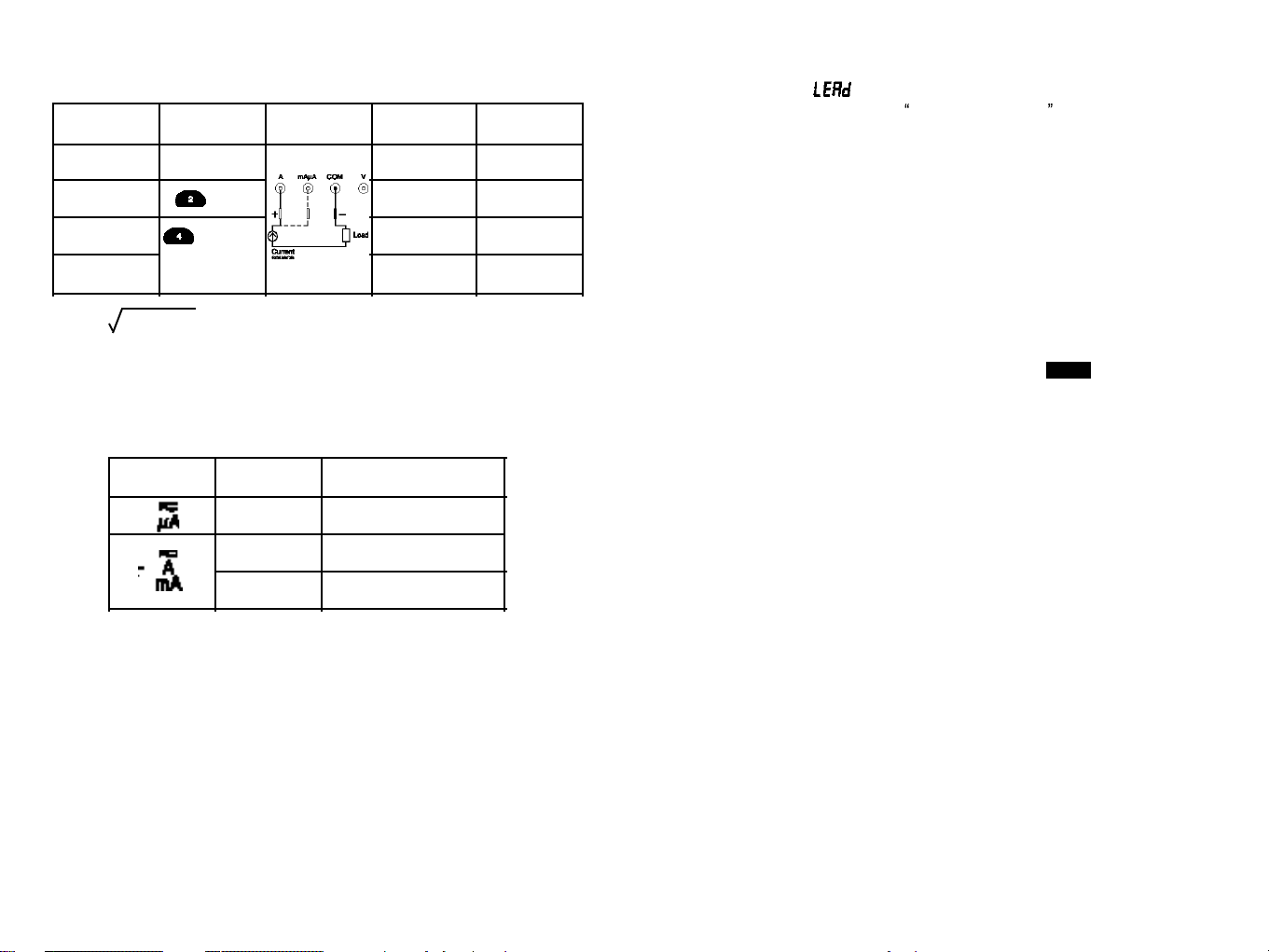
To measure ac or dc current,
1. Turn off power to the circuit and discharge all high-voltage capacitors.
2. Insert
t
he black lead into the COM terminal and the red lead into an inpu
t
terminal appropriate for the measurement range as the following table.
* To avoid blowing the meter’s 440 mA fuse, use the mAµA
terminal only if you are sure the current is less than 400mA.
3.
Open the circuit path to be tested. Touch the red probe to the more positive side
of the break and touch the black probe to the more negative side of the break.
(Reversing the leads will produce a negative reading, but will not damage the
meter.)
4. Turn on power to the circuit and read the display.
5. After measuring current, turn off power to
the circuit
and discharge all
high-
voltage capaci
t
ors.
Disc onnect
the meter and restore the
circui
t
to normal
operation.
Measurement Menukey Connect leads Primary
display
Secondary
display
True RMS AC Amps
(default)
(no selection)
DC Amps
DC
AC + DC total RMS
AC + DC or
AC DC
(press to toggle)
AC DC dual display
AC Hz
–
Hz
DC
DC
AC + DC
AC
* I
RMS
= I
AC 2
+ I
DC2
(AC+DC total RMS amps)
Rotary Switch Input
Ranges
mAµA
mAµA
A
500.00 µA, 5000.0 µA
50.000 mA, 500.00 mA
5.0000 A, 10.000 A
26
Wrong Input Warning Feature
If the display shows or Fuse, be sure the meter is set up correctly and test
t
he
meter’s fuses as described under Auto
Fuse De
t
ection in chapter
6. If
the rotary
switch is no
t
correctly set to
one of the curren
t
measuring
positions, the beeper
warns you by making a chirping sound. This warning is intended to stop you
f
rom
attempting
to measure the other values when the leads are plugged into a curren
t
terminal.
Placing the probes in parallel with a powered circuit when a lead is plugged into a
current terminal can damage the circuit you are testing and blow the meter’s fuses
because the resistance through the meter’s current terminals is so low tha
t
the
meter acts like a short circuit.
Auto / Manual Range Operation
Press the RANGE button momentarily to select manual-ranging, and the meter will
remain in the range it was in, when the LCD annunciator
AUTO
turns off.
Press the button momentarily again to step through the ranges. Press and hold the
RANGE button for two seconds or more to resume auto-ranging.
* Manual-ranging feature is not available in Hz function.
Beeper
A single beep indicates correct operation. A double beep indicates a warning or
error condition
.
Continuous
beeping indicates there is
circui
t
continuity while in
continuity mode.
Auto – Power – Off
The Auto- Power-Off feature has two steps . The
fir st step
has the me
t
er
automatic al ly go into the power savi ng mode to ex tend battery l ife after
approximately 15 minutes of no activities. When the meter enters the power saving
mode, the meter beeps warning tones every minute. To turn on the meter, press
any button or move the rotary switch to any position
.
The second step is to
automatically turn the meter completely off after approximately 15 minutes from the
time when the meter entered the power saving mode. To turn on the meter after
auto-power-off, turn the rotary switch to any desired position from OFF position.
You can disable auto-power-off by using Setup Menu. Both the auto-off time and
the power saving mode beep alert time can be adjusted by Setup Menu.
27

Replace the battery or the fuses as follows :
1. Turn the rotary switch to OFF and remove the test leads from the input terminals.
2. Remove the battery door by using a screwdriver.
3. Replace
t
he battery or the
f
uses with
ONLY
speci
f
ied replacement battery or
fuses.
4. Reinstall the battery door by using a screwdriver.
Trouble Shooting
I
f
the
meter fails to operate
even with the bat
t
ery or fuse replacements, check it
twice over according to operating procedure as described in this manual.
If the meter’s V/ input terminal has subjected to high voltage transient (caused by
lightning or swi
t
ching surge to the
system) by accident or abnormal operating
conditions, the series fusible resistors will be blown off like fuses in order to protect
the user and the meter. Most measuring functions through this terminal will then be
open circuit.
In this case, the series fusible resistors and the spark gaps should be replaced by
qual ified
personnel. Refer to the
LIMITED WARRANTY & LIMITAT
I
O
NOF
LIABILITY section for obtaining warranty or repairing service.
Cleaning and Storage
Periodically wipe the cas e with a damp cloth and mild detergent
;
do not us e
abrasives or solvents.
Clean the input terminals as follows :
1. Turn the meter off and remove all test leads.
2. Shake out any dirt that may be in the terminals.
3. Soak a new swab with alcohol and work the swab around in each terminal.
If the meter is not to be used for periods of longer than 60 days, remove the battery
and store it separately.
Auto Fuse Detection
The meter automatically verifies the integrity of the internal fuses when you set the
rotary function knob to
and
plug 1
test lead into either
A
terminal or mAµA
terminal. In either case, if an open fuse is detected, the word “ ” shows on the
primary display.
Battery and Fuse Replacement
The meter uses a single standard 9 V battery (NEDA 1604, JIS006P, IEC 6F 22), a
1000V/440mA IR 10k
A
fast acting F
f
use (F
71
) for mAµA current inpu
t
, and a
1000V/11A IR 10kA fast acting F fuse (F
72
) for A current input.
6. MAINTENANCE
Warning
To avoid electrical shock or personal injury, remove the test
leads and any input signals before replacing the bat
t
ery or
fuses. To prevent damage or injury, install only the same type
of fuses or equivalents.
28 29
Warning
To avoid false readings, which could lead to possible electric
shock or personal injury, replace the battery as soon as the
low battery indicator appears.

Battery Type : Single 9V battery –NEDA 1604, JIS 006P or
IEC 6F 22
Battery Life
:
150 hrs. typical (with backlight off)
Shock Vibration
:
Per MIL-T-PRF 28800 for Class II instruments
Pollution Degree : 2
Electromagnetic
Compatibility (EMC)
:
Susceptibility – Commercial Limits for
EN 50082-1
Emissions – Commercial Limits for EN 50081-1
Size (H x W x D) : 208 x 103 x 54 mm
(not including mounted accessory)
Weight
:
Approx. 655g
Warranty : 3 years
Calibration Interval : 1 year
Feature Summary
Backlight : For clear readings in poorly lighted areas
Fast Autoranging : Meter automatically selects the best range-
momentarily
AC + DC total RMS : Choices for AC only, AC+DC readings or AC
(@40Hz to 10 kHz)
DC dual display
dBm, dB V : User selectable impedance references for dBm
:
User selectable voltage references for dB V
Auto HOLD
:
Holds readings on display
Continuity / Open test : Beeper sounds
Fast Bar Graph : 25 segments for peaking and nulling
Safety & Compliances
Maximum voltage between any terminal
and earth ground : 1000 V ac/dc
Compliances : Complies with CSA C22.2 No 1010.1-92,
ANSI/ISA-S82, 01-94 to 1000 V Overvoltage
Category lll.
Certifications : UL & cUL standard UL 3111-1 Listed
CE-marking certificated
Surge Protection : 8 kV peak per IEC 1010.1-92
Fuse Protection for mA or µA inputs : 1000 V / 440 mA lR 10 kA Fast fuse
Fuse Protection for A input : 1000 V / 11 A lR 10 kA Fast fuse
Physical Specifications
Display (LCD) : Digital – 50000 (Model 707) /
5000 (Model 705) count
primary display, 5000 count secondary
display ; updates 4 / sec. nominal
Analog – 25 segments, updates 40 / sec.
Operating Temperature : 0 C to 50 C
Storage Temperature
:
–20 C to 60 C
Temperature Coefficient : nominal 0.15 x (specified accuracy) / C
@(0 C to 18 C or 28 C to 50 C),
or otherwise specified
Relative Humidity : 0 % to 80 % @ (0 C to 35 C)
0 % to 70 % @ (35 C to 50 C)
Altitude : Operating – up to 2000m
Storage – 10000m
7. SPECIFICATIONS
30 31

AC Voltage
CMRR : > 60dB @ DC to 60 Hz, Rs = 1 K
Input Impedance : 10 M , 30 pF nominal
(50M , 100 pF nominal for 500 mV range)
DC Current
AC Current
Memory Locations : 20
Duty Cycle / Pulse Width : Measure the time signal is ON or OFF in % or
milliseconds
MIN/MAX Mode
:
Record maximum, minimum, and
average values
1ms PEAK Mode : Captures peaks to 1 millisecond
Closed-Case Calibration : No internal adjustments needed
Battery / Fuse Access Door : Battery or fuse replaceable without voiding
calibration
High-Impact Overmolded Case : Protective holster features
Electrical Specifications
Accuracy is given as ± ([% of reading] + [number of digits]) at 18 C to 28 C with
relative humidity up to 80%, for a period of one year after calibration.
True
RM
S
responding accuracies are
speci
f
ied from 10% to 100% of
range or
otherwise specified; Crest Factor < 3:1 at full scale and < 6:1 at half scale.
DC Voltage
NMRR : > 60dB @ 50/60 Hz
CMRR : > 120 dB @ DC, 50/60 Hz, Rs=1k
Input Impedance : 10 M , 30 pF nominal
(50M , 100 pF nominal for 50 mV & 500 mV ranges)
Range 705 707 705 707
Accuracy
50 mV 10 µV 1 µV
0.1% + 3
0.05% + 10
500 mV 100 µV 10 µV
0.1% + 2
5 V 1 mV 100 µV
50 V 10 mV 1 mV
500 V 100 mV 10 mV
1000 V 1 V 100 mV
0.05% + 2
Resolution
32
0.1% + 2
33
Range 705 707 40 Hz – 1 kHz 1 kHz – 5 kHz 5 kHz – 20 kHz 20 kHz – 50 kHz
Accuracy
705 707
705 707 705 707 705 707
500 mV 100 µV 0.5%+5
5 V 1 mV
0.5%+2
50 V 10 mV
500 V 100 mV
1000 V 1 V
10 µV
100 µV
1 mV
10 mV
100 mV
0.8%+5
1.0%+5 1.0%+10
0.8%+2 0.5%+10
0.8%+5
0.5%+20
2.0%+5
0.8%+2 0.5%+10
Unspecified
Unspecified
Unspecified
Unspecified
5.0% 5.0%
1.2%+2 0.8%+20
Resolution
Range 705 707 40 Hz – 1 kHz 1 kHz – 10 kHz
Accuracy
705 707 705 707
500 µA 100 nA
5 mA
1 µA
0.5% + 2
50 mA 10 µA
500 mA 100 µA
5 A 1 mA
10 nA
100 nA
1 µA
10 µA
100 µA
0.3% + 5
1.0% + 5
Unspecified Unspecified
10 A 10 mA 1 mA
0.8% + 10
Resolution
Range 705 707 705 707
Accuracy
500 µA 10 nA
5 mA 100 nA 0.5 % + 2
50 mA 1 µA
500 mA 10 µA
5 A 100 µA
10 A
100 nA
1 µA
10 µA
100 µA
1 mA
10 mA 1 mA
0.1 % + 5
Resolution
0.5 % + 5
0.3 % + 10
0.3 % + 20
0.4% + 10
0.4% + 20
0.8% + 10
2.0%+20
0.3%+10
0.3%+10
0.4%+10

Conductance (5.000 counts only)
Continuity
Diode Test
Capacitance (5.000 counts only)
*
1.
Accuracy with film capacitor or better
*
2.
Using Relative ( ) mode
3.5 % + 5
( AC + DC ) Voltage and ( AC + DC ) Current
Resistance
Open Circuit Voltage : < 1.3 V dc
*
1.
Using Relative ( ) mode
Function 705 / 707
40 Hz – 1 kHz 1 kHz – 10 kHz
Accuracy
705
707 705 707
DC mV 100 µV 0.8% + 5
DC V
1 mV
10 mV
100 mA
UnspecifiedUnspecified
Range
500 mV
5 V
50 V
500 V
1000 V 1 V
DC µA 100 nA
1 µA 0.5% + 3 0.5% + 3
0.8% + 10 0.8% + 10
DC mA
DC A
10 µA
100 µA
1 mA
1.0% + 5 1.0% + 5
500 µA
5 mA
50 mA
500 mA
5 A
10 A 10 mA
Resolution
Range 705 707 705 707
Accuracy
50 0.01 0.001 0.5% + 5 *
1
0.5% + 20 *
1
0.3% + 2 *
1
0.1% + 5 *
1
0.5% + 4 0.3% + 5
1.0% + 4
0.5% + 20
500 0.1 0.01
5 k 1 0.1
50 k 10 1
500 k 100 10
5 M 1 k 100
0.1% + 2
50 M 10 k 1 k
Resolution
34
0.8% + 5 0.8% + 5
0.8% + 3
0.8% + 5
0.8% + 5
0.8% + 3
0.8% + 5
0.5% + 5
0.5% + 3
0.5% + 5
0.5% + 3
35
Range Resolution Accuracy
20 nS 0.01 nS 0.1% + 10
Range Accuracy Open Circuit Voltage
4V 2% + 1
Test Current
(Typical)
1 mA < 3.0 V dc
Audible threshold : the beeper sounds if the measured resistance is lower than 10 ,
and turns off when greater than about 70 .
Response time : < 1 msec.
Range 705 707
Accuracy
*
1.
5 nF 1 pF 1.0% + 5
*
2.
2.0 % + 3
1.0 % + 5
*
2.
2.0 % + 3
1.0 % + 3
*
2.
1.0% + 3
*
2.
3.0 % + 3 3.0 % + 3
50 nF 10 pF
500 nF 100 pF
5 µF 1 nF
50 µF 10 nF
500 µF 100 nF
5000 µF 1 µF
Resolution
3.5 % + 5

LIMITED WARRANTY & LIMITATION OF LIABILITY
Fine Instruments Corporation (Finest) warrants this product to be free from defects
in material and workmanship under normal use and service for 3 years
.
This
warranty
extends
only to the original buyer or end-user customer of a Finest
authorized reseller, and is not applied to fuses, battery or to any product which, in
Finest’s option, has been misused, altered, neglected or damaged by accident or
abnormal conditions of operation or handling.
Fines t warrant s
t
hat so
f
tware will operate on appropriate Fines
t
ins truments
substantially in accordance with its functional specifications for 90 days and that it
has been properly recorded on non-defective media. Finest does not warrant that
software will be error free or operate without interruption.
Finest authorized resellers shall extend this warranty on new and unused products
to end-user customers only but have no authority to extend a greater or different
warranty on behalf of Finest.
Finest’s warranty obligation is limited, at Finest’s option, to refund of the purchase
price
,
or free of charge repair or replacement of a defective
product which is
returned to the Finest’s factory within the warranty period.
To obtain warranty service, contact your nearest Finest authorized reseller or send
the product, with a description of the difficulty, postage and insurance prepaid (FCA
Destination), to the nearest Finest authorized reseller. Finest assumes no risk for
damage in transit. Finishing warranty repair, the product will be returned to Buyer,
transportation prepaid (FCA Destination). If Finest determines that the failure was
caused by misuse, acciden
t
, abnormal c ondition
of operation / handling,
or
alteration, Finest will provide an estimate of repair costs and obtain authorization
before commencing the repair work. Finishing repair, the product will be returned to
t
he Buyer transpor
t
ation prepaid and the Buyer will
be billed for the repair and
return transportation charges (FCA shipping Point).
Warranty service is available outside the Republic of Korea only if product
was
purchased through a Finest Authorized Sales Outlet in the country of use. Finest
reserves the right to invoice Buyer for importation costs of repair/replacement parts
when product purchased in one country is submitted for repair to the Finest factory
in the Republic of Korea.
DISCLAIMER
THIS WARRANTY IS
IN LIEU
O
F ANY OTHER WARR
A
NTIES, E
X
PRES
S
ED OR
IMPLIED
,
INCLUDING ANY WARRANT
Y
OF MERCHANTABIL
I
TY
O
R FITNESS
FOR
A PART
I
CULAR
PURPOSE. FINEST SHALL NOT B
E
LIABLE FOR ANY SPECIAL,
I
NDIRECT, INCIDENTAL OR CONSEQUENTIAL DAMAGES O R LOSSES,
I
NCLUDING LOSS OF DATA
,
WH
E
THER
ARIS
I
NG FROM BR
E
ACH OF
WARRANTY
OR BASED ON CONTRACT,
TORT,
REL
I
ANCE OR ANY OTHER THEORY.
Frequency, Duty Cycle, Pulse Width and Temperature
dBm and 1 ms PEAK Hold (5.000 counts only)
Burden Voltage ( A, mA, µA)
Function
Accuracy
705 707
Frequency
[ Minimum
Frequency:
0.5 Hz
Sensitivity :
250 mV ]
0.001 Hz
0.01 Hz
0.01% + 3 0.002% + 3
0.1 Hz
1 Hz
10 Hz
with k–type Thermocouple
± 3 C (± 5.4 F) typical
Range
50 Hz
500 Hz
5 kHz
50 kHz
500 kHz
5 MHz 100 Hz
Duty Cycle 0.1%
pulse width > 3 µs
Pulse Width
Temperature 0.1 C
(0.1 F)
0.5 Hz to 300 kHz (pulse width > 3 µsec.)
(0.1% + 0.05% per kHz + 1 count) for 5 V input (Logic
signals only)
0.1% to 99.9%
Input Frequency
0.5 Hz to 300 kHz
-50 C to 1.300 C
(-58 F to 2.372 F)
Resolution
Function Characteristics Accuracy
dBm
Selectable reference impedance of
1 to 1.999
At 600 : -11.76 dBm to 54.25 dBm
Input impedance : 10 M
, 30 pF nominal
± 0.25 dB + 2 digits
(@ 40 Hz to 20 kHz)
1 ms PEAK
Specified voltage or current measurement
accuracy 30 coun
t
s of the
peak value of a single 1 ms pulse.
Function
Burden Voltage (typical)
mA / µA
Range
500 µA
5000 µA
50 mA
500 mA
5 A
10 A
150 µV / µA
150 µV / µA
3.3 mV / mA
3.3 mV / mA
0.03 V / A
0.03 V / A
A
36
This manual suits for next models
1
Table of contents
Other Finest Multimeter manuals


