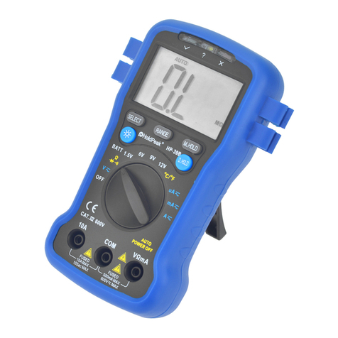
HoldPeak HP-37B User manual

HP-37B
DIGITAL MULTIMETER
OPERATOR’S MANUAL
1. Overview
The multimeter is characterized at slim size, portable, stable performance and
anti-droppin
g
capacit
y
.Usin
g
31/2di
g
its LCD monitor with character 28mm
hi
g
h, the
y
offer clear readin
g
s. With overall circuitr
y
desi
g
ncenterin
g
on
lar
g
e-scale IC
A
/D converters in con
j
unction and over-load protection circuit,
the meters
g
ive excellent performance and exquisite makin
g
as a hand
y
utilit
y
instrument.
The meters can be used to measure DC &
A
Cvolta
g
e, DC &
A
Ccurrent,
resistance, capacitor, temperature, batter
y
test, Non Contact
A
CVolta
g
e
(
NCV
)
detection, positive diode volta
g
e fall and audible continuit
y
.
2. Panel La
y
out
1Test lead fixture: Fix the test lead.
2CDS sensor: The CDS sensor can reaction to the ambient bri
g
htness
ran
g
e, then automaticall
y
control the LCD backli
g
ht to li
g
hten or
g
oout.
3NCV detection area: Non Contact
A
CVolta
g
e
(
NCV
)
detection area.
4NCV red li
g
ht: Non Contact
A
CVolta
g
e
(
NCV
)
detection red li
g
ht.
5NCV
g
reen li
g
ht: Non Contact
A
CVolta
g
e
(
NCV
)
detection
g
reen li
g
ht.
6LCD displa
y
:31/2di
g
its LCD displa
y
.
7HOLD ke
y
:Pressthe“HOLD”ke
y
to lock displa
y
value, and the “DH”
si
g
n will appear on the displa
y
,pressita
g
ain to exit.
8NCV Ke
y
:Pressthe“NCV”ke
y
, the meter enters Non Contact
A
C
Volta
g
e
(
NCV
)
detection, the NCV
g
reen LED li
g
ht will li
g
ht up, and the
“NCV”si
g
n will appear on the displa
y
,pressita
g
ain to exit.
9Rotar
y
Switch: Use this switch to select functions and ran
g
es.
10 COM: COM and Temperature “
-
” Input Jac
k
11 10A: 10
A
Input Jac
k
12 VΩmA: V/mA/BATT/20uF/ and Temperature “+” Input Jac
k
13 Crust of meter
14 Protective casin
g
3. Safety Information
3-1 The meter is desi
g
ned accordin
g
to IEC-1010 concernin
g
electronic
measurin
g
instruments with an over-volta
g
ecate
g
or
y
600V
(
CA
T
Ⅲ
)
and
pollution 2.
3-2 Follow all safet
y
and operatin
g
instructions to ensure that the meter is used
safel
y
and is kept in
g
ood operatin
g
condition.
3-3 safet
y
s
y
mbols:
Important safet
y
information, refer to the operatin
g
manual.
Dan
g
erous volta
g
ema
y
be presence.
Double insulation (protection Class II)
4. Special Cautions for Operation
4-1 The meters can be safe onl
y
accordin
g
to standard procedures when used
in con
j
unctions with the supplied test leads. To replace dama
g
ed test leads
with onl
y
the same model or same electric specifications.
4-2Toavidris
k
of electric shock, do not use the meters before the cover is in
place.
4-3 The ran
g
eswitchshouldberi
g
ht position for the testin
g
.
4-4 To avoid electric shock and dama
g
in
g
the instruments, the input si
g
nals are
forbidden to exceed the specified limits.
4-5 When measurin
g
TV set or switched power, attention should be paid to the
possible pulses that ma
y
brin
g
destruction to the circuit.
4-6 Ran
g
e switch position is forbidden to be chan
g
ed at random durin
g
measurement.
4-7 Take caution a
g
ainst shock in the course of measurin
g
volta
g
ehi
g
her than
DC 60V &
A
C30V.
4-8 Protection fuse should be replaced onl
y
with same t
y
pe and same
specification.
4-9
A
fter operation is finished, set function switch at OFF ran
g
etosavebatter
y
power.
4-10 If the meter is without usa
g
eforlon
g
time, take out batter
y
to avoid
dama
g
eb
y
batter
y
leaka
g
e.
5. GENERAL SPECIFICATIONS
5-1 Max Volta
g
e between input terminal and Earth Ground: CAT Ⅲ600V
5-2 Over-ran
g
e Indication: displa
y
“1”or“-1”forthesi
g
nificant di
g
it.
5-3
A
utomatic displa
y
of ne
g
ative polarit
y
“-” .
5-4 Low Batter
y
Indication: “ ”displa
y
ed.
5-5 Displa
y
:31/2di
g
it LCD with a max. readin
g
of 1999.
5-6 Manual ran
g
e control
5-7
A
uto Power Off: The meter will switch to standb
y
mode when power on
after approx. 30 minutes. Rotate the rotar
y
switch to OFF position, then
power on to exit standb
y
mode.
5-8
A
uto LCD backli
g
ht
5-9 Fuse protection: 200mA/250V PPTC Resettable Fuse
5-10 Power suppl
y
:9Vbatter
y
(
6F22 or NEDA 1604
)
5-11 Operatin
g
Temp.: 0℃to 40℃
(
relative humidit
y
<85%
)
5-12 Stora
g
e Temp.:-10℃to 50℃
((
relative humidit
y
<85%
)
5-13 Guaranteed precision Temp.: 23±5℃
(
relative humidit
y
<70%
)
5-14 Dimension: 150x106x36mm
5-15 Wei
g
ht: approx. 250
g
(
includin
g
batter
y)
6. Testin
g
Specifications
A
ccurac
y
is specified for a period of
y
ear after calibration and at 18℃to 28℃
(
64℉to 82℉
)
with relative humidit
y
to 70%.
6-1 DC
V
olta
g
e
Ran
g
e Resolution Accurac
y
2V 1mV
±
(
0.5% of rd
g
+2di
g
its
)
20V 10mV
200V 100mV
600V 1V ±
(
0.8% of rd
g
+2di
g
its
)
-- Impedance: 1MΩ
-- Overload protection: 600V DC or
A
Crms
6-2
A
C
V
olta
g
e
Ran
g
e Resolution Accurac
y
200V 100mV ±
(
1.2% of rd
g
+3di
g
its
)
600V 1V
-- Impedance: 1MΩ
-- Overload protection: 600V DC or
A
Crms
-- Frequenc
y
Ran
g
e: 40 to 400Hz
-- Response: avera
g
e, calibrated in rms of sine wave
6-3 DC Current
Ran
g
e Resolution Accurac
y
200mA 100μA±
(
1.2% of rd
g
+2di
g
its
)
10A 10mA ±
(
2.0% of rd
g
+3di
g
its
)
-- Overload protection: 200mA/250V PPTC Resettable Fuse
Note: 10
A
range is not fused, 10
A
up to 10 seconds
6-4
A
C Current
Ran
g
e Resolution Accurac
y
200mA 100μA±
(
1.5% of rd
g
+3di
g
its
)
10A 10mA ±
(
2.5% of rd
g
+5di
g
its
)
-- Overload protection: 200mA/250V PPTC Resettable Fuse
Note: 10
A
range is not fused, 10
A
up to 10 seconds
-- Frequenc
y
Ran
g
e: 40 to 400Hz
-- Response: avera
g
e, calibrated in rms of sine wave
6-5 Resistance
Ran
g
e Resolution Accurac
y
200Ω0.1Ω±
(
1.0% of rd
g
+3di
g
its
)
2kΩ1Ω±
(
1.0% of rd
g
+2di
g
its
)
200kΩ100Ω
2MΩ1kΩ±
(
1.5% of rd
g
+3di
g
its
)
-- Overload protection: 250
V
DC or
A
Crms
6-6 Capacitance
Ran
g
e Accurac
y
Resolution
20µF ±
(
2.5% of rd
g
+5di
g
its
)
10nF
-- Overload protection: 200mA/250V PPTC Resettable Fuse
6-7 Temperature
Ran
g
e Accurac
y
Resolution
℃-20~150℃±
(
3℃+ 1di
g
it
)
1℃
150~1000℃±
(
3% of rd
g
+2di
g
its
)
-- NiCr-NiSi K-t
y
pe sensor
-- Overload protection: 200mA/250V PPTC Resettable Fuse
6-8 Batter
y
test
Ran
g
e
A
ccurac
y
Load current Resolution
±
(
5.0% of rd
g
+5di
g
its
)
A
pprox. 50mA 1mV
A
pprox. 10mA 10mV
-- Overload protection: 200mA/250V PPTC Resettable Fuse
6-9 Diode and
A
udible continuit
y
test
Ran
g
e Description Test Condition
Displa
y
read approximatel
y
forward volta
g
eofdiode
Forward DC current
approx. 1m
A
Reversed DC volta
g
e
approx. 3V
Built-in buzzer sounds if
resistance is less than 50Ω
Open circuit volta
g
e
approx. 3V
Overload protection: 250V DC or
A
Crms
6-10 Non Contact
A
C
V
olta
g
e
(
NCV
)
detection
Test volta
g
eran
g
e: 90V~1000V
A
Crms
TheNCVredLEDli
g
ht and
g
reen LED li
g
ht will li
g
ht up alternatel
y
to
g
ether
with sound.

7. OPERATING INSTRUCTIONS
7-1 Attention before operation
7-1-1 Check battery. When the battery voltage drop below proper operation
range, the “ ” symbol will appear on the LCD display and the battery need to
changed.
7-1-2 Pa
y
attention to the “ ” besides the input
j
ack which shows that the
input volta
g
e or current should be within the specified value.
7-1-3 The ran
g
e switch should be positioned to desired ran
g
e for measurement
before operation.
7-2 Measuring DC
V
oltage
7-2-1 Connect the black test lead to COM
j
ack and the red to VΩmA
j
ack.
7-2-2 Set the rotar
y
switch at the desired “V”ran
g
eposition.
7-2-3 Connect test leads across the source or load under measurement.
7-2-4 You can
g
et readin
g
from LCD. The polarit
y
of the red lead connection
will be indicated alon
g
with the DC volta
g
e value.
NOTE:
1. When the value scale to be measured is unknown beforehand, set the range
selector at the highest position.
2. When onl
y
the figure
“
1” or
“
-1” i
s
displayed, it indicate
s
over-range situation and the
higher range ha
s
to be selected.
3. “ ” means you can’t input the voltage more than 600V, it’s possible to show
higher voltage, but it may destroy the inner circuit or pose a shock.
4. Be cautious a
g
ainst shock when measurin
g
hi
g
hVolta
g
e.
7-3 Measuring
A
C
V
oltage
7-3-1 Connect the black test lead to COM
j
ack and the red to VΩmA
j
ack.
7-3-2 Set the rotar
y
switch at the desired “V”ran
g
eposition.
7-3-3 Connect test leads across the source or load under measurement.
7-3-4 You can
g
et readin
g
from LCD. The polarit
y
of the red lead connection
will be indicated alon
g
with the DC volta
g
e value.
NOTE:
1. When the value scale to be measured is unknown beforehand, set the range
selector at the highest position.
2. When onl
y
the figure
“
1” or
“
-1” i
s
displayed, it indicate
s
over-range situation and the
higher range ha
s
to be selected.
3. “ ” means you can’t input the voltage more than 600V, it’s possible to show
higher voltage, but it may destroy the inner circuit or pose a shock.
4. Be cautious a
g
ainst shock when measurin
g
hi
g
hVolta
g
e.
7-4 Measuring DC Current
7-4-1 Connect the black test lead to COM
j
ack and the red to the
V
ΩmA
j
ack
for a maximum 200mA current , for a maximum 10A current, move the red lead
to the 10A
j
ack.
7-4-2 Set the rotar
y
switch at the desired “A”ran
g
eposition.
7-4-3 Connect test leads in series with the load under measurement.
7-4-4 You can
g
et readin
g
from LCD. The polarit
y
of the red lead connection
will be indicated alon
g
with the DC current value.
NOTE:
1. When the value scale to be measured is unknown beforehand, set the ran
g
e
selector at the hi
g
hest position.
2. When onl
y
the fi
g
ure
“
1” or
“
-1” is displa
y
ed, it indicates over-ran
g
esituation
and the hi
g
her ran
g
e has to be selected.
3. “ ” means the socket mA’s maximum current is 200mA and 10A’s
maximum current is 10A, over 200m
A
current can be protected b
y
the PPTC
resettable fuse, but the 10
A
ran
g
eisnotfused.
4. On the 10
A
ran
g
e, the measurin
g
time should be less than 10 seconds to
prevent precision from affectin
g
b
y
circuit heatin
g
.
7-5 Measuring
A
C Current
7-5-1 Connect the black test lead to COM
j
ack and the red to the
V
ΩmA
j
ack
for a maximum 200mA current , for a maximum 10A current, move the red lead
to the 10A
j
ack.
7-5-2 Set the rotar
y
switch at the desired “A”ran
g
e position.
7-5-3 Connect test leads in series with the load under measurement.
7-5-4 You can
g
et readin
g
from LCD. The polarit
y
of the red lead connection
will be indicated alon
g
with the DC current value.
NOTE:
1. When the value scale to be measured is unknown beforehand, set the ran
g
e
selector at the hi
g
hest position.
2. When onl
y
the fi
g
ure
“
1” or
“
-1” is displa
y
ed, it indicates over-ran
g
esituation
and the hi
g
her ran
g
e has to be selected.
3. “ ” means the socket mA’s maximum current is 200mA and 10A’s
maximum current is 10A, over 200m
A
current can be protected b
y
the PPTC
resettable fuse, but the 10
A
ran
g
eisnotfused.
4. On the 10
A
ran
g
e, the measurin
g
time should be less than 10 seconds to
prevent precision from affectin
g
b
y
circuit heatin
g
.
7-6 Measuring Resistance
7-6-1 Connect the black test lead to COM
j
ack and the red to VΩmA
j
ack.
7-6-2 Set the rotar
y
switch at the desired “Ω”ran
g
eposition.
7-6-3 Connect test leads across the resistance under measurement.
7-6-4 You can
g
et readin
g
from LCD.
NOTE: Max. input overload: 250V rms<10sec
1. When onl
y
the fi
g
ure “1” or “-1” is displa
y
ed, it indicates over-ran
g
esituation
and the hi
g
her ran
g
e has to be selected.
2. For measurin
g
resistance above 1MΩ, the mete ma
y
take a few seconds to
g
et stable readin
g
.
3. When the input is not connected, i.e. at open circuit, the fi
g
ure “1” or “-1” will
be displa
y
ed for the over-ran
g
e condition.
4. When checkin
g
in-circuit resistance, be sure the circuit under test has all
power removed and that all capacitors have been dischar
g
ed full
y
.
7-7 Measuring Capacitance
7-7-1 Connect the black test lead to COM
j
ack and the red to
V
ΩmA
j
ack.
7-7-2 Set the rotar
y
switch at the desired “20uF”ran
g
eposition.
7-7-3 Connect test leads across the capacitance under measurement.
7-7-4 You can
g
et readin
g
from LCD.
NOTE: Capacitors should be dischar
g
ed before bein
g
tested.
7-8 Measuring Temperature
7-8-1 Connect the black banana plu
g
of the sensor to COM
j
ack and the
red banana plu
g
to the
V
ΩmA
j
ack.
7-8-2 Set the rotary switch at the desired “ ” range position.
7-8-3 Put the sensor probe into the temperature field under measurement.
7-8-4 You can
g
et readin
g
from LCD.
NOTE:
1. The accessor
y
of the meter WRNM-010 t
y
pe contact thermocouple limit
temperature is 250
(
300 shortl
y)
, please use special probe for test
hi
g
her temperature.
2. Please don't chan
g
e the thermocouple at will, otherwise we can't
g
uarantee
to measure accurac
y
.
3. Please don’t importin
g
the volta
g
e in the temperature function.
7-9 Battery Testing
7-9-1 Connect the black test lead to COM
j
ack and the red to
V
ΩmA
j
ack.
7-9-2 Set the rotary switch at the desired “ ”or“ ” range position to
test 1.5
V
or 9V batter
y
.
7-9-3 Connect test leads across the source or load under measurement.
7-9-4 You can
g
et readin
g
from LCD.
7-10 Diode &
A
udible continuity Testing
7-10-1 Connect the black test lead to COM
j
ack and the red to
V
ΩmA
j
ack.
7-10-2 Set the rotary switch at the “ ” range position.
7-10-3 On diode ran
g
e, connect the test leads across the diode under
measurement, displa
y
shows the approx. forward volta
g
e of this diode.
7-10-4 On
A
udible continuit
y
ran
g
e, connect the test leads to two point
of circuit, if the resistance is lower than approx. 50Ω, the buzzer sounds.
NOTE: Make sure the power is cut off and all capacitors need to be dischar
g
ed
under this measurement.
7-11 Non Contact
A
C
V
oltage detection
7-11-1 Power on the meter, on an
y
ran
g
e, press the “NCV”ke
y
,themeter
enters Non Contact
A
CVolta
g
e
(
NCV
)
detection, the NCV
g
reen LED li
g
ht will
li
g
ht up, and the “NCV”si
g
n will appear on the displa
y
.
7-11-2 Hold the Meter so that the mater’s top is verticall
y
and horizontall
y
centered and contactin
g
the conductor, when the live volta
g
e≥90V
A
C
rms, the NCV red LED li
g
ht and
g
reen LED li
g
ht will li
g
ht up alternatel
y
to
g
ether with sound.
NOTE:
1. Even without LED indication, the volta
g
ema
y
still exist. Do not rel
y
on
non-contact volta
g
e detector to determine the presence of volta
g
ewire.
Detection operation ma
y
be sub
j
ect to socket desi
g
n, insulation thickness and
different t
y
pe and other factors.
2. When the meter input terminals presence volta
g
e, due to the influence of
presence volta
g
e, volta
g
esensin
g
indicator ma
y
also be bri
g
ht.
3. Keep the meter awa
y
from electrical noise sources durin
g
the tests, i.e.,
florescent li
g
hts, dimmable li
g
hts, motors, etc.. These sources can tri
gg
er
Non-Contact
A
CVolta
g
e detection function and invalidate the test.
8. Battery replacement
1) When the battery voltage drop below proper operation range the " "
s
y
mbol will appear on the LCD displa
y
and the batter
y
need to chan
g
ed.
2
)
Before chan
g
in
g
the batter
y
, set the selector switch to “OFF”position.
Open the cover of the batter
y
cabinet b
y
a screwdriver.
3
)
Replace the old batter
y
withthesamet
y
pe batter
y
(
9V 6F22 or NEDA
1604
)
.
4
)
Close the cover of the batter
y
cabinet and fasten the screw.
9. Maintenance
9-1 Before attemptin
g
to remove the batter
y
door or open the case, be sure
that test leads have been disconnected from measurement circuit top avoid
electric shock hazard.
9-2 You must replace the test leads if the lead is exposed, and should adopt
the leads with the same specifications as ori
g
in.
9-3 Use onl
y
moist fabric or small amount of deter
g
ent but not chemical
solution for cleanin
g
.
9-4 Do not use the meter before the back cover is properl
y
closed and screw
secured. Upon an
y
abnormalit
y
, stop operation immediatel
y
and send the
meter for maintenance.
9-5 Please take out the batter
y
when not usin
g
for a lon
g
time.
10.
A
ccessories
[1] Test Leads: electric ratin
g
1000V 10A
[2] “K” t
y
pe thermocouple sensor probe
[3] Operator’s Manual
Table of contents
Other HoldPeak Multimeter manuals

HoldPeak
HoldPeak 760A Installation manual

HoldPeak
HoldPeak 760J Installation manual

HoldPeak
HoldPeak 6208 User manual

HoldPeak
HoldPeak 39K User manual

HoldPeak
HoldPeak 870N User manual

HoldPeak
HoldPeak 860N User manual

HoldPeak
HoldPeak 770A User manual

HoldPeak
HoldPeak 39B User manual

HoldPeak
HoldPeak 90B User manual

HoldPeak
HoldPeak 39B User manual

HoldPeak
HoldPeak HP-37A User manual

HoldPeak
HoldPeak 870E Installation manual

HoldPeak
HoldPeak 36 k User manual

HoldPeak
HoldPeak HP-770H User manual

HoldPeak
HoldPeak 860D User manual

HoldPeak
HoldPeak 770G User manual

HoldPeak
HoldPeak HP-36C User manual

HoldPeak
HoldPeak HP-760E User manual

HoldPeak
HoldPeak 770HD User manual

HoldPeak
HoldPeak 90F User manual