Finest 401 User manual

Resistance
FINE INSTRUMENTS CORPORATION
B11, A-DONG, SMART VALLEY , SONGDOMIRAE-RO 30, YEONSU-GU, INCHEON, KOREA
- TEL: (82-32) 837-5777 - FAX: (82-32) 837-5776
- Internet: or www.finest. co.kr
© Copyright 2015 Fine Instruments Corp. All right reserved.
Specifications subject to change without notice.
Litho in Korea.
a world leader in test & measurement
Model 401
USER’S
MANUAL
FINE INSTRUMENTS CORPORATION

SOURCES LIKE SMALL HAND-HELD RADIO
TRANSCEIVERS, FIXED STATION RADIO
AND TELEVISION TRANSMITTERS, VEHICLE
RADIO TRANSMITTERS AND CELLULAR
PHONES GENERATE ELECT ROMAGNETIC
RADIATION THAT MAY INDUCE VOLTAGES
IN THE TEST LEADS OF THE MULTIMETER.
IN SUCH CASES THE ACCURACY OF THE
MULTIMETER CANNOT BE GUARANTEED
DUETO PHYSICAL REASONS.
CONTENTS
!GNINRAW
1
2
SAFETY INFORMATION
.1
5
CONTROL AND INDICATORS
2
8
METER FUNCTIONS AND SPECIAL FEATURES
.3
3-1. AC/DC Voltage 8
3-2. DC milli-Voltage 9
3-3. Resistance 01
11Insulation Test.4-3
.5-3
14
SPECIFICATIONS
.4
31Sleep Mode


54
CAUTION
Disconnect the test leads from the points before changing functions.
Disconnect circuit power and discharge all high voltage capacitors before testing
resistance, or continuity.
Always set the meter tothe highest range and work downward for an unknown
value in the manual ranging mode.
2. CONTROL AND INDICATORS
1
8
9
7
56
4
3
2

0
0.05M
0.1M
1M
10M
100M
1G 2G
MkG
mV
76
LCD display with 28 segments bar-graph.
Press this button to initiate an insulation test in the
Insulation test mode.
Press this button to enter Test lock mode in the Insulation
test mode. is displayed on LCD in this mode.
Press again to release the lock.
Turn the power On or Off and select a test function.
Input terminal for insulation test, voltage and resistance
functions.
Common input terminal for all functions.
Switch between AC and DC.
Switch between Ω and .
Press this button for 2 seconds to enable / disable lights.
The backlight automatically turns off after 2 minutes.
Press this button repeatedly to cycle through manual ranges.
Press this button for 2 seconds to return to the auto ranging
mode. is displayed on LCD only during auto
ranging mode.
Press this button to activate HOLD for capturing the current
displayed value. Press this button again to activate
AUTO HOLD for automatically capturing a stable reading,
beeping to acknowledge, and holding it on the LCD. Press
again to return to normal operation.
Indicates autoranging.
Indicates direct current or alternating current is selected.
Indicates Negative Polarity.
Indicates an out of range value in the Insulation test mode.
High voltage symbol.
1. LCD display
2.
3.
4. Selector
5. V
6. COM
7.
8.
9.
10.
11.
12.
13.
14.
Analog bar-graph with scale(Available in the Insulation mode only).
Low battery alert.
This symbol appears when the battery is too low to perform
DMM functions.
This symbol appears along with when the battery is
too low to perform Insulation test.
annunciator indicates the HOLD function is selected
and annunciators indicate the Autohold function
is selected.
Indicates the Continuity test function is selected.
Indicates the function being selected and/or the appropriate
measurement units.
Indicates an insulation test is performed.
Indicates an insulation test is locked on.
15.
16.
17.
18.
19.
20.
21.
LOCK
TEST
SEL
AUTOHOLD
0
0.05M
0.1M
mV ...
19
2021
10
11
12
13
14
16
17
15
18
RANGE
98
3. METER FUNCTIONS AND SPECIAL FEATURES
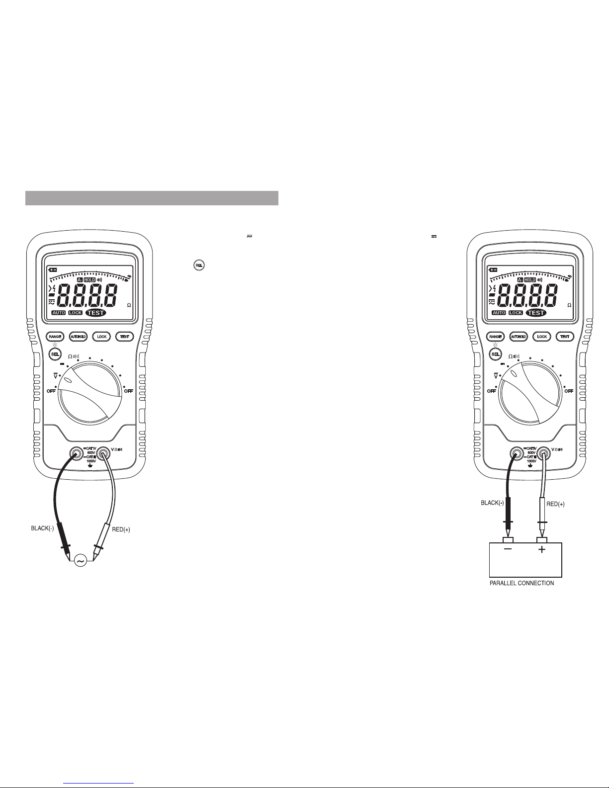
3-1. AC / DC Voltage
1. Set the rotary selector to Vposition.
3. Insert red lead into V terminal and
black lead into COM terminal.
2. The meter defaults at AC.
Press button momentarily to
toggle between AC and DC.
4. Connect black probe to ground and
red probe to the side of the circuit
closest to the power source.
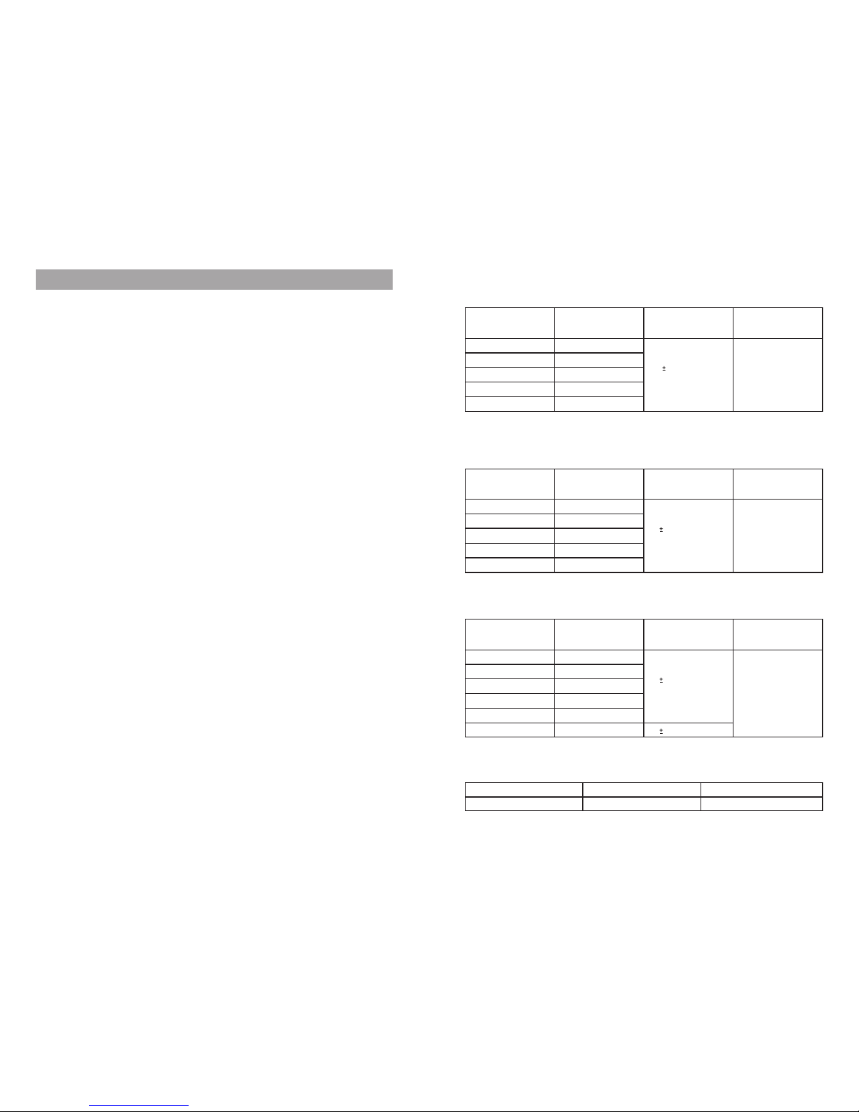
3-2. DC milli-Voltage
1. Set the rotary selector to
position.
2. Insert red lead into V terminal and
black lead into COM terminal.
3. Connect black probe to negative
side of the circuit and red probe to
positive side of the circuit coming
from the power source.
SEL
mV
RANGE
COM
V
CAT IV
600V
CAT III
1000V
INSULATION
AUTOHOLD
mV
100V
250V
500V
1000V
SEL
0
0.05M
0.1M
1M
10M
100M
1G 2G
MkG
m
V
TESTLOCK RANGE
COM
V
CAT IV
600V
CAT III
1000V
INSULATION
AUTOHOLD
mV
100V
250V
500V
1000V
SEL
0
0.05M
0.1M
1M
10M
100M
1G 2G
MkG
m
V
TESTLOCK

1110
RANGE
COM
V
CAT IV
600V
CAT III
1000V
INSULATION
AUTOHOLD
mV
100V
250V
500V
1000V
SEL
0
0.05M
0.1M
1M
10M
100M
1G 2G
MkG
m
V
TESTLOCK RANGE
COM
V
CAT IV
600V
CAT III
1000V
INSULATION
AUTOHOLD
mV
100V
250V
500V
1000V
SEL
0
0.05M
0.1M
1M
10M
100M
1G 2G
MkG
m
V
TESTLOCK
1.
2.
Insert test leads into V and COM
input terminals.
3-4. Insulation Test
CAUTION
Turn off power and discharge all
capacitors on circuit to be tested before
attempting Insulation test.
Set the rotary selector tothe desired
test voltage position. A battery load
check is initiated when the switch is
moved tothis position. If the battery
fails, andappear on the
display.
In this case, Insulation tests cannot
be performed until the batteries are
replaced.
3-3. Resistance
1. Set the rotary selector to Ωposition.
is displayed.
The meter defaults at Ω.
3. Insert black lead into COM terminal
and red lead into Ωterminal.
4. Touch the probes across the
resistance or circuit to be tested.
CAUTION
Turn off power and discharge all
capacitors on circuit to be tested before
attempting incircuit resistance
measurements. Accurate measurement
is not possible if external or residual
voltage is present.
If the resistance of the device is below
40 Ω, there is a continuity beep tone.
If the resistance of the device is more than
40 Ω, there is no beep tone.
This is useful for checking wiring
connections and operation of switches.
2. Press button momentarily to
select .
SEL

1312
3.
4.
5. Release the button before disconnecting the probes from the
circuit under test. Then, the circuit will automatically be discharged through
the meter.
NOTE : When the button is pressed before the button,
the test remains active until the or button is
pressed again.
Connect the lead probes to the circuit under test. The meter automatically
detects if the circuit is energized.
The display shows until you press and a valid insulation
resistance reading is obtained.
Press and hold button to start the test. The LCD shows (high
voltage warning) symbol along with the resistance in MΩor GΩ.
The symbol will be displayed on the LCD until the button is
released. The meter displays symbol along with the maximum resistance
for the range when the resistance is higher than the maximum display range.
LOCK
LOCK
TEST
TEST
TEST
TEST
TEST
TEST
The meter automatically enters “Sleep mode” after 30 minutes non-use. The meter
comes out of the Sleep mode when a button is pressed.
The Sleep mode is always disabled in the Hold or Autohold mode and when
performing an insulation test.
3-5. Sleep Mode
14 15
Electric Specifications
AC Voltage
DC Voltage
Input Impedance (nominal) : 10 MΩ, < 100pF
Response : Average RMS
Input Impedance (nominal) : 10 MΩ, < 100pF
Range Accuracy
(50 Hz ~ 60 Hz)
400.0 mV 0.1 mV
4.000 V 0.001 V
40.00 V 0.01 V
400.0 V 0.1 V
Resolution
1000 V 1 V
1000 Vrms
Overload
Protection
(1.0 % + 8 dgts)
Range Accuracy
400.0 mV 0.1 mV
4.000 V 0.001 V
40.00 V 0.01 V
400.0 V 0.1 V
Resolution
1000 V 1 V
1000 Vrms
Overload
Protection
(0.8 % + 10 dgts)
Input Impedance (nominal) : 10 MΩ, < 100pF
Range
Overload Protection Open Circuit Voltage Threshold(Appx.)
Accuracy
400.0
Ω
0.1
Ω
4.000 k
Ω
0.001 k
Ω
40.00 k
Ω
0.01 k
Ω
400.0 k
Ω
0.1 k
Ω
Resolution
4.000 M
Ω
0.001 M
Ω
40.0 M
Ω
400 Vrms < 0.44 V < 40
Ω
0.01 M
Ω
400 Vrms
Overload
Protection
(1.0 % + 5 dgts)
(1.5 % + 10 dgts)
Resistance
Continuity Test
Operating Temperature
Storage Temperature
Temperature Coefficient
Relative Humidity
Altitude
Safety
Overload protection
Certifications
Battery
Battery Life
Pollution Degree
Dimensions
Weight
4. SPECIFICATIONS
General Specifications
: 0 °C to 50 °C (32 °F to 122 °F) at <75% R.H.
: -20 °C to 60 °C (-4 °F to 140 °F) at <80% R.H.
: nominal 0.15 x (specified accuracy) / °C @
<18 °C or >28 °C (<64 °F or >82 °F), or
otherwise specified
: 0% to 95% @ 10 °C to 30 °C(50 °F to 86 °F)
0% to 75% @ 30 °C to 40 °C(86 °F to 104 °F)
0% to 40% @ 40 °C to 50 °C(104 °F to 122 °F)
: Operating – up to 2000m
Storage – 10000m
: Complies with UL61010-1: 3rd Edition, CAN /
CSA-C22.2 No. 61010-1-12 : 3rd Edition, IEC /
EN 61010-1 : 2010 ; Overload protaction CAT IV
600V and CAT III 1000V
: CAT IV 600V and CAT III 1000V
: UL Listed and CE marked
: 6 x AAA batteries (NEDA 24A or IEC LR03)
: Meter use – 1000 hours
Insulation Test use – Meter can perform at least
1000 tests with alkaline batteries at room
temperature. These standard tests of
1000 V into 1 MΩwith a duty cycle of 5
seconds on and 25 seconds off.
: 2
: 178mm x 89mm x 48mm
: 440g

16
Short-Circuit Test Current (nominal) : 0.5 mA
Auto Discharge : Discharge time <1 sec. for C ≤ 1 uF
Minimum Measurement : 0.1 M
Ω
Output Voltage Resolution Accuracy
100 V
250 V
500 V
1000 V
0.01 ~ 20.00 M
Ω
20.0 ~ 100.0 M
Ω
0.01 ~ 20.00 M
Ω
20.0 ~ 200.0 M
Ω
0.01 ~ 20.00 M
Ω
20.0 ~ 200.0 M
Ω
200 ~ 500 M
Ω
0.01 ~ 20.00 M
Ω
20.0 ~ 200.0 M
Ω
200 ~ 2000 M
Ω
Display Range
0.01 M
Ω
0.1 M
Ω
0.01 M
Ω
0.1 M
Ω
0.01 M
Ω
0.1 M
Ω
1 M
Ω
0.01 M
Ω
0.1 M
Ω
1 M
Ω
Test Current
(3 % + 5)0.5 mA @ 100 K
Ω
0.5 mA @ 250 K
Ω
0.5 mA @ 500 K
Ω
0.5 mA @ 1 M
Ω
(3 % + 5)
Insulation Test
(3 % + 5)
(5 % + 5)
(3 % + 5)
(5 % + 5)
Table of contents


