Vytran PTR-200 Series User manual

Artisan Technology Group is your source for quality
new and certied-used/pre-owned equipment
• FAST SHIPPING AND
DELIVERY
• TENS OF THOUSANDS OF
IN-STOCK ITEMS
• EQUIPMENT DEMOS
• HUNDREDS OF
MANUFACTURERS
SUPPORTED
• LEASING/MONTHLY
RENTALS
• ITAR CERTIFIED
SECURE ASSET SOLUTIONS
SERVICE CENTER REPAIRS
Experienced engineers and technicians on staff
at our full-service, in-house repair center
WE BUY USED EQUIPMENT
Sell your excess, underutilized, and idle used equipment
We also offer credit for buy-backs and trade-ins
www.artisantg.com/WeBuyEquipment
REMOTE INSPECTION
Remotely inspect equipment before purchasing with
our interactive website at www.instraview.com
LOOKING FOR MORE INFORMATION?
Visit us on the web at www.artisantg.com for more
information on price quotations, drivers, technical
specications, manuals, and documentation
Contact us: (888) 88-SOURCE | sales@artisantg.com | www.artisantg.com
SM
View
Instra

RREEFFEERREENNCCEEGGUUIIDDEE
PTR-200-ARL
Artisan Technology Group - Quality Instrumentation ... Guaranteed | (888) 88-SOURCE | www.artisantg.com

PTR-200 Series Quick Reference Guide Version 1.2. Printed in the United States.
The contents of this manual and the associated software are the property of Vytran Corporation and are
copyrighted. Under the copyright laws, neither the documentation nor the software may be copied,
photocopied, reproduced, translated or reduced to any electronic medium or machine readable form, in
whole or part, without prior written consent of Vytran Corporation.
Copyright 1999 Vytran Corporation
1400 Campus Drive West
Morganville, NJ 07751 USA
Phone: 732-972-2880
800-421-8874
Fax: 732-972-6229
PTR-200-ARL Quick Reference Guide Version 1.2
Artisan Technology Group - Quality Instrumentation ... Guaranteed | (888) 88-SOURCE | www.artisantg.com

Setting Up The PTR-200 And Getting Started
Quick Reference Guide For The ARL Module
This quick reference guide will show you how to set up your PTR-200 and how to recoat and proof test an optical fiber.
The illustrations and descriptions refer to an ARL Module configured with the optional Integrated Module Controller
(Touch Screen Controller) and external vacuum pump. Please refer to the serial command list if operating directly from a
PC.
Accessory Parts Checklist
When unpacking the PTR-200 for the first time, check to make sure that you have the following accessories:
12.5V Power supply box with AC power cord
DC power cable to connect the external power supply to the unit
1/8" O.D. pressure supply tubing and fittings kit for compressed air hook-up
VYT-200-C Integrated Module Controller with interface cable (optional)
External vacuum pump with vacuum line (optional)
Tool kit containing: Recoat material, DSM Desotech 950-200
Cotton swabs
Lens tissue
5/64" Allen wrench
3/32" Allen wrench
.035" Allen wrench
External Power Supply and Cable
ARL Module with Integrated
Module Controller Attached
External Vacuum Pump
PTR-200-ARL Quick Reference Guide Version 1.2 Page 1
Artisan Technology Group - Quality Instrumentation ... Guaranteed | (888) 88-SOURCE | www.artisantg.com

Figure 1 - Back View of ARL Module
I. SETTING UP the PTR-200
A. The following steps will show you how to set up your PTR-200. (Refer to Fig.1)
1. Attach the Integrated Module Controller (VYT-200-C), by removing the four mounting screws and washers from the
back of the PTR-200. Place the PTR-200 and Controller on a flat work surface and secure the controller bracket to
the back of the PTR-200. Make sure the feet on the bottom of the bracket sit flush on the work surface. NOTE:
You can set the tension of the tilt display by adjusting the left- hand pivot screw. A 5/64" allen wrench is provided
in the tool kit.
2. Connect the interface cable from the bottom of the Controller to the back of the PTR-200.
3. An RS-232 serial input is provided for direct PC control. Note: The Integrated Module Controller and the PC
serial interface should not be connected simultaneously - possible damage to the controller could occur.
4. Connect the DC power cable from the external power supply to the back of the PTR-200. Plug in the power supply
(100-120 / 200-240 VAC).
5. Plug in the external vacuum pump. To connect the vacuum line, insert the silver quick connect fitting into the
lower fitting on the pump. Connect the other end of the tubing to the brass barbed fitting on the back of the
PTR-200. Connect the small "muffler" to the upper fitting of the vacuum pump.
6. The pneumatic gripper of the automated recoater requires a clean compressed air (or gas) supply of 80 to 120 psi.
Use the fittings kit provided to connect the 1/8" OD quick connect fitting into the supply source. Connect the 1/8"
OD pressure supply line between the source and the unit by pushing the tubing fully into the fittings.
PTR-200-ARL Quick Reference Guide Version 1.2 Page 2
Artisan Technology Group - Quality Instrumentation ... Guaranteed | (888) 88-SOURCE | www.artisantg.com

II. First Time Start-Up
Important! Read all Material Safety Data Sheet information for the recoat compound before proceeding.
When using the PTR-200 for the first time, follow these steps:
A. Fill the recoat bottle located inside the PTR-200. See Fig. 2
1. Make sure power to the PTR-200 is switched OFF.
2. Remove the front panel by removing eight (8) black socket head cap screws. A 3/32 allen wrench is provided
in the tool kit.
3. Unscrew the brown bottle in the left hand corner and carefully fill it with recoat material to 3/4 full.
Pour slowly so as not to introduce air bubbles into the material.
4. Screw the bottle back into place and replace the front panel of the PTR-200.
B. Power Up the PTR-200
1. Turn on the external power supply, the external vacuum pump (optional), and the PTR-200 (Fig. 1 #7). The system
will go through an initialization process which takes from 15-90 seconds.
2. After initialization, you will be prompted to "Press Start to Continue". Touch the highlighted area of the screen to
proceed to the Main Menu. Note: It may take 5-10 minutes for the controller to warm-up and achieve good display
contrast. If you still need to adjust the contrast once the controller has warmed up, select the "TOOLS" icon to
activate the up-down arrows on the controller panel. Each click of an arrow button will increment the contrast.
Figure 2 - ARL Module with
Front Panel Removed to Show
Interior Recoat Bottle
PTR-200-ARL Quick Reference Guide Version 1.2 Page 3
Artisan Technology Group - Quality Instrumentation ... Guaranteed | (888) 88-SOURCE | www.artisantg.com

C. Purge the Recoat Pump
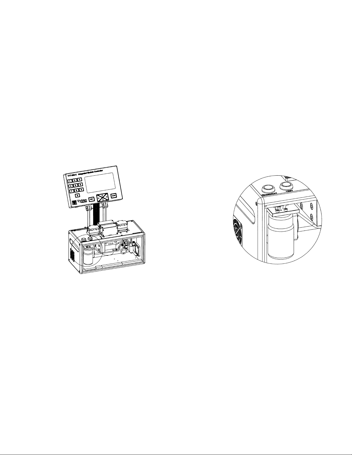
After filling or removing the internal recoat bottle, the recoat pump must be purged of air in order to eliminate any
bubbles in the final recoat. Five (5) purge cycles are required to pump material completely through the pump and
remove any air. Each purge cycle will draw material from the bottom of the recoat bottle through the red fill tube and
inject the material back into the top of the recoat bottle through the green purge tube. To run the purge cycles:
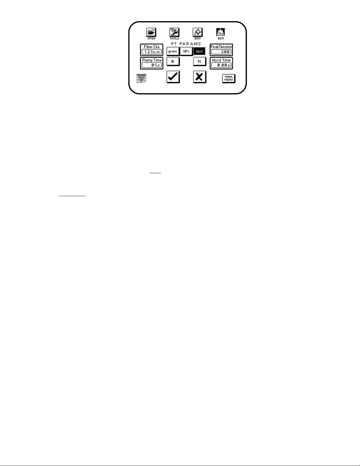
1. Select "TOOLS" from the Main Menu on the controller.
2. Highlight "PURGE" under the tools menu (see Fig. 3).
3. Type in "5" using the numeric keypad and touch the "" icon to proceed with the purge process. Note: If you
entered in an incorrect value, touch the "x" icon to cancel. Each purge cycle takes approximately 2-3 minutes.
The "" icon will remain highlighted until the process is completed.
D. Purge the Inject Tube
The recoat inject tube runs from the recoat pump to the recoat mold. Recoat material enters the mold at the center of
the back recoat mold plate. After purging the recoat pump, the inject tube must also be purged to remove trapped air.
Proceed as follows:
1. Make sure the recoat mold is opened. To open the mold, highlight "mold open" under the tools menu and select
the "" icon. Note: "Double click" the mold button to toggle between "mold open" and "mold close".
2. Make sure to have cotton swabs and cleaning solution (acetone or alcohol) available prior to proceeding. The
recoat material must be collected as it comes out of the mold injection port. Do not allow recoat material to run
down the face of the mold and under the mold plate.
3. From the "TOOLS" menu, select the "INJECT (µl)" icon, and, using the numeric keypad, enter in 50 for the
injection volume. You must inject 50µl three (3) times in order to purge air completely from the injection tube.
After keying in the inject value touch the "" icon to initiate the inject process. If an incorrect value was entered,
touch the "x" icon to cancel and re-enter the correct value. Make sure to collect the recoat material as it comes
out of the injection port. Note: The recoat injection pump can hold up to 100µl of recoat material. There will be
a delay of approximately one minute between the second and third injects while the pump refills with material.
4. After purging the inject tube, the recoat material should run freely from the mold without bubbles. If bubbles are
still present, run additional inject sequences.
5. Once purged, thoroughly clean both front and back mold plates with a cotton swab soaked in cleaning solution.
Note: Acetone is the preferred solution for cleaning the mold plates. Acetone cleans more thoroughly than
alcohol and will also soften and remove cured recoat material.
Figure 3 - Tools Menu.
PTR-200-ARL Quick Reference Guide Version 1.2 Page 4
Artisan Technology Group - Quality Instrumentation ... Guaranteed | (888) 88-SOURCE | www.artisantg.com

III. Using the System
A. Load the Fiber
1. If the recoat mold is not already opened, do so by using the "mold open" command under the tools menu.
2. Raise the tops on both the left and right fiber holding blocks. Note: As long as one of the fiber holding block tops
is raised vacuum will be applied to the fiber guides. Although vacuum is not required, it does assist in locating the
fibers in the fiber holding blocks.
3. Position the fiber such that the exposed section to be recoated is centered in the mold.
4. Close both fiber holding block tops.
Figure 4: Edit Recoat Menu
B. Recoat
1. Check the recoat parameters by selecting the edit recoat icon. The parameters are defined as follows:
Quantity: The volume of recoat material in microliters (µl) injected into the mold.
Rate: The speed at which recoat material is injected into the mold in microliters per second (µl/s).
The maximum inject rate is 1.8µl/s
Delay Time: The amount of time in seconds between the end of the injection process and the start of the
curing process (lamps on).
Lamp Time: The amount of time in seconds that the curing lamps are on.
Recommended values are preset at time of shipment. Typical values for a 30mm long recoat (strip length) and an ARL
Module with a 260mm mold are listed below:
Quantity (l): 1.2
Rate (l/s): 0.2
Delay time: 1 second
Lamp time: 20 seconds
Only the inject quantity should need to be adjusted for the length of recoat required. The quantity required depends
on the diameter of the mold, the diameter of the fiber, and the length of the recoat. Table 1. gives the approximate
injection quantity in l for different length recoats and different mold sizes. A 125m fiber diameter is assumed for
all mold sizes except 160m, which is calculated based on an 80m fiber diameter. The formula for calculating
injection volumes is also given.
PTR-200-ARL Quick Reference Guide Version 1.2 Page 5
Artisan Technology Group - Quality Instrumentation ... Guaranteed | (888) 88-SOURCE | www.artisantg.com

2. To change the recoat quantity, highlight "Quantity(l)", type in the desired value, and select "" to accept the
value or "x" to cancel.
3. Select "MAIN MENU" to return to the main process screen.
4. Select "RECOAT" to initiate the recoat process.
Table 1. Approximate injection quantity in microliters (l) required for different length recoats.
The volume of recoat material required can be calculated as follows:
Diameters and length of the recoat in mm.
Select the Correct Mold Size for Your ARL Module
160 m 260 m 280 m 430 m 900 m
5 mm 0.07 0.20 0.25 0.86 4.00
10 mm 0.13 0.40 0.50 1.72 8.00
15 mm 0.20 0.60 0.75 2.58 12.00
20 mm 0.27 0.80 1.00 3.44 16.00
25 mm 0.34 1.00 1.25 4.30 20.00
30 mm 0.40 1.20 1.50 5.16 24.00
40 mm 0.54 1.60 2.00 6.88 32.00
Recoat
length
Vol (
l)
= ________ - ________ - length of recoat
4 4
()
π
D2mold
π
D2fiber l
PTR-200-ARL Quick Reference Guide Version 1.2 Page 6
Artisan Technology Group - Quality Instrumentation ... Guaranteed | (888) 88-SOURCE | www.artisantg.com

Figure 5: Edit Proof Test Menu
C. Proof Test
1. Check the Proof Test parameters by selecting the edit proof test icon. The parameters are defined as follows:
Fiber Dia: The diameter of the fiber in microns (m). This diameter is required to calculate the units of kpsi and
GPa. Note: Enter the diameter of the fiber, not the diameter of the coating.
Peak Tension: The tension to which the fiber is to be proof tested. The units of measure corresponds to the
highlighted display (grams, GPa, kpsi, pounds, or Newtons).
Ramp Time: The approximate time in seconds required to reach the peak tension.
Hold Time: The amount of time in seconds that the peak load is held for.
Typical values for proof testing standard single mode fiber (eg. Corning SMF-28) are:
Units: kpsi
Fiber Dia: 125 m
Peak Tension: 100
Ramp Time: 5 seconds
Hold Time: 0 seconds
2. To change a parameter, highlight the desired parameter, type in the desired value, and select "" to accept the
value or "x" to cancel.
3. Select "MAIN MENU" to return to the main process screen.
4. Select "PROOF TEST" to initiate the proof test process.
PTR-200-ARL Quick Reference Guide Version 1.2 Page 7
Artisan Technology Group - Quality Instrumentation ... Guaranteed | (888) 88-SOURCE | www.artisantg.com

IV. Shutting Down
A. Store the Unit
To keep the recoat mold clean and to prevent possible curing of the recoat material in the inject port, we recommend
"storing" the mold as follows:
1. Clean both front and back recoat mold plates thoroughly with a soft cotton swab wetted with acetone.
2. Place lens tissue or a soft wipe between the mold plates. Use several sheets or fold several times to get
multiple layers.
3. Select the "TOOLS" icon and highlight the "STORE" command. Select "" to close the mold and release the
pneumatic pressure to the gripper.
4. Turn off the vacuum pump (if provided).
5. Turn off the power switch on the back of the PTR-200.
6. Turn off the power supply.
PTR-200-ARL Quick Reference Guide Version 1.2 Page 8
Artisan Technology Group - Quality Instrumentation ... Guaranteed | (888) 88-SOURCE | www.artisantg.com

1400 Campus Drive West Morganville, NJ 07751 USA Tel: (732) 972-2880 Fax: (732) 972-6229
ss s
Artisan Technology Group - Quality Instrumentation ... Guaranteed | (888) 88-SOURCE | www.artisantg.com

1400 Campus Drive West Morganville, NJ 07751 USA Tel: (732) 972-2880 Fax: (732) 972-6229
ss s
Artisan Technology Group - Quality Instrumentation ... Guaranteed | (888) 88-SOURCE | www.artisantg.com

Artisan Technology Group is your source for quality
new and certied-used/pre-owned equipment
• FAST SHIPPING AND
DELIVERY
• TENS OF THOUSANDS OF
IN-STOCK ITEMS
• EQUIPMENT DEMOS
• HUNDREDS OF
MANUFACTURERS
SUPPORTED
• LEASING/MONTHLY
RENTALS
• ITAR CERTIFIED
SECURE ASSET SOLUTIONS
SERVICE CENTER REPAIRS
Experienced engineers and technicians on staff
at our full-service, in-house repair center
WE BUY USED EQUIPMENT
Sell your excess, underutilized, and idle used equipment
We also offer credit for buy-backs and trade-ins
www.artisantg.com/WeBuyEquipment
REMOTE INSPECTION
Remotely inspect equipment before purchasing with
our interactive website at www.instraview.com
LOOKING FOR MORE INFORMATION?
Visit us on the web at www.artisantg.com for more
information on price quotations, drivers, technical
specications, manuals, and documentation
Contact us: (888) 88-SOURCE | sales@artisantg.com | www.artisantg.com
SM
View
Instra
This manual suits for next models
1
Table of contents
Other Vytran Test Equipment manuals