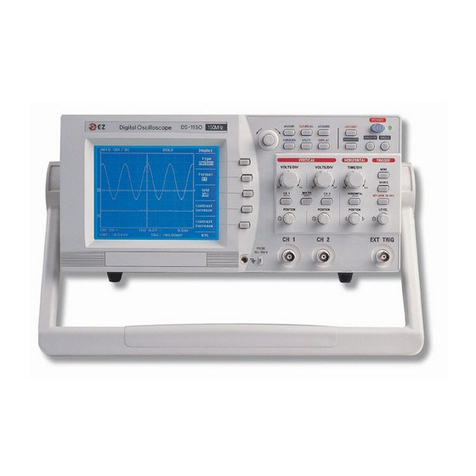
EZ Digital OS-5060A User manual

Oscilloscope
Analog Oscilloscope
Operation Manual
Free Datasheet http://www.datasheet4u.com/

Oscilloscope
Analog Oscilloscope
Operation Manual
Free Datasheet http://www.datasheet4u.com/

Safety Summary
Safety Precautions
Please take a moment to review these safety precautions.
They are provided for your protection and to prevent damage to the oscilloscope.
This safety information applies to all operator and service personnel.
Caution and warning statements.
CAUTION : Isused toindicatecorrectoperating ormaintenance
procedures in order to prevent damage to or destruction of the
equipment or other property.
WARNING : Calls attention to a potential danger that requires correct
procedures orpractices in order to prevent personal injury.
Symbols
Caution(refer to accompanying documents) and Warning
Protective ground(earth) symbol
Free Datasheet http://www.datasheet4u.com/

Introduction
Thank you for purchasing a EZ product. Electronic measuring instruments
produced by EZ digital are high technology products made under strict quality
control. We guarantee their exceptional and utmost reliability. For proper use of
the product please read this manual carefully.
Note
1. To maintain the precision and reliability of the product use it in the
standard setting(temperature 10℃~35℃and humidity 45%~85%)
2. After turning on-power, please allow a 15minute preheating period before using.
3. This equipment should be used with a triple line power cord for safety.
4. For quality improvement the exterior design and specifications of the
product can be changed without prior notice.
5. If you have further questions concerning use, please contact the EZ
Digital service center or sales outlet.
Free Datasheet http://www.datasheet4u.com/

Warranty
Warranty service covers a period of one year from the date of original purchase.
In case of technical failure within a year, repair service will be provided by our
service center or sales outlet free of charge.
We charge for repairs after the one-year warranty period expires.
When the failure is a result of user’s neglect, natural disaster or accident, we
charge for repairs regardless of the warranty period.
For more professional repair service, be sure to contact our service center or
sales outlet.
Free Datasheet http://www.datasheet4u.com/

CONTENTS
1. INTRODUCTION
1-1. SPECIFICATION ------------------------------------------- 7
1-2. PRECAUTIONS -------------------------------------------- 10
2. OPERATING INSTRUCTIONS
2-1. FUNCTION of CONTROLS -------------------------------- 13
2-1-1. Display and Power Blocks -------------------------- 13
2-1-2. Vertical Amplifier Block ------------------------------ 14
2-1-3. Sweep and Trigger Blocks -------------------------- 16
2-1-4. Miscellaneous Features ------------------------------ 18
2-2. BASIC OPERATING PROCEDURES
2-2-1. Preliminary Control Settings and Adjustments -- 19
2-2-2. Signal Connections ------------------------------------ 22
2-2-3. Signal Trace Operation ------------------------------- 23
2-2-4. Dual Trace Operation --------------------------------- 25
2-2-5. Trigger Options ----------------------------------------- 27
2-2-6. Additive and Differential Operation ------------------ 30
2-2-7. X-Y Operation --------------------------------------------- 31
2-2-8. Delayed-time base Operation ------------------------- 32
2-3. MEASUREMENT APPLICATIONS
2-3-1. Amplitude Measurements ---------------------------- 35
2-3-2. Time Interval Measurements ------------------------ 39
2-3-3. Frequency Measurement ----------------------------- 41
2-3-4. Phase Difference Measurement -------------------- 43
2-3-5. Rise Time Measurement ------------------------------ 47
Free Datasheet http://www.datasheet4u.com/

3. USER MAINTENANCE GUIDE ---------------------- 49
3-1. CLEANING ----------------------------------------------------- 49
3-2. CALIBRATION INTERVAL --------------------------------- 49
4. DIAGRAMS ------------------------------------------------------ 50
4-1. EXTERNAL VIEWS ------------------------------------------ 50
4-2. BLOCK DIAGRAMS ------------------------------------------ 51
Free Datasheet http://www.datasheet4u.com/

1. INTRODUCTION
1-1. SPECIFICATIONS
SPEC MODEL OS – 5060 A
6-inch rectangular screen with internal graticule ; 8X10 Div
(1div = 1Cm), making for measurement of rise time.
2mm subdivisions along the central axis.
+10Kv approx. (ref.cathode)
P31 (standard)
Possible(with autofocus correction circuit)
provided
variable
* CRT
1) Configuration
2) Accelerationg potential
3) Phosphor
4) Focussing
5) Trace rotation
6) Scale illumination
7) Intensity control provided
Positive going signal decreases intensity +5Vp-p or more
signal cases noticeable modulation at normal intensity setting
DC-3.5MHz (-3dB)
DC
20k – 30k ohms
* Z-Axis input
(Intensity Modulation)
1) Input signal
2) Band-width
3) Coupling
4) Input impedance
5) Maximum input voltage 30V(DC+peak AC)
(X1) DC to 60MHz normal
(X5) DC to 20MHz magnified
(X1) 10Mz to 60MHz normal
(X5) 10Mz to 20MHz magnified
CH1, CH2, ADD, DUAL(CHOP: Time/div switch 0.2s~5ms,
ALT:Time/divswitch2ms~0.1㎲)
5mV/div to 5V/div in 10calibrated steps of a 1-2-5 sequence.
Continuously variable between steps at least 1 : 2.5
X5 MAG : 1 mV /div to 1V/div in 10calibrated steps.
Normal: ±3% magnified: ±5%
* Vertical Deflection(1)
1) Band-width(-3dB)
DC coupled
AC coupled
2) Modes
3) Deflection Factor
4) Accuracy
5) Input impedance Approx. 1M-ohm in parallel with 25pF
6) Maximum input voltage Direct : 250(DC+peak AC), with probe :
refer to probe specification
7) Input coupling DC – GND – AC
7
Free Datasheet http://www.datasheet4u.com/

SPEC MODEL OS – 5060 A
5.8ns or less (23ns of less : X5 MAG)
20mV /div into 50 ohms : DC to 10MHz(-3dB)
CH2 only
delay cable supplied
A, A int B,B,B TRIGD, X-Y
0.1㎲/div to 0.2s/div in 20 calibrated steps 1-2-5 sequence
uncalibrated continuous control between steps at least : 2.5
Variable with the holdoff control
0.1㎲/div to 10㎲/div in 7 calibrated steps 1-2-5 sequence
1 div or less 10 div or more
Better than 1 : 20000
10time(maximum sweep rate : 20ns/div)
8) Rise time
9) CH1 out
* Vertical Deflection(2)
10) Polarity invertion
11) Signal delay
* Horizontal Deflection
1) Display modes
2) Time base A
Hold-off time
3) Time base B
Delayed sweep
Delay time jitter
4) Sweep magnification
5) Accuracy ±3%, ±5%(0˚to 50˚), additional error for magnifier ±2%
AUTO, NORM, TV-V, TV-H
CH1, CH2, LINE, EXT
AC
+ or -
20Hz-2MHz 2MHz-60MHz
INT 0.5 div 1.5 div
EXT 0.15 Vp-p 0.3 Vp-p
at least 1 div or 1.0Vp-p
1M-ohm in parallel with approx 30pF
* Trigger System
1) Modes
2) Source
3) Coupling
4) Slope
5) Sensitivity and
Frequency
AUTO, NORM
TV-V, TV-H
6) External trigger
Input impedance
Max input voltage 250V(DC + peak AC)
8
Free Datasheet http://www.datasheet4u.com/

<Caution> Sources like small hand-held radio transceivers, fixed station radio and television transmitters, vehicle
radio transmitters and cellular phones penetrate electromagnetic radiation that may induce voltages in the leads of a
test probe in such cases the accuracy of the oscilloscope cannot be guaranteed due to physical reasons. Conducted and
radiated emission are only kept under the condition that 4 DIV scale is used.
9
SPEC MODEL OS – 5060 A
(same as CH1 except for the following)
Deflectionfactor : same as that of CH1
Accuracy : ±5%
Frequency response : DC to 500kHz(-3dB)
Same as CH2
* X-Y Operation
1) X-axis
2) Y-axis
3) X-Y phase difference 3˚or less(at DC to 50kHz)
* Calibrator(probe adj.) approx. 1KHz frequency 0.5V(±3%)squar wave duty ratio:50%
Fuse(250V)
Voltage range UL198G IEC127
100( 90 – 110V)/AC
120(108 – 132V)/AC 2A F2A
220(198 – 242V)/AC
230(207 – 250V)/AC 1A F1A
50/60Hz
* Power Supply
1) Voltage range
2) Frequency
3) Power consumption approx. 45W
6.0kg
* Physical Charac.
1) Weight
2) Dimension 320mm(W) X 140mm(H) X 430mm(L)
+10˚C to +35˚C(+50˚F to +95˚F)
0˚C to +40˚C(+32˚F to 104˚F)
-20˚C to +70˚C(-4˚F to 158˚F)
45% to 85% RH
* Environmental Charac.
1) Temperature range
for rated operation
2) Max. ambient
operation temperature
3) Max. storage
temperature
4) Humidity range for
rated operation
5) Max. ambient
operating humidity
35% to 85% RH
* Safety IEC1010-1 overvoltage CAT Ⅱ, degree of pollution 2
* EMC Interference : EN55022 class B
Susceptability : EN50082-1, IEC801-2, 3, 4
* Accessories 1) Operation Manual : 1
2) Probes(Option) : 2
3)Fuse :1
4) AC Power Cord : 1
Free Datasheet http://www.datasheet4u.com/

1-2. PRECAUTIONS
1-2-1. Line Voltage Selection
The instrument must be operated with the correct Line Voltage Selector switch setting
and the correct line fuse for the line voltage selected to prevent damage. The instrument
operates from either a 90 to 132 volts or a 198 to 250 volt line voltage source. Before
line voltage is applied to the instrument, make sure the Line Voltage Selector switch is
set correctly.
To change the line voltage selection :
1. Make sure the instrument is disconnected from the power source.
2. Pull out the Line Voltage Selector switch on the rear panel. Select the arrow mark
position of the switch from Table 1-1. Slide the arrow mark to the desired position and
plug it in.
3. Pull out the Line Fuse Holder containing the fuse for overload protection. Replace the
fuse in the holder with the correct fuse from Table 1-1 and plug it in.
Table 1-1. Line Voltage Selection and Fuse Ratings
Fuse Rationgs(250V)
Line Voltage Arrow Mark Position UL198G IEC127
90 to 110 volts 100
108 to 132 volts 120 2A F2A
198 to 242 volts 220
207 to 250 volts 230 1A F1A
10
Free Datasheet http://www.datasheet4u.com/

1-2-2. Installation and handling precautions
When placing the OS-5060A in service at your workplace, observe the following
precautions for best instrument performance and longest service life.
1. Avoid placing this instrument in an extremely hot or cold place. Specifically, don’t leave
this instrument in a close car, exposed to sunlight in midsummer, or next to a space heater.
2. Don’t use this instrument immediately after bringing it in from the cold. Allow
time for it to warm to room temperature. Similarly, don’t move it from a
warm place to a very cold place, as condensation might impair its operation.
3. Do not expose the instrument to wet or dusty environments.
4. Do not place liquid-filled containers (such as coffee cups) on top of this
instrument. A spill could seriously damage the instrument.
5. Do not use this instrument where it is subject to severe vibration, or strong blows.
6. Do not place heavy objects on the case, or otherwise block the ventilation holes.
7. Do not use this oscilloscope in strong magnetic fields, such as near motors.
8. Do not insert wires, tools, etc. through the ventilation holes.
9. Do not leave a hot soldering iron near the instrument.
10. Do not place this scope face down on the ground, or damage to the knobs may result.
11. Do not use this instrument upright while BNC cables are attached to the
rear-panel connectors. This will damage the cable.
12. Do not apply voltages in excess of the maximum ratings to the input connectors or
probes.
13. This oscilloscope is to use UL listed double insulated probes only.
Free Datasheet http://www.datasheet4u.com/

12
Free Datasheet http://www.datasheet4u.com/

This section contains the information needed to operate the OS-5060A and utilize it in a
variety of basic and advanced measurement procedures. Included are the identification
and function of controls, connectors, and indicators, startup procedures, basic operating
routines, and selected measurement procedures.
2-1. FUNCION OF CONTROLS, CONNECTORS, AND INDICATORS
Before turning this instrument on, familiarize yourself with the controls, connectors,
indicators, and other features described in this section, The following descriptions are
keyed to the items called out in Figures 2-1.
2-1-1 Display and Power Blocks
Item Function
(1) POWER switch : Push in to turn instrument power on and off.
(2) POWER lamp : Lights when power is on.
(3) INTEN control : Adjusts the brightness of the CRT display.
Clockwise rotation increases brightness.
(4) FOCUS control : To obtain maximum trace sharpness.
(5) ROTATION control : Allows screwdriver adjustment of trace
alignment with regard to the horizontal
graticule lines of the CRT.
(6) ILLUM control : To adjust graticule illumination for
photographing the CRT display.
(7) VOLTAGE SELECTOR : Permits changing the operating voltage range.
(8) POWER CONNECTOR : Permits removal or replacement of the AC
power cord.
13
Free Datasheet http://www.datasheet4u.com/

2-1-2 Vertical Amplifier Block
(9) CH1 or X IN connector : For applying an input signal to vertical-
amplifier channel 1, or to the x-axis
(horizontal) amplifier during X-Y operation.
<CAUTION> To avoid damage to the oscilloscope, do not apply more than
250V(DC+Peck AC) between “CH1” terminal and ground.
(10) CH2 or Y IN connector : For applying an input signal to vertical-
amplifier channel 2, or to the Y-axis
(vertical) amplifier during X-Y operation.
<CAUTION> To avoid damage to the oscilloscope, do not apply more than
250V(DC+Peck AC) between “CH2” terminal and ground.
(11) CH1 AC/GND/DC switch To select the method of coupling the input
signal to the CH1 vertical amplifier.
ACposition inserts a capacitor between the
Input connector and amplifier to block any
DC component in the input signal.
GND position connects the amplifier to ground
Instead of the input connector, so a ground
Reference can be established.
DC position connects the amplifier directly
To its input connector, thus passing all
Signal components on to the amplifier
(12) CH2 AC/GND/DC switch To select the method of coupling the input
signal to the CH2 vertical amplifier.
(13) CH1 VOLTS/DIV switch To select the calibrated deflection factor of
the input signal fed to the CH1 vertical amplifier
(14) CH2 VOLTS/DIV switch To select the calibrated deflection factor of
the input signal fed to the CH2 vertical amplifier.
(15) (16) VARIABLE controls Provide continuously variable adjustment of
14
Free Datasheet http://www.datasheet4u.com/

deflection factor between steps of the VOLTS
/DIV switches. VOLTS/DIV calibrations are
accurate only when the VARIABLE controls are
click-stopped in their fully clockwise position.
(15) (16) VARIABLE control To increase the vertical amplifier sensitivity
(on VARIABLE) by 5 times. The effective scale factor of the
most sensitive position of the VOLTS/DIV switch
thereby becomes 1mV/div.
(17) CH1 POSITION control For vertically positioning the CH1 trace on
the CRT screen, Clockwise rotation moves the
trace up, counterclockwise rotation moves the
trace down.
(18) CH2 POSITION For vertically positioning the CH2 trace on the CRT
screen. Clockwise rotation moves the trace up,
counterclockwise rotation moves the trace downward.
(18) PULL CH2 INV switch When pulled, the polarity of the CH2 signal
(on CH2 POSITION control) is inverted.
(19) V MODE switch When pulled, the polarity of the CH2 signal
is inverted.
To select the vertical-amplifier display
mode.
CH1position displays only the channel 1
Input signal on the CRT screen.
CH2position displays only the channel 2
Input signal on the CRT screen.
DUAL position displays the CH1 and
CH2 input signal on the CRT screen
simultaneously.
CHOP mode : TIME/DIV 0.1s~5ms
ALT mode : TIME/DIV 2ms~0.1㎲
ADD position displays the algebraic sum of CH1
&CH2 signals.
(20) CH1 OUTPUT connector Provides amplified output of the channel 1
signal suitable for driving a frequency
counter or other instrument.
Free Datasheet http://www.datasheet4u.com/

2-13 Sweep and Trigger Blocks
(21) HORIZ DISPLAY switches To select the sweep mode.
Apushbutton sweeps the CRT at the main (A)
Timebaserate when pressed.
AINTpushbutton sweeps the CRT at the main
(A) timebase rate when pressed, and the B
timebase intensifies a section of the trace(s) The
location of the intensified section is determined
by the DELAY TIME POS control.
B pushbutton sweeps the CRT at the rate selected
By the B TIME/DIV SWITCH, AFTER A DELAY
DETERMINED BY THE A TIME/DIV switch and the
DELAY TIME POS control.
X-Y push button provides X-Y operation.
B TRIG’D pushbutton sweeps the CRT at the
rate selected by the B TIME/DIB switch when
triggered by the first trigger pulse occurring after
the delay time determined by the A TIME/DIV
switch and the DELAY TIME POS control.
(22) A TIME/DIV switch To select either the calibrated sweep rate of the
main (A) timebase, the delay-time range for
delayed-sweep operation.
(23) B TIME/DIV switch To select the calibrated sweep rate of the delayed
(B) timebase.
(24) DELAY TIME POS
control
To determine the exact starting point within the
A timebase delay range at which the B timebase
Will begin sweeping
(25) A VARIABLE control Provides continuously variable adjustment of
sweep rate between steps of the A TIME/DIV
switch. TIME/DIV calibrations are accurate only
when the A VARIABLE control is click-stopped
fully clockwise.
(25) PULL X 10 MAG switch To expand the horizontal deflection by 10 times,
(on A VARIABLE control) thus increasing horizontal sensitivity by 10 times
for X-Y operation, and increasing the effective
Free Datasheet http://www.datasheet4u.com/

sweep speed by 10 times.
(26) Horizontal POSITION To adjust the horizontal position of the traces
control displayed on the CRT. Clockwise rotation moves
the traces to the right, counterclockwise rotation
moves the traces to the left.
(27) Trigger MODE switch To select the sweep triggering mode.
AUTO position selects free-running sweep where
a baseline is displayed in the absense of a
signal. This condition automatically reverts
to triggered sweep when a trigger signal of 25
Hz or higher is received and other trigger
controls and properly set.
NORMposition produces sweep only when a trigger
Signal is received and other controls are properly
Set. No trace is visible if any trigger requirement
Is missing. This mode must be used when the signal
Frequency is 25 Hz or lower.
TV-Vposition is used for observing a composite
Video signal at the frame rate.
TV-Hposition is used for observing a composite
Video signal at the frame rate.
(28) Trigger SOURCE switch To conveniently select the trigger source.
CH1position selects the channel 1 signal as
The trigger source.
CH2position selects the channel 2 signal as
The trigger source.
LINEposition selects a trigger derived from the
AC power line. This permits the scope to sta-
Bilize display line-related components of a signal
Even if they are very small compared to other
Components of the signal/
EXT position selects the signal applied to the
EXT TRIG IN connector.
(29) HOLD OFF control Allows triggering on certain complex signals by
changing the holdoff (dead) time of the main
Free Datasheet http://www.datasheet4u.com/

(A) sweep. This avoids triggering on intermediate
trigger points within the repetition cycle of the
desired display. The holdoff time increases
with clockwise rotation.
NORM is a position at full counterclockwise
Rotation that is used for ordinary signals.
(30) Trigger LEVEL control To select the trigger-signal amplitude at which
triggering occurs. When rotated clockwise, the
trigger point moves toward the positive peak of
the trigger signal. When this control is rotated
counterclockwise, the trigger point moves toward
the negative peak of the trigger signal.
(30) Trigger SLOPE switch To select the positive or negative slope of the
(on LEVEL control) trigger signal for initiating sweep. Pushed in, the
switch selects the positive (+) slope. When
pulled, this switch selects the negative (-) slope.
(31) EXT TRIG IN connector For applying external trigger signal to the trigger
circuits.
<CAUTION> To avoid damage to the oscilloscope, do not apply more than
250V(DC+Peak AC) between “EXT Trig In” terminal and
ground.
2-1-4. Miscellaneous Features
(32) EXT BLANKING INPUT For applying signal to intensity modulate the
connector CRT. Trace brightness is reduced with a posi-
tive signal, and increased with a negative signal.
(33) CAL connector Provides a fast-rise square wave of precise
amplitude for probe adjustment and vertical
amplifier calibration.
(34) Ground connector Provides an attachment point for a separate
ground lead.
Free Datasheet http://www.datasheet4u.com/

2-2 BASIC OPERATING PROCEDURES
The following paragraphs in this section describe how to operate the OS-5060A,
Beginning with the most elementary operating modes, and progressing to the less
frequently-used and/or complex modes.
2-2-1 Preliminary Control Settings and Adjustments
Before placing the instrument in use, set up and check the instruments as follows ;
1. Set the following controls as indicated
POWER switch (1) OFF(released)
INTEN control (3) Fully CCW
FOCUS control (4) Mid rotation
AC/GND/DC switched (11) (12) AC
VOLTS/DIV switches (13) (14) 20 mV
Vertical POSITION controls (17) (18) Mid rotation and pushed in
VARIABLE controls (15) (16) Fully CW and pushed in
V MODE switch (19) CH1
HORIZ DISPLAY switches (21) A
A TIME/DIV switch (22) 0.5ms
A VARIABLE control (25) Fully CW and pushed in
Horizontal POSITION control (26) Mid rotation
Trigger MODE switch (27) AUTO
Trigger SOURCE switch (28) CH1
Trigger LEVEL control (30) Mid rotation
HOLDOFF control (29) NORM (Fully CCW)
2. Connect the AC Power Cord to the Power Connector (8), then plug the cord
into a convenient AC outlet.
3. Press in the POWER switch (1). The POWER lamp (2) should light immediately.
About 30 seconds later, rotate the INTEN control clockwise until the trace
Appears on the CRT screen. Adjust brightness to your liking.
CAUTION :A burn-resistant material is used
in the CRT. However if the CRT is left with
an extremely bright dot or trace for a very
long time, the screen may be damaged. There-
fore, if a measurement requires high brightness,
be certain to turn down the INTEN control
Free Datasheet http://www.datasheet4u.com/
Table of contents
Other EZ Digital Test Equipment manuals