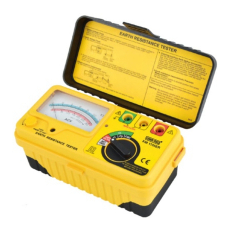
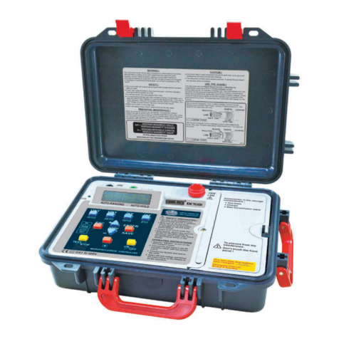
Kusam-meco KM 4234 ER User manual

G-17, Bharat Industrial Estate, T. J. Road, Sewree (W), Mumbai - 400 015. INDIA.
Sales Direct.: 022 -24156638, Tel. : 022-24124540, 24181649, Fax : 24149659
An ISO 9001:2008 Company
®
All Specifications are subject to change without prior notice
Navin.com/D.drive/sandeep gupta/New catlog Dec 2011/KM-4234ER.cdr
An ISO 9001:2008 Company
®
DIGITAL EARTH RESISTANCE TESTER4 WIRE
Model KM 4234ER
FEATURES :
=Auto-ranging microprocessor controlled.
=Earth testing range 2W, 20W, 200W, 2kW.
=Earth voltage measuring : 0-300V AC.
=Automatic C spike check.
=Automatic P spike check. =2-wire test, 3-wire test, 4-wire test.
=LCM display.
=Auto power OFF.
=Data Hold.
=Robust, Compact and easy to carry.
GENERAL SPECIFICATIONS :
íMeasuring Ranges : Earth Resistance : 0-2W, 0-20W, 0-200W, 0-2kW
Earth Voltage : 0-300V AC
íEarth Resistance Resolution : 0-2W: 0.01W0-20W: 0.1W
0-200W: 1W0-2kW: 10W
íAccuracy : Earth Resistance : ± 2%rdg ± 3dgt
Earth Voltage : ± 2%rdg ± 3dgt
íTemperature & Humidity : Operating : 0°C ~ 50°C £80% R.H.
Storage : -10°C ~ 60°C £80% R.H.
íPollution Degree : 2
íAltitude : up to 2000m.
íPower Supply : 1.5V (AA) X 8
íDimensions : 250 (L) x 190 (W) x 110 (D)mm
íWeight : Approx. 1430g (battery included)
EES S H
C2
P2
P1
C1
MAX.
AC 300V
Earth electrode
(rod) under test Test spike
EARTH VOLTAGE MEASUREMENT
E ES S H
C2
P2
P1
C1
MAX.
AC 300V
Earth electrode
(rod) under test
Current
spike
Potential
spike
FOUR-TERMINAL EARTH RESISTANCE MEASUREMENT
EES S H
C2
P2
P1
C1
MAX.
AC 300V
Earth electrode
(rod) under test
Current
spike
Potential
spike
THREE-TERMINAL EARTH RESISTANCE MEASUREMENT
E ES S H
C2
P2
P1
C1
MAX.
AC 300V
Earth electrode
(rod) under test
!
Potential
spike
TWO-TERMINAL EARTH RESISTANCE MEASUREMENT
SAFETY :
LVD : EN 61010-1 : 2001; EMC : EN 61326-1:2006 Class B
CISPR 11 : 2003/A1:2004/A2:2006 Group 1 Class B; EN 61326-1:2006, EN 61000-4-2:2009, EN 61000-4-4:2004,
EN 61000-4-6:2009, EN 61000-4-3:2006/A1:2008; EN61010-1 CAT IV 300V.
ACCESSORIES :
Test leads (red-15m, black-10m, yellow-10m, green-5m), 4 Auxillary earth spikes, User Manual, Carrying case,
Shoulder belt, Batteries & Fuse (0.1A 250V)
!
!
!

AN ISO 9001:2008 COMPANY
®®
4 Wires Earth
Resistance Tester
OPERATION MANUAL
17, Bharat Industrial Estate, T. J. Road, Sewree (W),
Mumbai-400015. INDIA
Sales Direct: (022)24156638 Tel.:(022) 2412 4540, 2418 1649
Website : www.kusamelectrical.com; www.kusam-meco.co.in
LIST OF PRODUCTS
* Digital Multimeter * Digital AC & AC/DC Clampmeter
* AC Clamp Adaptor * AC/DC Current Adaptor
* Thermo Anemometer * Thermo Hygrometer
* Distance Meter * Digital Lux Meter
* Network Cable Tester * Power Factor Regulator
* Earth Resistance Tester * Digital Panel Meters
* DC Power Supplies * High Voltage Detector
* Calibrators * Gas Analysers
* Frequency Counter * Function Generator
* Phasing Sticks * Battery Tester
* Waterproof Pen Testers * Solar Power Meter
* EMF Detector
* Wood, Paper & Grain Moisture Meter
* Transistorised Electronic Analog & Digital Insulation
Resistance Testers(upto 10 KV)
* Digital Sound Level Meter & Sound Level Calibrator
* Digital contact & Non-contact Type Tachometer
* Digital Non-contact (infrared) Thermometer
* Maximum Demand Controller/Digital Power Meter
* Digital Hand Held Temperature Indicators
®®
Model No
KM 4234 ER

01
¨Outside and
service entrance
¨Service drop from
pole to building
¨Overhead line to
detached building
¨Feeders and short
branch circuits
¨Distribution panel
devices
¨Outlets and
long branch circuits
¨Electronic
Equipment
CAT IV - Is for measurements performed at the source of the low-voltage
installation.
CAT III - Is for measurement performed in the building installation.
CAT II - Is for measurement performed on circuits directly connected to the
low - voltage installation.
CAT I - Is for measurement performed on circuits not directly connected to
mains.
1. INTRODUCTION
CAT III
CAT IV CAT II CAT I
Power
Line
SERVICE
ENTRANCE
INDEX
1) INTRODUCTION......................................................
2) SAFETY NOTES.......................................................
3) FEATURES................................................................
4) SPECIFICATIONS.....................................................
5) INSTRUMENT LAYOUT.............................................
6) MEASURING METHODS..........................................
7) FUSES REPLACEMENT...........................................
8) MAINTENANCE .......................................................
PAGES
1
2
3
4
5
6-8
8
9
This Meter has been designed and tested according to the IEC
Publication 348, Safety requirements for Electronic Measuring
Apparatus, EN 61010-1, EN-61326-1, EN 61557-1, EN-61557-5
and other safety standards. Follow all warnings to ensure safe

03
3) FEATURES
=Microprocessor controlled with advanced safety features
=LCM display
=Auto - Ranging
=Earth resistance testing at C-2W/ 0-20W/0-200W/ 0 - 2kW
=Earth voltage measuring : 0 ~300Vac
=Automatic C spike check.
=Automatic P spike check.
=2- Wire test
=3- Wire test
=4- Wire test
=Auto power off
=Data hold
=Robust, Compact and easy to carry.
=Safety standard : EN 61010-1 CAT IV 300V
EN 61326-1
EN 61557-1
EN 61557-5
02
2)SAFETY NOTES
=Read the following safety information carefully before attempting
to operate or service the detector.
=Use the meter only as specified in this manual, otherwise, the
protection provided by the meter may be impaired.
=Rated environment conditions :
1) Indoor & out door use
2) Installation Category IV 300V.
3) Pollution Degree 2.
4) Altitude up to 2000m
5) Relative Humidity 80% max.
0
6) Ambient temperature 0 ~ 40 C
=Observe the International Electrical Symbols listed below:
Detector is protected throughout by double
insulation or reinforced insulation.
Warning ! Risk of electric shock.
Caution ! Refer to this manual before using the detector.
Earth (ground) terminal.
Equipment complies with current EU directives.

04
4) SPECIFICATION
Earth Resistance
Measuring Ranges 0-2W, 0-20W, 0-200W, 0-2kW
Earth Voltage
0-300 V AC
Accuracy Earth Resistance
±2% rdg ±3dgt
Earth Voltage
±2% rdg ±3dgt
0-2W: 0.01W
Earth Resistance 0-20W: 0.1W
Resolution 0-200W: 1W
0-2kW: 0.01kW
0 0
Temperature & Operating : 0 C ~ 50 C £80% R.H.
0 0
Humidityu Storage : -10 C~60 C £80% R.H.
Power source 1.5V (AA) x 8
Dimension 250 (L) x 190 (W) x 110 (D)mm
Weight Approx. 1430g (battery included)
Test Leads (red- 15m, black -10m,
green-5m) Auxiliary earth spikes
Instruction manual carrying case
batteries
Accessories Fuse (0.1A/250 V 5 X 20mm)
!
E
C1
ES
P1
MAX
AC 300V
S
P2
H
C2
1 2 3 4
TEST / STOP
ON/OFFACV4P3P2PACV
8 9 10 11 12
13
EARTH RESISTANCE TESTER
AUTO OFF
AUTO RANGING
MICROPROCESSOR CONTROLLED
RL
RP
5
6
7
1) C1 terminal
(Black test lead connection)
2) P1 terminal
(Green test lead connection)
3) P2 terminal
(Yellow test lead connection0
4) C2 terminal
(Red test lead connection)
5) LCM display
6) Rc LED
7) Rp LED
8) 2 Wires type button
9) 3 Wires type button
10) 4 Wires type button
11) ACV button
12) Power button
13) TEST/STOP button
5) INSTRUMENT LAYOUT
05

06
a. Test leads connection.
Earth Electrode
(rod) under test
Test Spika
!
E
C1
ES
P1
MAX
AC 300V
S
P2
H
C2
Earth Voltage measurement
6) MEASURING METHODS
1) Battery Voltage Check
a. Before testing, press the "ON/OFF" button, when the
"Battery : Low" appears or the display, replace with new
batteries.
b. Prior to measuring, If "Battery : Low" appears on the display,
replace with new batteries
2) Earth Voltage Check
a. Test leads connection.
b. Press the "ON/OFF" button, "ACV" button and
"TEST/STOP" button, earth voltage will be displayed
on the LCM. When the earth voltage is more than 10V
It may result in errors in earth resistance measurement.
Make sure that the indicated value is less than 10V
3) Earth resistance measurement
The measured results may be influenced by induction
if measurement are made with the test leads twisted
or connected each other. When connecting the Probes,
they should be separated.
07
Earth electrode (rod) under test potential spike
b. Select testing type : "2P", "3P" or "4P" and press button
c. Press "TEST/STOP" button to test and take a reading
=When you make the "4P measurement", LCD Shows
"Vp Error", Short Circuit C1 (Black) and P1 (green).
=Stick the three Auxiliary Earth spikes into the ground
deeply. The distance must be 5 ~ 10m between the
Auxiliary Earth Spikes.
Earth Electrode
(rod) under test
Potential
Spike
Current
Spike
!
E
C1
ES
P1
MAX
AC 300V
S
P2
H
C2
!
E
C1
ES
P1
MAX
AC 300V
S
P2
H
C2
Earth Electrode
(rod) under test
Potential
Spike
Current
Spike
!
E
C1
ES
P1
MAX
AC 300V
S
P2
H
C2
Four - terminal earth resistance measurement
Three - terminal earth resistance measurement
Two - terminal earth resistance measurement

08
=Cleaning And Storage :
8) MAINTENANCE
WARNING
Do not mix new and old batteries together.
=Battery Replacement :- When the Battery "Low" appears on
the display, replace the batteries as follows :
1) Disconnect the test leads from the instrument and remove the
battery cover and the batteries.
2) The tester's battery is situated under the tester.
3) Replace with eight 1.5V AA light batteries, taking care to
observe correct polarity.
4) Reinstall battery holder and the battery cover.
WARNING
To avoid electrical shock or damage to the
meter, do not get water inside the case..
Periodically wipe the case with a damp cloth and detergent :
do not use abrasives or solvents.
09
Notes :
Check the following prior to proceeding with measurement:
1) Checking if Auxiliary Earth Spikes connect correctly when
the "RC" LED lit.
2) Indication for "Rc" & Rp"
Rc : When the "Rc" LED lit, this means there is no test current
output.
Rp : When the "Rp" LED is lit, the "R" value on the LCD
will displayed "> 2kW", this means testing Earth resistance
value is over 2kW.
7) FUSE REPLACEMENT
WARNING
Only replace with the same fuse specification
1) Disconnect the test leads from the instrument.
2) The fuse is located under the battery holder.
3) Open the battery cover. then remove and replace the fuse
with the new one.
4) Fix the cover after replacing a fuse and screw up the
cover. Fuse Spec. 0.1A / 250V, 5 x 20mm
Fuse (0.1A / 250V)

WARRANTY
Each “KUSAM-MECO” product is warranted to be free from defects in
material and workmanship under normal use & service. The warranty
period is one year (12 months) and begins from the date of despatch
of goods. In case any defect occurs in functioning of the instrument,
under proper use, within the warranty period, the same will be
rectified by us free of charges, provided the to and fro freight charges
are borne by you.
This warranty extends only to the original buyer or end-user customer
of a “KUSAM-MECO” authorized dealer.
This warranty does not apply for damaged Ic’s, burnt PCB’s, fuses,
disposable batteries, carrying case, test leads, or to any product
which in “KUSAM-MECO’s” opinion, has been misused, altered,
neglected, contaminated or damaged by accident or abnormal
conditions of operation or handling.
“KUSAM-MECO” authorized dealer shall extend this warranty on
new and unused products to end-user customers only but have no
authority to extend a greater or different warranty on behalf of
“KUSAM-MECO”.
“KUSAM-MECO’s” warranty obligation is limited, at option, free of
charge repair, or replacement of a defective product which is returned
to a “KUSAM-MECO” authorized service center within the warranty
period.
THIS WARRANTY IS BUYER’S SOLE AND EXCLUSIVE REMEDY
AND IS IN LIEU OF ALL OTHER WARRANTIES, EXPRESS OR
IMPLIED, INCLUDING BUT NOT LIMITED TO ANY IMPLIED
WARRANTY OF MERCHANTABILITY OR FITNESS FOR A
PARTICULAR PURPOSE. “KUSAM-MECO” SHALL NOT BE
LIABLE FOR ANY SPECIAL, INDIRECT, INCIDENTAL OR
CONSEQUENTIAL DAMAGES OR LOSSES, INCLUDING LOSS
OF DATA, ARISING FROMANY CAUSE WHATSOEVER.
All transaction are subject to Mumbai Jurisdiction.
11
The instrument has been calibrated by using equipment
which has already been calibrated to standards traceable
to national standards.
MODEL NO. ____________
SERIAL NO. ___________
This Test Certificate warrantees that the product has been
inspected and tested in accordance with the published
specifications.
ISO 9001
REGISTERED
QC
PASS
KUSAM-MECO
DATE: ___________
KM 4234ER
MUMBAI
TEST CERTIFICATE
EARTH RESISTANCE TESTER
10
Table of contents
Other Kusam-meco Test Equipment manuals

Kusam-meco
Kusam-meco KM 2803IN User manual

Kusam-meco
Kusam-meco KM-CAL-905 User manual

Kusam-meco
Kusam-meco KM 66 User manual

Kusam-meco
Kusam-meco KM-1520 User manual

Kusam-meco
Kusam-meco KM 36 User manual

Kusam-meco
Kusam-meco KM-CAL-801 User manual

Kusam-meco
Kusam-meco KM -CAL 803 User manual

Kusam-meco
Kusam-meco KM 3600 User manual

Kusam-meco
Kusam-meco KM-CAL-907 User manual

Kusam-meco
Kusam-meco KM-CAL-805 Installation manual