Detectortesters Testifire 1001 User manual

detectortesters
testing technology from No Climb
M U T I - S T I M U L U S D E T E C T O R T E S T E R
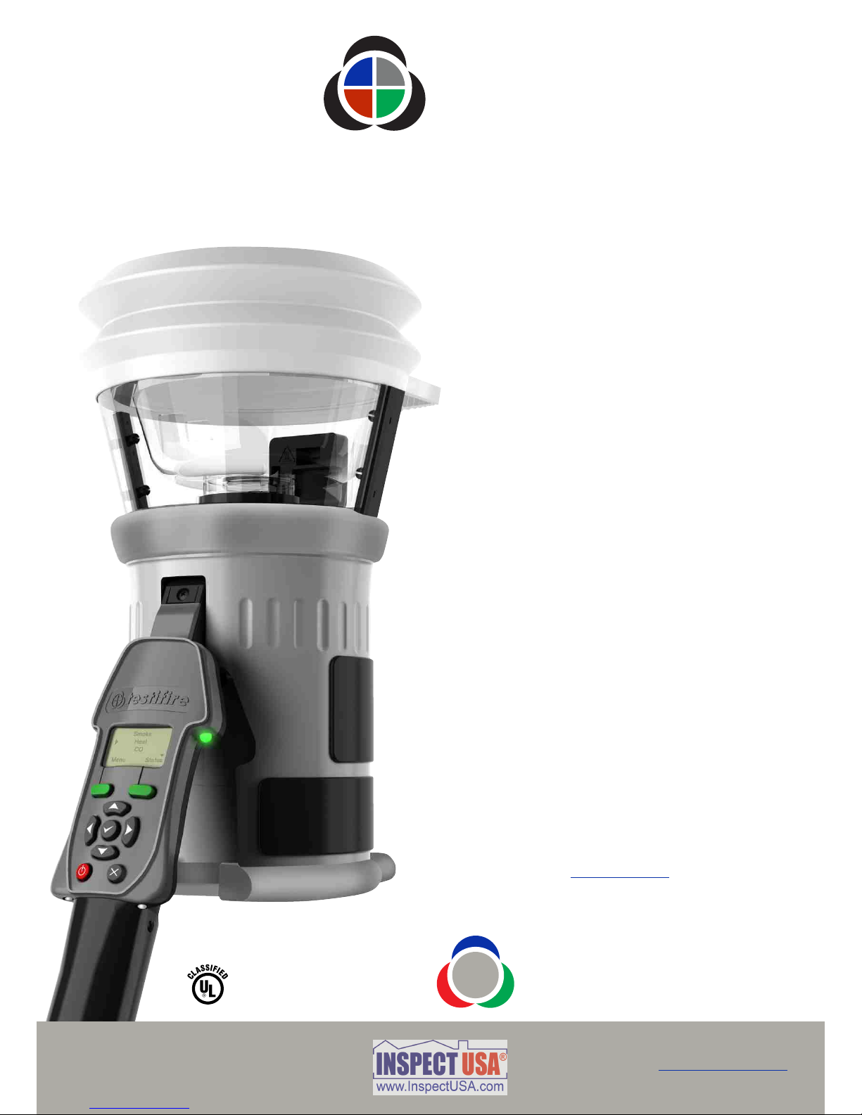
testifire®
M U L T I - S T I M U L U S D E T E C T O R T E S T E R
User Manual
www.testifire.com
M U T I - S T I M U L U S D E T E C T O R T E S T E R
testifire®
M U L T I - S T I M U L U S D E T E C T O R T E S T E R
User Manual
This manual provides information for the correct
use of the testifire® 1000 and 2000 series of
detector testers including:
®
Testifire 1000 Head Unit
®
Testifire 1001 Testing Kit
®
Testifire 6001 Testing Kit
®
Testifire 9001 Testing Kit
®
Testifire 2000 Head Unit
®
Testifire 2001 Testing Kit
®
Testifire 6201 Testing Kit
®
Testifire 9201 Testing Kit
Replacement Capsules
TS3 Smoke Capsule
TC3 CO Capsule
Additional Items
TM
Solo 760 Battery Baton™
TM
Solo 726 Universal Fast Battery Charger
TM
Solo 100 Telescope Pole
TM
Solo 101 Extension Pole
TM
Solo 200 Universal Detector Removal Tool
TM
Solo 610 Protective Carrying / Storage Bag
®
Testifire 25 Infrared Remote Control
® ®
Testifire 100 RFID Bluetooth Module*
A complete Product Selector of the Testifire
components and kits is shown on page 36 of this
User Manual.
For any additional information or technical support,
please contact your local distributor, or visit the
Testifire web site at: www.testifire.com
* Future option
Testifire 2000 illustrated
detectortesters
testing technology from No Climb
i
www.testifire.com
SIGNALING
Multi-Detector Test
Apparatus as to Verification
of Detector Functional
Operation Only
77TL

Important Information
Read this User Manual completely before using your Testifire.
Save this User Manual - Save all safety and operational instructions for future reference.
Take note of the Warnings - Read carefully and follow all warning labels on the product and those
described in this User Manual.
Water and Moisture - This product is designed for indoor use only and should not be subject to, or used in,
a wet environment.
Servicing - To make sure that your Testifire unit continues to perform as intended, it will require a regular
service. A standard period for service is every 12 months. In extreme use, a service could be required
sooner. Testifire has a built-in service interval timer and it will warn you when a service is due or overdue.
(See section 7.5 for more information).
Testifire is a precision electronic instrument and care should be taken when handling and storing. Dropping on
to a hard surface could damage it. Please look after it, treat it with care and it will last for many years.
To protect the high-precision technology contained in Testifire, never leave Testifire in the places listed below,
whether if in use or in storage:
Places where temperatures and/or humidity are high or go through extreme changes. Direct sunlight, or
near other heat sources (stoves, radiators, etc.) Always observe the operating and storage environment
restrictions detailed in the Technical Specifications (see Section 9)
In sandy or dusty environments.
In places prone to strong vibration.
Near to sources of static or radio waves.
Wet or moist environments. Testifire is designed for indoor use only.
Stop using Testifire immediately if you notice any unusual odours; liquids or noise coming from it. Switch off
immediately and consult technical support (section 7.1).
If your Testifire unit becomes damaged do not use it. Switch off immediately and consult technical support
(section 7.1).
Testifire is not designed for use in hazardous areas (those containing explosive vapour or dust).
Use only approved accessories that are recommended by the manufacturer for your Testifire model.
The Battery Baton should be removed when Testifire is not in use. This will prevent the gradual discharge of
the battery and prevent possible accidental operation of the head unit.
Do not use your Testifire if it is not operating properly. Consult the Troubleshooting section (section 6.0) of
this manual and if required seek technical advice.
If the equipment is used in a manner not specified by the manufacturer, the protection provided by the
equipment may be impaired.
Use only approved accessories that are recommended by the manufacturer for your Testifire model. (see
Section 9.1)
M U L T I -S T I M U L U S D E T E C T O R T E S T E R
testifire®
ii
www.testifire.com
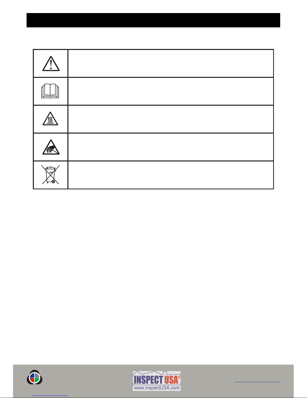
This symbol on the product indicates that there is a safety hazard.
This symbol on the product indicates that you should read and understand this User Manual
before using this product.
This symbol on the product warns you of hot surfaces or heat by convection.
This symbol on the product indicates that this part of the device is susceptible to static
damage.
The crossed-out refuse container symbol on this product or literature indicates that it should not be
disposed with other business waste at the end of its working life. To help ensure that valuable
resources are reused and recycled, and to prevent possible harm to the environment or human health
from uncontrolled waste disposal, please separate this from any other types of waste.
You must read the appropriate sections of the User Manual to understand the nature and
severity of all the potential hazards present and the action you must take.
Meanings of Symbols and Terms
The following symbols are used throughout this User Manual.
M U L T I - S T I M U L U S D E T E C T O R T E S T E R
testifire®
iii
www.testifire.com

Safety
WARNING
This product emits small amounts of carbon monoxide (CO) gas which is a harmful, odour-
less gas.
directly from the duct during a CO test or within 5 minutes of DO NOT INHALE
conducting a CO test.
Note: Under normal operating conditions, this emission will present no harm to the user.
For additional information please refer to the separate safety information provided.
CAUTION
This product contains hot surfaces and hot air is also emitted from the duct outlet.
the tip of the CO capsule when it has been removed if the unit has been DO NOT TOUCH
in operation within the previous 5 minutes. It will be very hot immediately after use and may
burn if touched.
insert fingers into the aperture from where the CO capsule has been removed. DO NOT
There are very hot surfaces which may burn if touched.
Avoid placing hands near the duct outlet during heat testing or within 5 minutes of
conducting heat testing.
Hot air is emitted from the duct and the top of the duct will get hot to the touch.
CAUTION
This product is intended to be used at height.
Exercise great care and always wear appropriate PPE (personal protective equipment) when
operating above head height in order to avoid the risk of injury.
. Keep proper footing and balance at all times. Proper footing and DO NOT OVER REACH
balance enables better control of the equipment in unexpected situations.
Pay particular attention to avoid contact with overhead items such as light fittings, overhead
power cables/busbars and any other objects that could be accidentally dislodged which
might cause danger to the operator or anyone else in the vicinity.
General Safety Information
M U L T I - S T I M U L U S D E T E C T O R T E S T E R
testifire®
iv
www.testifire.com

Table of Contents
M U L T I - S T I M U L U S D E T E C T O R T E S T E R
testifire®
v
www.testifire.com
Page No.
1. 4General Instructions
1.1 Warranty 4
1.2 Acknowledgement 4
1.3 Recycling 4
2. 5Introduction
3. 6Parts Identification
4. 7Preparation For Use
4.1 Charging the Battery 7
4.2 Using the Battery 8
4.3 Removal and Replacement of the Smoke and Carbon Monoxide (CO) Capsules 9
4.4 Turning the Unit On 10
4.5 Using the Menus 11
4.6 Adjusting the Head Unit Angle 11
4.7 Testing High Profile Detectors 12
5. 13Using Your Testifire
5.1 Sounder Option 14
5.2 Testing a Detector 14
5.3 Smoke Testing 15
5.4 Heat Testing 15
5.5 Carbon Monoxide (CO) Testing 17
5.6 Clearing the Detector 17
5.7 Capsule Fuel Level 1 8
5.8 Simultaneous Testing 19
5.9 Sequential Testing 19
5.10 Combined Simultaneous and Sequential Testing 2 0
5.11 Infrared Remote Control 20
5.12 RFID Auto Tests* 21
5.13 Indicating LED Reference Chart 22
6. 23Troubleshooting
6.1 Errors 23
6.2 System Reset 23
6.3 Error Messages and Indicating LED Reference Chart 24
7. 25Support
7.1 Technical Support 25
7.2 Future Updates 2 5
7.3 System Information 25
7.4 Maintenance 25
7.5 Servicing 26
7.6 Service Reminders 27
7.7 Testifire Flash Loader Software Instructions 28
8. 34Technical Specifications
8.1 Field Replaceable Parts 35
9. 36Product Selector
10. 37Agreement for Supply of Products and Associated Software
* Future option

1. General Instructions
1.1 Warranty
In addition to any other express warranty given in writing by the Company in relation to the Goods, the Company
warrants that the Goods supplied under these terms and conditions will be in accordance with the specification
(if any) contained in the Purchase Order, and will be free from defects in workmanship and material for a period of
18 months from the date of delivery to the Buyer or for a period of 12 months after the date of sale by the Buyer
to the final customer whichever period is the shorter.
1.2 Acknowledgement
Testifire®, Solo™and Battery Baton™are registered marks of No Climb Products Ltd. All other brand
names mentioned are trademarks or registered marks of their respective holders, and are hereby acknowledged.
©2010 No Climb Products Ltd.
All Rights Reserved.
1.3 Recycling
The packaging can be easily separated into the following materials:
Cardboard (outer box)
Cardboard (inner buffers, boxes)
Polyethylene (Capsule bags)
Plastic (Capsule caps)
Please dispose in line with local
environmental requirements.
WEEE (Waste Electrical & Electronic Equipment) Regulations 2006
Testifire and Testifire capsules are suitably marked to be recycled in accordance with your local environmental
requirements. Alternatively these items may be returned to the manufacturer via your reseller for disposal in
compliance with WEEE (Waste Electrical & Electronic Equipment) Regulations 2006.
RoHS Declaration
We declare that this product and its associated components are designed and manufactured to be fully compliant
with the requirements of the Directive 2002/95/EC Restrictions of use of certain Hazardous Substances in
Electrical and Electronic Equipment (The RoHS Directive).
EULA (End User Licence Agreement)
See Section 10.
page 4
www.testifire.com
M U L T I - S T I M U L U S D E T E C T O R T E S T E R
testifire®Back to Contents Page

2. Introduction
page 5
Testifire 1000 Series
Head Unit
Testifire 2000 Series
Head Unit
Thank you for purchasing Testifire Multi-Stimulus Detector Tester.
This manual is designed to assist you to get the best and most efficient use of the Testifire 1000 and 2000
model range, and provides all the information required to perform routine service and maintenance tasks
with ease.
Testifire includes an array of advanced and intelligent technologies that change traditional approaches to
functional testing in the field. Simply by being able to test all fire detectors with one unit is faster and
more productive. In addition the Testifire range brings health, safety, environmental and technological
benefits to field servicing of fire detectors as never seen before.
Testifire is a technologically advanced, fully field portable device for functional testing of fire detectors.
The unit is suitable for testing optical/photoelectric and ionisation smoke sensors, thermal sensors (fixed
temperature or rate-of-rise), and carbon monoxide (CO) fire sensors, be they conventional, addressable
or analogue addressable. Testifire is also the first functional tester that enables testing of multi-sensors or
multi-criteria detectors from a single test unit.
Testifire creates stimuli that the sensors are designed to detect. Depending on the model purchased,
Testifire can create smoke, heat and CO stimuli on demand from a single unit. Testifire creates stimuli
without using pressurised aerosol cans or hazardous media. Stimuli (Smoke, Heat, and CO) are generated
at the time of test using safe and patented processes fuelled by replaceable capsules.
Testifire can also execute programmed testing: Simultaneously (any combination of Smoke, Heat and CO),
Sequentially (e.g. Smoke, followed by Heat and then CO) or Combined Simultaneous and Sequentially
(e.g. Smoke and Heat together followed by CO). In addition it also incorporates a clearing mode that
enables the stimuli to be blown out of the detector immediately after a test, enabling more rapid resets at
the panel.
Testifire is also capable of reading from, and writing data to electronic RFID tags which may be installed
on detectors. This permits a level of automation in testing and logging of service and maintenance
activities. The facility for an optional RFID and Bluetooth®module is covered in detail in the RFID manual.
If you require additional information or assistance in the use of Testifire, please visit the support area of
our web site, or contact our technical support department as detailed on the Support page of this User
Manual.
M U L T I - S T I M U L U S D E T E C T O R T E S T E R
testifire®
www.testifire.com
Back to Contents Page
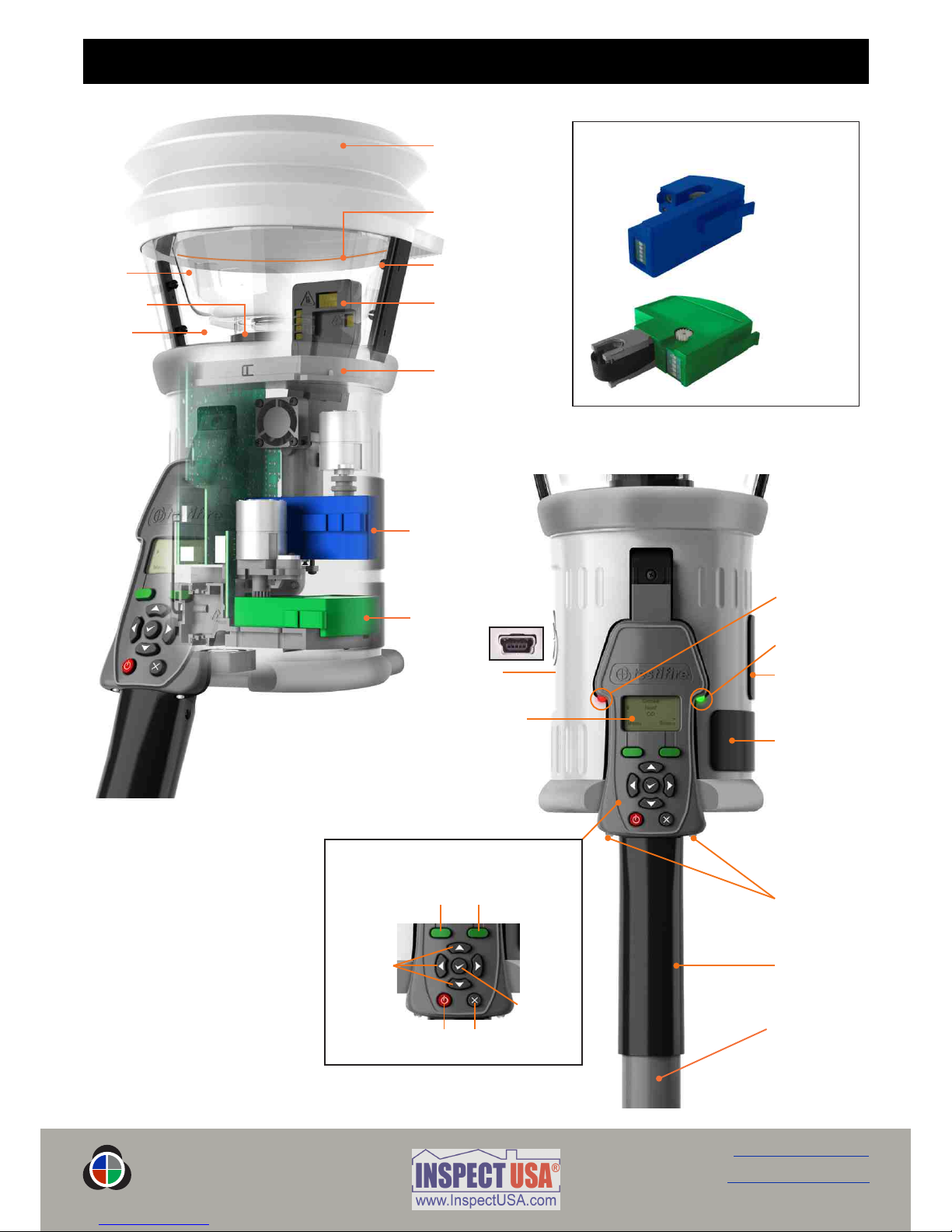
Main Duct for Heat,
Smoke and CO*
Testifire 100 RFID
Bluetooth®Module**
Bellows
RFID Antenna**
* Depending on model specification
** Future option
Platform
Testifire 2000 Illustrated
Inner
Clear
Cup Infrared Beam
3. Parts Identification
page 6
Battery Baton
Adjustable
Handle
User Interface
Display (LCD)
‘Status’ LED
‘Test Type’ LED
CO Capsule
Access Cover*
Smoke Capsule
Access Cover
USB Port
(on rear of unit)
Replacement Capsules
Smoke Capsule
TS3
CO Capsule
TC3*
Testifire Smoke
Capsule TS3
Testifire CO
Capsule TC3*
Status KeyMenu Key
Escape KeyON/OFF Key
Enter Key
Menu
Navigation
Keys
User Interface Keypad
Clear
Cup
M U L T I - S T I M U L U S D E T E C T O R T E S T E R
testifire®
Infrared Remote
Control
Receivers
www.testifire.com
Back to Contents Page
4. Preparation For Use
page 7
M U L T I - S T I M U L U S D E T E C T O R T E S T E R
testifire®
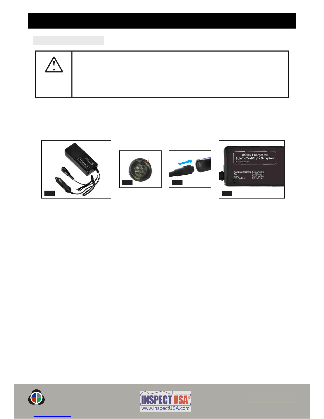
4.1 Charging the Battery
Solo NiMH Battery Batons are used to power Testifire and enable it to be fitted to Solo Access Poles.
The Solo760 Battery Baton must be charged before using Testifire. To obtain maximum duration of testing, it
should be fully charged for each use. The Solo726 charger should be used for charging Solo760 Battery Batons
(Fig. 1).
Connect charger to power outlet / vehicle accessory socket using power cable supplied / umbilical DC connecting
lead respectively. LED will not illuminate permanently (Fig. 4).
Connect the Battery Baton to the charger via the seven pin polarised connector and turn the locking
ring (Fig. 2 & 3).
LED will flash red/green initially, then illuminate red only to indicate fast charging. LED illuminates green only
when battery fully charged.
Charging times will depend on the discharge state of the Battery Baton. Charge times can be 75-90 minutes
when charging a fully discharged Battery Baton.
If LED flashes red, there is a battery fault.
NOTE: If Battery Baton is not to be used for some time (i.e. within the next day), it is advisable to unplug the
charger from the power supply.
As with all rechargeable batteries, after a few hundred cycles of normal use your Battery Baton will eventually
reach the end of its useable life and will hold less charge or not charge properly. At this point it is recommended
that replacement Battery Batons are purchased.
To ensure the longest possible battery life, discharge the Battery Baton fully before charging whenever possible
and avoid leaving the Battery Baton in a discharged state for long periods of time.
WARNING
Do not attempt to use or charge the battery if either the unit or the battery connection
point are damaged.
Never connect AC and DC power at the same time.
Fig. 1 Fig. 4
Fig. 2 Fig. 3
Locking Ring
www.testifire.com
Back to Contents Page

Fig. 5
Fig. 6
CAUTION
Ensure correct orientation when inserting Battery Baton into tool and do not use undue
force to insert.
Remove Battery Baton from Testifire when not in use.
page 8
M U L T I - S T I M U L U S D E T E C T O R T E S T E R
testifire®
www.testifire.com
Back to Contents Page
CAUTION
Store charger in a dry place (indoor use only when connected to AC mains). Danger of fire
and electric shock! Do not fast-charge a hot battery, allow the Battery Baton to cool down
naturally before starting a charge cycle. Allow the charger to cool down for at least 15
minutes after one fast charge. Stop charging if the Battery Baton becomes too hot during
charging (>55-60°C). Do not leave unattended whilst charging. Only clean with a dry cloth.
Do not attempt to open the charger. Repair permitted only by authorised dealer.
Battery Batons must be stored and charged in accordance with stated environmental
conditions.
Environment: Operating temperature:5 °C to 45°C / 40°F to 115°F
Storage temperature: - 10°C to 50°C / 15°F to 120°F
Humidity:0 -90% RH non-condensing
ATTENTION
This charger is designed for charging fast rechargeable NiMH Battery Batons (Solo 760) only. Do not connect
other types of batteries. Danger of explosion.
ENVIRONMENT
Battery Batons must be disposed of at a recognised recycling centre. Local authorities can provide advice on the
best method.
4.2 Using the Battery
To insert the Battery Baton into Testifire, hold the Testifire head unit by the
handle and depress the upper spring button on the Battery Baton. Align the
button with the location hole in the handle and push the Battery Baton into the
handle until the button springs up through the location hole (Fig. 5).
: Slight rotation of the Battery Baton may assist alignment when inserting.TIP
Insert the other end of the Battery Baton into the Solo access pole and depress
the lower spring button. Align it with the location hole and push the Battery
Baton further into the pole until the button springs up through the hole (Fig. 6).

page 9
Fig. 7
Spring Clips
Spring Clip
Protector
CAUTION
DO NOT TOUCH the black carbon tape of the CO capsule or surrounding area. The tip
and surrounding area may be hot after use.
CAUTION
insert fingers or other objects into the aperture from where the CO capsule has DO NOT
been removed. There are very hot surfaces which may burn or become damaged if touched.
CAUTION
This symbol on the product indicates that this part of the device is susceptible to static
damage.
the contacts on the PCB on the capsule. Static electricity may damage DO NOT TOUCH
them and contamination of the contacts must be avoided.
A
B
Fig. 8
C
B
M U L T I - S T I M U L U S D E T E C T O R T E S T E R
testifire®
B
B
www.testifire.com
Back to Contents Page
4.3 Removal and Replacement of the Smoke and Carbon Monoxide (CO) Capsules
Smoke and CO capsules are non-refillable. Only replace with genuine Testifire TS3 (Smoke) and TC3 (CO)
Capsules.
Note: Manufacturer’s warranty is conditional on the use of only genuine Testifire replacement parts which must
be replaced in accordance with the instructions supplied.
Please observe the local regulations regarding the disposal of packaging
materials, exhausted batteries and old electronic equipment.
Empty capsules may be returned to the manufacturer for environmentally-
friendly disposal via the reseller to comply with WEEE (Waste Electrical &
Electronic Equipment) Regulations 2006.
Only use gentle pressure when inserting the capsules.
Smoke Capsule Removal Instructions (Testifire 1000 and 2000 series)
Release the upper access cover (Fig. 7) on the body of the Testifire A
unit by opening it from the right hand side. Note: Testifire 1000
series units only have one access cover.
Squeeze the two clips (Fig. 7) on each side of the used capsule andB
gently pull the capsule out.
Smoke Capsule Replacement Instructions
Remove the capsule from its outer carton and anti-static bag.
Remove the spring clip protector cap (Fig. 8) from the new capsule.C
Holding the capsule by the spring clips (Fig. 8) with the label on theB
underside, carefully insert the new capsule into the capsule port. Push it
into position, ensuring that the clips spring out positively on both sides
of the capsule to engage correctly with the port.
Close the Smoke access cover (Fig. 7) securely.A
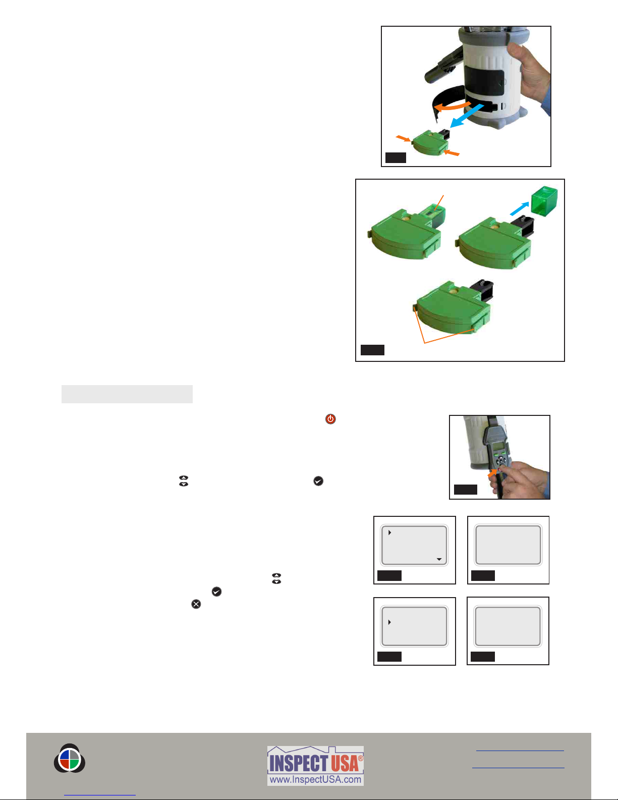
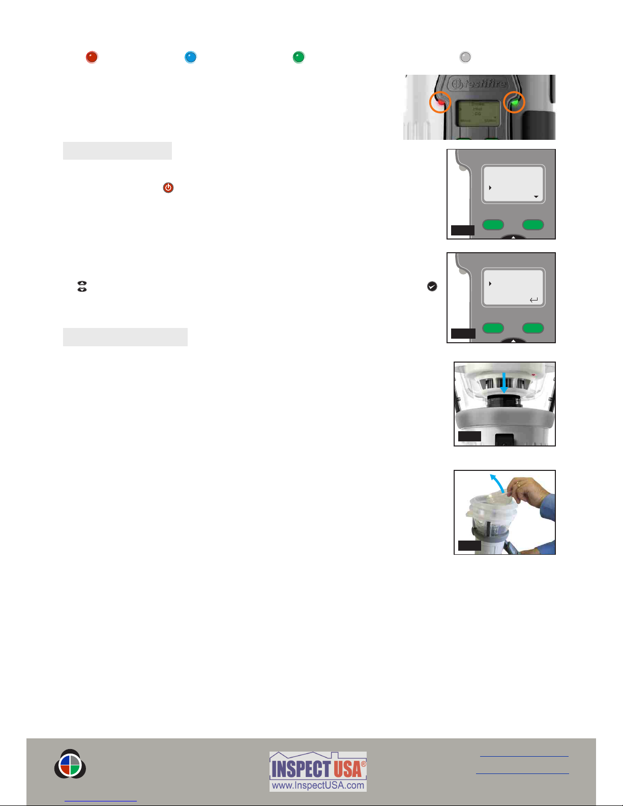
4.4 Turning the Unit On
To turn the unit on, press and hold the red ‘ON-OFF’ key for 2 seconds (Fig. 11).
The ‘Status’ LED will flash slowly green to indicate that the unit is in ‘STANDBY’ mode.
The first time the unit is powered-on (or after a ‘System Reset’ see Section 6.2), you
will be prompted to select the Testifire operating language for your region. Use the
‘UP’ and ‘DOWN’ keys to navigate and ‘ENTER’ key to select your required
operating language (Fig. 12).
This will display a confirmation screen (Fig. 13). Press the ‘MENU’
key to select or the ‘STATUS’ key to cancel. Once the language
has been selected the ‘MAIN’ menu will be displayed.
The chosen language can be changed at any time by pressing the
‘MENU’ key. Use the ‘UP’ and ‘DOWN’ keys to navigate the
menu and use the ‘ENTER’ key to select ‘Language’ (Fig. 14).
Pressing the ‘ESCAPE’ key goes back to the ‘STANDBY’ screen.
After long periods of non-use or when a Smoke Capsule has been
replaced, the unit will self-prime at power-on, prior to displaying
the ‘MAIN’ menu. Testifire will show the ‘Preparing for use Please
wait’ message for a short period while it is priming the circuits
ready for use (Fig. 15).
If the unit is left in Standby mode for more than 5 minutes, it will power off to conserve the battery.
Fig. 9
page 10
Spring Clips
Tip Protector
E
D
Fig. 10
F
F
E
M U L T I - S T I M U L U S D E T E C T O R T E S T E R
testifire®
E
E
www.testifire.com
Back to Contents Page
Fig. 11
Fig. 13
Fig. 12
English
Deutsch
Español
Français
Preparing for use
Please wait
Fig. 15
Fig. 14
English
Select Cancel
System Info.
Language
Sounder
System Reset
CO Capsule Removal Instructions (Testifire 2000 series only)
Only replace the CO capsule when it is empty. Testifire should be
turned off for five minutes to allow the ‘CO’ capsule to cool down
before removing it.
Release the lower access cover (Fig. 9) on the body of the Testifire D
unit by opening it from the right hand side.
Squeeze the spring clips (Fig. 9)on each side and gently pull the E
capsule out.
Do not touch the tip of the CO capsule as it may be hot.
CO Capsule Replacement Instructions
Remove the capsule from its outer carton and anti-static bag.
Remove the tip protector from the tip of the capsule (Fig. 10).F
Holding the capsule by the spring clips (Fig. 10) with the label E
uppermost, carefully insert the new capsule into the capsule
port. Push it into position, ensuring that the spring clips spring
out positively on both sides of the capsule and engage with the
port properly. Close the CO access cover (Fig. 9) securely.D

4.5 Using the Menus
Before turning Testifire on for the first time, it is recommended that you become familiar with system menus.
Testifire’s menu system is simple to navigate. Using the ‘UP’ and ‘DOWN’ menu navigation keys , you can
move the cursor through the ‘MAIN’ menu (Fig. 16). Press the ‘ENTER’ key to select stimuli from the
‘MAIN’ menu or to display sub menus.
Pressing the ‘ESCAPE’ key goes back to the ‘MAIN’ menu or, when a
test sequence has been programmed and the ‘MAIN’ menu is displayed,
the ‘ESCAPE’ key will cancel the programmed test sequence.
A ‘DOWN’ arrow on the bottom right of the ‘MAIN’ menu indicates
options are available below. Use the ‘DOWN’ key on the keypad to
move down through the menu. (Fig. 17).
The ‘UP’ arrow on the ‘MAIN’ menu indicates options available above.
Use the ‘UP’ key on the keypad to move up through the menu (Fig 18).
Press the ‘LEFT’ key on the keypad to go back one menu level.
: For a single test, use the ‘UP’ and ‘DOWN’ TIP
keys to highlight ‘Smoke’, ‘Heat’ or ‘CO’ as
required on the ‘MAIN’ menu. You do not need
to press the ‘ENTER’ key on the keypad to
select, just leave the required test stimuli
highlighted (Fig. 19).
page 11
Fig. 21
Fig. 20
Fig. 22
M U L T I - S T I M U L U S D E T E C T O R T E S T E R
testifire®
www.testifire.com
Back to Contents Page
4.6 Adjusting the Head Unit Angle
Correct head angle adjustment is important to make sure that the
detector to be tested is correctly positioned in the inner clear cup
and the user is in a safe and appropriate position to carry out the test.
The detector should touch the base of the Testifire inner clear cup
and should be level with the base of the detector (Fig. 20).
Adjust the head unit for the correct angle to access the detector to
be tested. Hold the body of Testifire and, pulling gently against the
spring, angle the head unit away from the Battery Baton (Fig. 21).
The head unit will be free to rotate to the desired position and, on
release, it will lock and remain locked for use (Fig. 22).
Keypad
Fig. 18Fig. 17
Smoke
Heat
CO
Menu Status
Fig. 19
Fig. 16
Smoke
Heat
CO
Menu Status
Heat
CO
Clear
Menu Status
Status KeyMenu Key
Escape KeyON/OFF Key
Enter Key
Menu
Navigation
Keys

Fig. 24
page 12
Fig. 23
M U L T I - S T I M U L U S D E T E C T O R T E S T E R
testifire®
www.testifire.com
Back to Contents Page
4.7 Testing High Profile Detectors
When testing high profile detectors, it may be necessary
to remove the inner clear cup to enable the detector to
sit in the correct position for a successful test. The inner
clear cup has a semi-circular cut-out on the side nearest
to the user interface. Place your finger in the cut-out and
carefully lift out the cup (Fig. 23). This will allow for
correct positioning of the high profile detector within
the cup (Fig. 24).
: To prevent Testifire going straight into a test mode, both the inner and outer clear cups should cleaned TIP
regularly with a damp non-abrasive cloth to remove any deposits or finger marks.

M U L T I - S T I M U L U S D E T E C T O R T E S T E R
testifire®
5. Using Your Testifire
WARNING
This product emits small amounts of carbon monoxide (CO) gas which is a harmful, odour-
less gas.
directly from the duct during a CO test or within 5 minutes of DO NOT INHALE
conducting a CO test.
Note: Under normal operating conditions, this emission will present no harm to the user.
For additional information please refer to the separate safety information provided.
CAUTION
This product contains hot surfaces and hot air is also emitted from the duct outlet.
the tip of the CO capsule when it has been removed if the unit has DO NOT TOUCH
been in operation within the previous 5 minutes. It will be very hot immediately after use
and may burn if touched.
insert fingers into the aperture from where the CO capsule has been removed. DO NOT
There are very hot surfaces which may burn if touched.
Avoid placing hands near the duct outlet during heat testing or within 5 minutes of
conducting heat testing. Hot air is emitted from the duct and the top of the duct will get
hot to the touch.
CAUTION
This product is intended to be used at height.
Exercise great care and always wear appropriate PPE (personal protective equipment) when
operating above head height in order to avoid the risk of injury.
. Keep proper footing and balance at all times. Proper footing and DO NOT OVER REACH
balance enables better control of the equipment in unexpected situations.
Care should always be taken when using Testifire at height. Pay particular attention to avoid
contact with overhead items such as light fittings, overhead power cables/busbars and any
other objects that could be accidentally dislodged which might cause danger to the operator
or anyone else in the vicinity.
After you have completed the preparation procedures, Testifire will be ready for use.
To carry out a simple, single stimulus test, use the ‘UP’ and ‘DOWN’ keys on
the keypad (as described in section 4.4 of this manual) to highlight the stimulus
required (Fig. 25). Although you can select the required stimulus by pressing the
‘ENTER’ key , all that is required for a single stimulus test is to highlight the
required stimulus (complex sequences of single-stimulus tests, or a simultaneous
multi-stimulus test are covered in Sections 5.8, 5.9 and 5.10). Fig. 25
Smoke
Heat
CO
Menu Status
page 13
www.testifire.com
Back to Contents Page
5.2 Testing a Detector
Raise Testifire up to the detector to be tested and place it centrally over the
detector. As the detector enters the clear cup and interrupts the built-in infrared
sensor in the head of Testifire, the selected tests or sequence of tests, begin.
NOTE: It is very important that the detector under test is in the correct position
within the clear cup for a successful test to take place. The detector should sit on the
platform and the top of the inner clear cup should be parallel to the detector base.
Ideally, the bellows should seal against the ceiling surface (Fig 28).
When testing high profile detectors, it may be necessary to remove the inner clear
cup to enable the detector to sit in the correct position for a successful test. The
inner clear cup has a semi-circular cut-out on the side nearest to the user interface.
Place your finger in the cut-out and carefully lift out the inner clear cup (Fig. 29).
: Ideally, the detector LED should be visible through the inner cup of the head TIP
unit. In some instances this is not possible. To improve visibility of the detector LED,
lower Testifire briefly, (2 seconds maximum), raising it again to continue the test.
For single-stimulus tests, the ‘Test Type’ LED will remain illuminated in one colour only, and for a sequence of
single-stimulus tests it will show the colour relating to the current test. For a multi-stimulus simultaneous test,
it will show all the colours relating to the stimuli in the test, alternating its colour repeatedly between them.
If after 2 minutes the test has not completed, Testifire will time out.
When the detector is activated, remove Testifire by lowering it gently. Testifire will return to ‘STANDBY’
mode as the Infrared beam is re-established and the ‘Status’ LED will flash slowly again.
Testifire may be used in a variety of modes for detector testing. Multiple stimuli (Smoke, Heat,
CO) may be tested either simultaneously (all at once) and/or sequentially (in various
combinations). The stimuli and their method of operation are described in the following sections.
5.1 Sounder Option
Two different ‘beeps’ are emitted from Testifire. A short ‘beep’ when pressing the
‘Power-On’ button and for a key press (‘Keypad’), and a longer 2-second ‘beep’
for errors (‘Warning’).
In some environments the sound may not be desirable. Testifire has an option that
allows both types of ‘beep’ to be disabled. Once disabled, the sound stays disabled
until it is manually enabled again or a ‘SYSTEM RESET’ takes place. (see Section 6.2).
To disable the sound, press the ‘MENU’ key and using the ‘UP’ and ‘DOWN’ keys
on the keypad, navigate to ‘Sounder’ (Fig. 26) and select using the ‘ENTER’ key .
Use the ‘ENTER’ key also to select ‘ON’ or ‘OFF’ for the ‘Keypad’ and ‘Warning’
sounds (Fig. 27).
Once the stimulus has been selected, the ‘Test Type’ LED will change colour to indicate the following:
Red = Heat Test Blue = Smoke Test Green = Carbon Monoxide Test Clear = Clearing
The ‘Status’ LED provides feedback on the modes of operation and alerts
you to errors or when a smoke or CO capsule is empty or incorrectly
fitted. The Indicating LED Reference Chart details all of the variations
(see Section 5.13).
page 14
Fig. 26
Sounder
Keypad Off
Warning Off
Fig. 27
M U L T I - S T I M U L U S D E T E C T O R T E S T E R
testifire®
Fig. 29
www.testifire.com
Back to Contents Page
System Info.
Language
Sounder
Service
Fig. 28
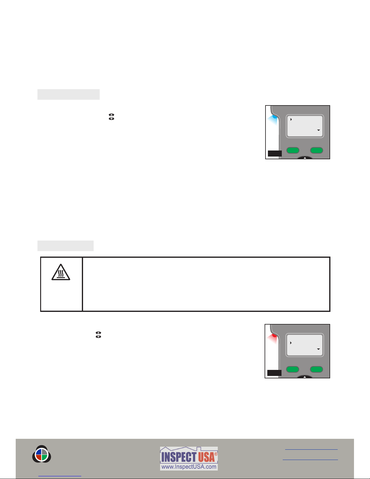
5.4 Heat Testing
To select a heat test on the ‘MAIN’ menu, move the cursor to ‘Heat’ using the ‘UP’
and ‘DOWN’ keys on the keypad (Fig. 31). The test will begin automatically when
the head unit is placed over the detector and the infrared beam is broken.
The ‘Test Type’ LED on Testifire will confirm that heat is being generated by
illuminating red.
Heat is blown from the duct immediately the test begins. The temperature of the
air emerging from the duct is such that it can heat the thermal sensor in the
detector.
The heat is produced in a narrow stream and is not intended to heat up the whole inner clear cup area of
Testifire. Instead, only the area immediately around the thermal sensor in the detector will be heated in order
to preserve battery power.
5.3 Smoke Testing
To select a smoke test on the ‘MAIN’ menu, move the cursor to ‘Smoke’ using the
‘UP’ and ‘DOWN’ keys on the keypad (Fig. 30). The test will begin automatically
when the head unit is placed over the detector and the infrared beam is broken.
The ‘Test Type’ LED on Testifire will confirm that smoke is being generated by
illuminating blue.
Smoke is generated and blown into the detector within a few seconds of the test
beginning.
Not all of the smoke is visible to the naked eye and it must not be assumed that there is a problem when
smoke is not immediately seen emerging from the unit.
The amount of smoke produced may vary throughout the test.
During a smoke test, a slight ‘popping’ noise may be heard during the smoke generation. This is normal and
part of the test procedure.
page 15
Smoke
Heat
CO
Menu Status
Fig. 30
CAUTION
Avoid placing hands near the duct outlet during heat testing or within 5 minutes of
conducting heat testing.
Hot air is emitted from the duct and the top of the duct will get hot to the touch.
Smoke
Heat
CO
Menu Status
Fig. 31
M U L T I - S T I M U L U S D E T E C T O R T E S T E R
testifire®
NOTE: Lowering Testifire during a test will do the following:
For less than 2 seconds: Nothing. The test will continue as soon as the detector re-enters the cup.
For more than 2 seconds: During a Sequential Test, Testifire will advance to the next test that is
programmed.
For more than 10 seconds: During a Sequential or Simultaneous Test, Testifire will reset and return to
the first test of the programmed test sequence.
www.testifire.com
Back to Contents Page

A ‘Hi Heat’ setting for fixed temperature detectors which operate at more than 90ºC (194ºF) is available. It is
recommended that for most tests the ‘Heat’ (normal heat) setting is used as this will conserve battery power.
To select a ‘Hi Heat’ test, use the ‘UP’ and ‘DOWN’
keys on the keypad to highlight ‘Heat’. Press the
‘STATUS’ key on the keypad (Fig 32), and then move
the cursor to ‘Hi Heat’ (Fig 33) using the ‘UP’ and
‘DOWN’ keys on the keypad. Press the ‘ENTER’
key to select ‘Hi-Heat’.
After selecting ‘Hi Heat’, Testifire will revert to the
‘Heat’ setting when the unit is switched off and on again.
Special Notes for Heat Detectors
Heat detectors have a thermal sensor (normally a thermistor) that detects heat. This is usually mounted
centrally within the detector which allows for easy alignment of Testifire. For heat detectors with either dual
or offset thermistors, the main duct of the Testifire head unit should be aligned with the thermal sensor.
Incorrect alignment could result in a failed test.
If after 2 minutes the test has not completed, Testifire will timeout. When Testifire is lowered (re-establishing
the Infrared beam) it will switch to ‘STANDBY’ mode, ready to carry out the next test. The ‘Status’ LED will
flash slowly alternating between green and red for 3 seconds before reverting to slowly flashing green indicating
‘STANDBY’ mode. For tests started with the Infrared Remote Control, Testifire's timeout mode is different. The
red-green flashing led timeout mode will only last for 10 seconds after which the test sequence will be cancelled
and the unit will revert back to standby mode.
When using the ‘Heat’ setting, care should also be taken not to leave the Testifire head unit in position over a
detector for too long. The plastics used in some detectors with thermal sensing elements that respond to rate-
of-rise, or reasonably low absolute temperatures, may soften if exposed to heat for long periods of time.
Extra care should be taken not to overheat a detector when using the ‘Heat’ setting combined with ‘Smoke’
and/or ‘CO’ (two or more at the same time) as there may be a delay in response from the slowest sensor.
This may mean that the heat has been applied for longer than necessary for the element of the detector to
activate.
page 16
NFPA 72 - Heat Detector Testing
To enable compliance with NFPA 72, a 60 second heat timer option is available. Selecting this option stops the
heat test at 60 seconds as required by the standard. A ‘Timer’ option is available for ‘Heat’ and ‘Hi-Heat’
settings.
To select the ‘Timer’ option, highlight ‘Heat’ or ‘Hi Heat’ on the ‘MAIN’ menu. Press the ‘STATUS’ key (Fig. 34),
and move the cursor by using the ‘UP’ and ‘DOWN’ keys on the keypad to highlight ‘Timer’ on the menu
(Fig. 35). Press the ‘ENTER’ key on the keypad to select. A countdown icon will appear on the ‘MAIN’ menu
alongside ‘Heat’ or ‘Hi Heat’ (Fig. 36).
Once the Timer option has been selected it will stay on until it is turned off manually or a ‘SYSTEM RESET’
takes place (see Section 6.2).
Fig. 36
Smoke
Hi Heat
CO
Menu Status
Fig. 35
Heat Status
Hi Heat On
Timer Off
Fig. 34
Fig. 32 Fig. 33
Heat Status
Hi Heat On
Timer On
M U L T I - S T I M U L U S D E T E C T O R T E S T E R
testifire®
www.testifire.com
Back to Contents Page

page 17
5.5 Carbon Monoxide (CO) Testing
To select a CO test on the ‘MAIN’ menu, move the cursor to ‘CO’ using the ‘UP’ and ‘DOWN’ keys on the
keypad (Fig. 37). The test will begin automatically when the head unit is placed over the detector and the
infrared beam is broken.
CO is invisible and it will not be apparent that the gas is present during a test. The
‘Test Type’ LED on Testifire will confirm that CO is being generated by illuminating
green.
CO is generated and gently blown into the detector.
When used as directed, Testifire is safe for testing CO Fire Detectors. It is not
suitable for testing most Life Safety CO Detectors which typically require exposure
to far higher level of carbon monoxide to activate.
After carrying out a CO test (singularly or as part of a programme). Testifire cools the CO heater element. The
right hand ‘Status’ LED will flash Green and Red with longer gaps between the flashes. Once the CO heater
element temperature has been reduced, the ‘Status’ LED will indicate ‘STANDBY’ mode, by flashing Green
slowly. The next CO test can then be carried out.
5.6 Clearing the Detector
This operation blows air into the detector to clear it of smoke. It does not clean the
internal components of the detector.
To select the clearing function on the main menu, move the cursor to ‘Clear’ using
( )
the ‘UP’ and ‘DOWN’ keys on the keypad Fig. 38 . The clearing operation will
begin automatically when the head unit is placed over the detector and the infrared
beam is broken. The ‘Status’ LED will flash fast in green or fast in red if the battery
is low.
The ‘Test Type’ LED will not be illuminated at all during a clearing operation.
: Set ‘Clear’ as part of a sequential test with ‘Smoke e.g. ‘Smoke’ is 1 and ‘Clear’ TIP
is set to 2 (Fig. 39). This will speed up the testing of smoke detectors as the
clearing process will remove the possibility of the detector reactivating. See Section
5.9 for details of how to set up a sequential test.
WARNING
This product emits small amounts of carbon monoxide (CO) gas which is a harmful,
odourless gas.
directly from the duct during a CO test or within 5 minutes of DO NOT INHALE
conducting a CO test.
Note: Under normal operating conditions, this emission will present no harm to the user.
For additional information please refer to the separate safety information provided.
Smoke
Heat
CO
Menu Status
Fig. 37
Fig. 38
Smoke
Heat
CO
Menu Status
Smoke
Heat
Clear
Menu Status
M U L T I - S T I M U L U S D E T E C T O R T E S T E R
testifire®
www.testifire.com
Back to Contents Page
Fig. 39
Smoke 1
Heat
Clear 2
Menu Status
This manual suits for next models
7
Table of contents
Other Detectortesters Test Equipment manuals


Popular Test Equipment manuals by other brands

Fluke
Fluke NetTool Quick reference guide

Platinum Tools
Platinum Tools Fault Trapper TFT100 quick start guide

Proceq
Proceq ZCC 2087 Series instruction manual

Chauvin Arnoux
Chauvin Arnoux C.A 6115N user manual

BRUEL & KJAER
BRUEL & KJAER 4825 Technical documentation

Atlas
Atlas Xenotest Beta+FD operating manual


