FineTek JTR Technical manual

1
JTR Guided Wave
Radar Level Sensor
Operation Instruction
FineTek Co.,Ltd.
No.16, Tzuchiang St., Tucheng Industrial Park, New Taipei City 23678
Tel:886-2-22696789 Fax:886-2-22686682
Website:http://www.fine-tek.com E-mail:[email protected]
08-JTR3-B6-EK,07/17/2020

2
TABLE OF CONTENTS
1.Introduction………………………………………………………………………………..4
2.Product warranty………………………………………………………………………….5
2.1 New product warranty.............................................................................................5
2.2 Repair Warranty......................................................................................................6
2.3 International Service Office.....................................................................................6
3. Product Inspection………………………………………………………………………..7
3.1 Configuration..........................................................................................................7
3.1.1 Model Label.........................................................................................................7
3.1.2 Product contents..................................................................................................7
3.2 Safety Check ..........................................................................................................7
4. Product Introduction……………………………………………………………………..8
4.1 Product Principles...................................................................................................8
4.2 Advanced Functions ...............................................................................................8
4.2.1 Bottom signal enhancement & tracking technology.............................................8
4.2.2 Dual-Level interface measurement......................................................................9
5. Features……………………………………………………………………………………10
6. Specification……………………………………………………………………………...11
7. Installation…………………………………………………………………….…………..15
7.1 General Instructions.............................................................................................. 15
7.1.1 Lock instrument ................................................................................................. 15
7.1.2 Moisture proof instructions.................................................................................15
7.1.3 Operating conditions.......................................................................................... 15
7.2 Installation Instruction...........................................................................................16
7.2.1 Installation site...................................................................................................16
7.2.2 Feeding tank installation precautions................................................................. 18
7.2.3 Blind area ..........................................................................................................18
8 Wiring Instruction………………………………………………………………………..19
8.1 Preparations .........................................................................................................19
8.1.1 Please note the following safety precautions before use:..................................19
8.1.2 Connecting cable...............................................................................................19
8.1.3 Power supply..................................................................................................... 19
8.2 Wiring Instructions:............................................................................................... 20
8.2.1 Connection methods.......................................................................................... 20
8.2.2 Wiring steps.......................................................................................................20
8.3 Startup Instructions...............................................................................................22
9. Display Module Adjustment and Setting……………………………………………23
9.1 Operation Steps.................................................................................................... 23

3
9.1.1 Adjustment.........................................................................................................24
9.2 Menus...................................................................................................................24
9.2.1 Measurement Settings Menu............................................................................. 25
9.2.2 Display settings Menu........................................................................................27
9.2.3 Diagnostics........................................................................................................29
9.2.4 Additional Settings Menu ...................................................................................30
9.2.5 Product Information Menu ................................................................................. 31
9.3 Parameter table list...............................................................................................32
9.4 Bottom Tracking Probe Set up..............................................................................34
10. Warnings and Cautions………………………………………………………………..36
11. Troubleshooting………………………………………………………………………...37
12. Communication Protocol Table………………………………………………………38
4
1. Introduction
Thank you for purchasing FineTek products. This operation manual will describe(s) the product's
characteristics, working principle, operation, maintenance and troubleshooting, helping users
familiarize with the product and avoid mishap from incorrect usage.
Before using the product, please read this operation manual carefully.
If you require further clarifications or details, please contact our company.
Product updates will be uploaded onto our company website at www.fine-tek.com; users may
download the information from there.
Please do not disassemble or repair the product yourself; otherwise the warranty will become
invalid. Do send the item back to our company instead, or contact our customer hot-line for
help.
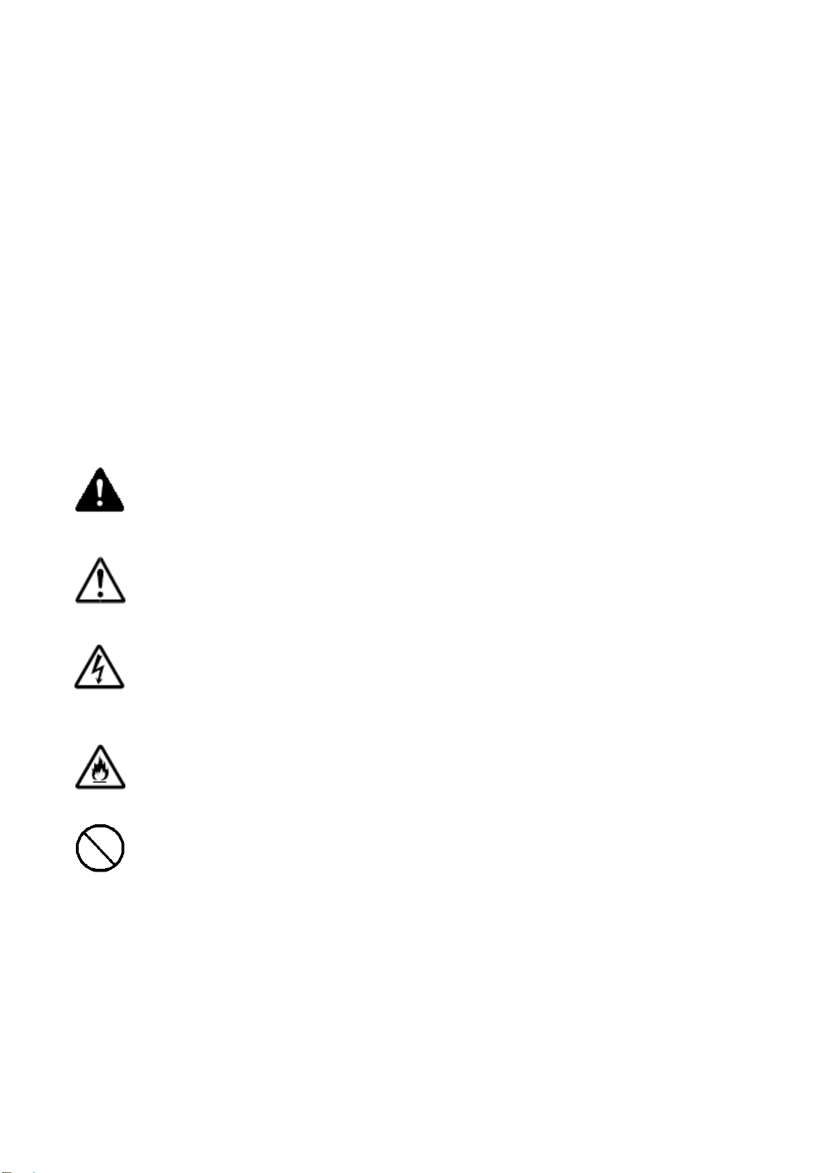
Warning Symbol:
Danger→indicates possibility of major or fatal disaster if operation is goes wrong.
Attention→indicates possibility of a certain degree of injury & equipment damage if the
operation goes wrong.
Electric Shock →indicates possibility of receiving an electric shock.
Fire →a warning that fire may occur
Prohibited →Forbidden operation.

5
2. Product warranty
2.1 New product warranty
FineTek products are guaranteed a warranty period of 12 months starting from the date of
delivery whereby the cost of testing, replacement parts, repairs and other expenses are
waived.
If product is damaged during delivery, you may request for a replacement within 7 days.
If product needs to be sent back to FineTek for repairs, please avoid disassembling it
yourself. In addition, product needs to be packed properly to avoid damage during shipping.
Product warranty is only applicable to items that are used and installed accordingly. It does
not cover items that are used extraordinarily or outside its scope of operations.
The following conditions will result in product not be covered by warranty; testing,
replacement parts & repair costs will be charged.
The warranty period for part or whole product has expired.
Product damage due to failure in using the operation manual properly or poor operating
environment.
Product damage due to force majeure (e.g. natural disasters), carelessness (e.g. scratch, fall,
heavy blow), negligence (e.g. use of inappropriate voltage, corrosion, improper storage) or
other abnormal factors.
Customer or user had installed, modified or repaired the product not authorized or approved
by FineTek.
Table of contents
Other FineTek Accessories manuals


