STRONG POINTS
→EASY TO INSTALL : 1/4 TURN, THE
INDICATOR IS MARKED ‘IND’
→CONNECTION : STAINLESS STEEL
Installation and operation manual
01-DETCO-NT011 rev A1
CAP 212
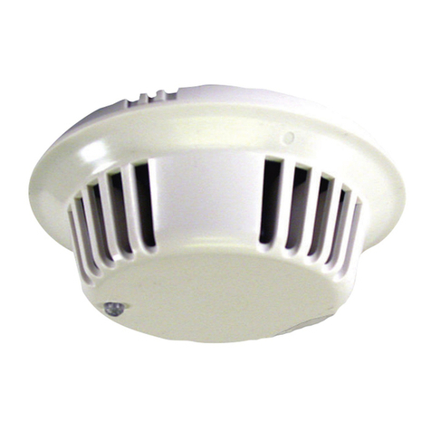
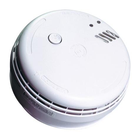
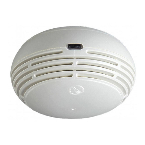
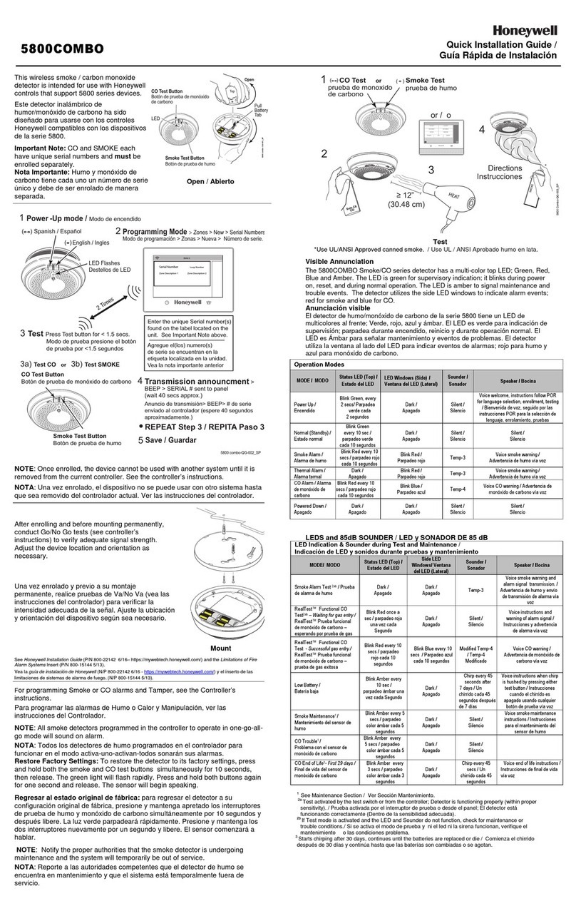
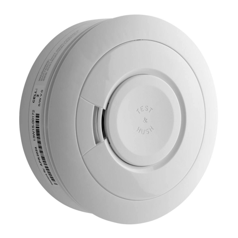
Heat detector CAP 212
→Presentation
How the heat detector works ?
The heat detection is carried out by a thermal probe which permanently
measures the room temperature. The detector analyses the temperature
in 2 simultaneous ways :
→Comparison of the room temperature at a pre-determined thres-
hold and if this threshold is overtake, the detector moves to the
alarm mode, whatever the temperature rise’s speed. This is the
thermostatic mode.
→Computation of the temperature rise’s speed and when the tem-
perature rises according to a predetermined speed, the detector
moves to the alarm mode. This is the rate-of-rise (ROR) mode.
The temperature probe is composed of a negative temperature coef-
ficient (NTC) thermistor at low thermal inertia.
→installation
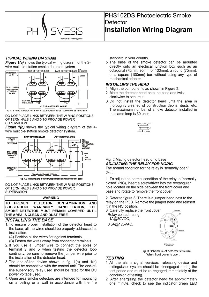
Mount the base of the detector by fixing it firmly. Connect according
the enclosed wiring diagram, respecting the polarities.
In case you lay a coating such as paint near to the detector, make sure
to protect it against any possible pollution.
Put the control panel into service and proceed to the recommended
tests in the panel user manual. In particular, operate a detection test
with an adequate device (such as a heat detector tester).
→oPeration
In case of detection, the red indicator of the detector turns on and a
signal is sent to the control panel by mean of an overconsumption of
current. The red indicator is on until the reset of the panel.
Proceed to periodical tests on the detector (at least twice a year). These
operations must be performed by a qualified company.
Terminal Name Connection
1 -IA - remote indicator
2 + S + line output
3 + E + line input
4 0 V
5 Not used
→technical characteristics
Material : moulded white ABS
Wiring base : reference S100 (item number ACCDE001)
Remote indicator output : maximum 10 mA at 12 V
Compliant EN 54-5 : E2 087 D0
Supply voltage + 8,5 V to + 30 V continuous
Quiescent current below 120 µA at 12 V
Alarm current 25 mA ± 2 mA at 12 V
Remote indicator voltage (limited at 10 mA) 15 to 30 V continuous voltage
Thermal characteristics
Rating (according to EN 54-5 : 2000) A1R
Typical implementation temperature 25°C
Maximum implementation temperature 50°C
Static temperature response 60°C
Stabilization time (until the detector is operational in ROR
mode)
3 min 20 s for the temperature rise’s speed equal or superior to 10°C per min.
40 min for the temperature rise’s speed inferior to 10°C per min.
